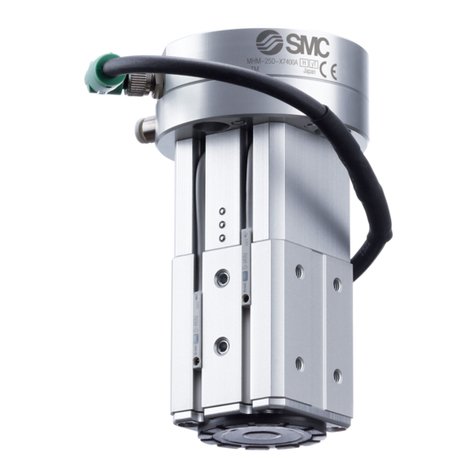
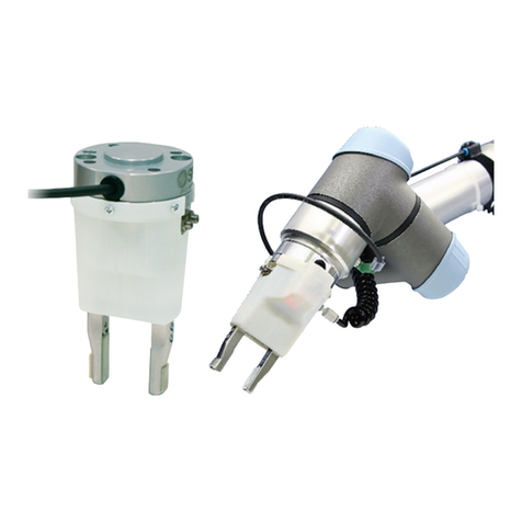
SMC Networks MHM-25D-X7400A User manual

Doc.No.MH*-OMY0015
PRODUCT NAME
Magnet Gripper Unit for Collaborative Robots
MODEL / Series / Product Number
MHM-25D-X7400A

- 1 -
Contents
Safety Instructions........................................................................................................- 2 -
1.List of included items ................................................................................................- 4 -
2.Parts description of the magnet gripper..................................................................- 5 -
3.Product Specifications ..............................................................................................- 6 -
3-1. Specifications.....................................................................................................- 6 -
3-2. Gripping force.....................................................................................................- 7 -
3-3. Dimensions.........................................................................................................- 9 -
3-4. Connector and pin layout................................................................................- 10 -
3-5. Center of gravity...............................................................................................- 11 -
4.Product Specifications ............................................................................................- 12 -
4-1. Magnet gripper .................................................................................................- 12 -
4-2. 3-port solenoid valve .......................................................................................- 13 -
4-3. Auto switch.......................................................................................................- 14 -
5.Operating method or operation ..............................................................................- 15 -
5-1.Precautions for Design....................................................................................- 15 -
5-2. Installation ........................................................................................................- 16 -
5-3. U R C a p ...........................................................................................................- 19 -
5-4. Air supply..........................................................................................................- 25 -
5-5. Piping ................................................................................................................- 25 -
5-6. Operating environment....................................................................................- 25 -
5-7. Lubrication........................................................................................................- 26 -
6.Maintenance .............................................................................................................- 26 -

- 2 -
Safety Instructions
These safety instructions are intended to prevent hazardous situations and/or equipment damage.
These instructions indicate the level of potential hazard with the labels of “Caution,” “Warning” or “Danger.”
They are all important notes for safety and must be followed in addition to International Standards
(ISO/IEC)*1) , and other safety regulations.
*1) ISO 4414: Pneumatic fluid power -- General rules relating to systems.
ISO 4413: Hydraulic fluid power -- General rules relating to systems.
IEC 60204-1: Safety of machinery -- Electrical equipment of machines.(Part 1: General requirements)
ISO 10218: Manipulating industrial robots -Safety.
etc.
Caution
Caution indicates a hazard with a low level of risk which, if not avoided, could result
in minor or moderate injury.
Warning
Warning indicates a hazard with a medium level of risk which, if not avoided, could
result in death or serious injury.
Danger
Danger indicates a hazard with a high level of risk which, if not avoided, will result
in death or serious injury.
Warning
1. The compatibility of the product is the responsibility of the person who designs the equipment or
decides its specifications.
Since the product specified here is used under various operating conditions, its compatibility with specific
equipment must be decided by the person who designs the equipment or decides its specifications based on
necessary analysis and test results.
The expected performance and safety assurance of the equipment will be the responsibility of the person who
has determined its compatibility with the product.
This person should also continuously review all specifications of the product referring to its latest catalog
information, with a view to giving due consideration to any possibility of equipment failure when configuring the
equipment.
2. Only personnel with appropriate training should operate machinery and equipment.
The product specified here may become unsafe if handled incorrectly.
The assembly, operation and maintenance of machines or equipment including our products must be
performed by an operator who is appropriately trained and experienced.
3. Do not service or attempt to remove product and machinery/equipment until safety is confirmed.
1.The inspection and maintenance of machinery/equipment should only be performed after measures to
prevent falling or runaway of the driven objects have been confirmed.
2.When the product is to be removed, confirm that the safety measures as mentioned above are implemented
and the power from any appropriate source is cut, and read and understand the specific product precautions
of all relevant products carefully.
3. Before machinery/equipment is restarted, take measures to prevent unexpected operation and malfunction.
4. Contact SMC beforehand and take special consideration of safety measures if the product is to
be used in any of the following conditions.
1. Conditions and environments outside of the given specifications, or use outdoors or in a place exposed to
direct sunlight.
2. Installation on equipment in conjunction with atomic energy, railways, air navigation, space, shipping,
vehicles, military, medical treatment, combustion and recreation, or equipment in contact with food and
beverages, emergency stop circuits, clutch and brake circuits in press applications, safety equipment or
other applications unsuitable for the standard specifications described in the product catalog.
3. An application which could have negative effects on people, property, or animals requiring special safety
analysis.
4.Use in an interlock circuit, which requires the provision of double interlock for possible failure by using a
mechanical protective function, and periodical checks to confirm proper operation.
- 3 -
Safety Instructions
Caution
The product is provided for use in manufacturing industries.
The product herein described is basically provided for peaceful use in manufacturing industries.
If considering using the product in other industries, consult SMC beforehand and exchange
specifications or a contract if necessary.
If anything is unclear, contact your nearest sales branch.
Limited warranty and Disclaimer/Compliance Requirements
The product used is subject to the following “Limited warranty and Disclaimer” and “Compliance
Requirements”.
Read and accept them before using the product.
Limited warranty and Disclaimer
1.The warranty period of the product is 1 year in service or 1.5 years after the product is
delivered,whichever is first. 2)
Also, the product may have specified durability, running distance or replacement parts. Please
consult your nearest sales branch.
2. For any failure or damage reported within the warranty period which is clearly our responsibility,
a replacement product or necessary parts will be provided.
This limited warranty applies only to our product independently, and not to any other damage
incurred due to the failure of the product.
3. Prior to using SMC products, please read and understand the warranty terms and disclaimers
noted in the specified catalog for the particular products.
2) Vacuum pads are excluded from this 1 year warranty.
A vacuum pad is a consumable part, so it is warranted for a year after it is delivered.
Also, even within the warranty period, the wear of a product due to the use of the vacuum
pad or failure due to the deterioration of rubber material are not covered by the limited
warranty.
Compliance Requirements
1. The use of SMC products with production equipment for the manufacture of weapons of mass
destruction(WMD) or any other weapon is strictly prohibited.
2. The export of SMC products or technology from one country to another is governed by the
relevant security laws and regulations of the countries involved in the transaction. Prior to the
shipment of an SMC product to another country, ensure that all local rules governing that export
are known and followed.
Caution
SMC products are not intended for use as instruments for legal metrology.
Measurement instruments that SMC manufactures or sells have not been qualified by type approval
tests relevant to the metrology (measurement) laws of each country.
Therefore, SMC products cannot be used for business or certification ordained by the metrology
(measurement) laws of each country.
! Caution
SMC products are not intended for use as instruments for legal metrology.
Measurement instruments that SMC manufactures or sells have not been qualified by type approval
tests relevant to the metrology (measurement) laws of each country.
Therefore, SMC products cannot be used for business or certification ordained by the metrology
(measurement) laws of each country.

- 4 -
1.List of included items
Magnet gripper unit 1pc.
M8 8 Pin connector 1pc.
Positioning pin (6×10) 1pc.
For positioning the product.
Hexagon socket head cap screw
(M6×23) 4pcs.
For mounting the product.
Coil tube for piping (TU0425) 2m

- 5 -
2.Parts description of the magnet gripper
Auto switch:D-M9P
Magnet gripper
One-touch fitting:
KQ2S04-M5N
Metering Valve with
Silencers:
ASN2-M5-X937
3-port solenoid valves:
V114-5LU
ISO9409-1
compliant flange
M8 8 pin connector cable
Positioning pins:3x6
Hexagon socket head
cap screws:M4x12
Hexagon socket head cap
screws:M4x16
Adapter
Hexagon socket head
cap screw:M4x35

- 6 -
3.Product Specifications
3-1. Specifications
Specifications
Model No.
MHM-25D-X7400A
Fluid
Air
Operating method
Double acting
Operating pressure (MPa)
0.2 to 0.6MPa
Proof pressure
0.9MPa
Ambient and operating fluid temperature(oC)
-10 to 50
Gripping
Force *
Workpiece
thickness:2mm
160N
Workpiece
thickness:6mm
200N
Residual holding force
0.3 N or less
Lubrication
Non-lube
Weight (g)
590g
Auto switch model
D-M9P
Standard for mounting onto the robot
ISO9409-1-50-4-M6
Connector configuration of the accessory
Both side M8 8 pin connector(Socket)
*1 Theoretical holding force (reference value) when a low carbon steel plate is held by entire surface
attraction surface
In the default setting, the auto switch is fixed at the workpiece release position.
* For examples of setting auto switch and setting of mounting position of auto switches, please refer to
the MHM Series catalogue P.12 onwards on our website (www.smcworld.com).
* Auto switches are used for checking the operation of the magnet gripper. They do not guarantee the
actual holding and release of the workpiece. For checking the holding / release of the workpiece, a
proximity sensor should be mounted separately.
Detect the magnet position
For workpiece holding.
Detect the magnet position
for workpiece release.
Detection location at
workpiece is holding position
Detection location at
workpiece release position

- 7 -
3-2. Gripping force
Holding conditions.
To lift workpieces vertically, be sure to take into consideration the acceleration rate, air pressure,
impact etc., in addition to the mass of the workpieces.
Consider the center of gravity of the workpiece to avoid moments being applied the magnet gripper
as much as possible.
If multiple magnet grippers are used for transferring a workpiece with a large surface area, properly
allocate the magnet grippers to maintain balance.
Horizontal movement of the magnet gripper may cause sideslip of the workpiece depending on the
acceleration or friction coefficient between the pad and workpiece. Therefore, the acceleration rate
of the lateral movement must be minimized.
Use the magnet gripper for horizontal handling. Adequate safety factor needs to be considered for
inclined handling or vertical handling.。
Thin workpieces may be deformed during transportation. It is recommended to use multiple magnet
grippers for scenarios such as this.
Lifting direction
Moving direction
Horizontal handling
Basic orientation
Inclined handling
Vertical handling

- 8 -
Calculate the required holding force.
The holding force graph shows the theoretical value for low carbon steel plate. Holding forces very
depending on the material and shape of the workpiece. Please perform a holding test referring to the
value selected based on the graph.

- 9 -
3-3. Dimensions
Refer to P12, P13 and P14 for the dimensions of the magnet gripper, valves and auto switches.

- 10 -
3-4. Connector and pin layout
PIN No.
Color
Function
Explanation
1
White
-
-
2
Brown
-
-
3
Green
Auto switch
(For holding position)
-
4
Yellow
Auto switch
(For releasing position)
-
5
Gray
+24V
Power supply for
24 VDC
6
Pink
Valve ON/OFF
(For holding position)
-
7
Blue
Valve ON/OFF
(For releasing position)
-
8
Red
GND
Power supply for
0 VDC
M8 8 Pin connector(Plug)

- 11 -
3-5. Center of gravity
Center of gravity
X
Y
Z
-0.1
-0.5
55.8
Flange
mounting surface
X
Z
Y
Z
Y
X

- 12 -
4.Product Specifications
* For detailed specifications not included in this document, please refer to the our website
(www.smcworld.com) or operation manual.
4-1. Magnet gripper
Specifications
Fluid
Air
Operating pressure [MPa]
0.2 to 0.6
Operating method
Double acting
Proof pressure
0.9MPa
Ambient and operating fluid
temperature(oC)
-10 to 60
Gripping
force *
Workpiece
thickness:2mm
160N
Workpiece
thickness:6mm
200N
Residual holding force
0.3 N or less
Lubrication
Non-lube
Weight (g)
244
*1 Theoretical holding force (reference value) when a low carbon steel plate is held by entire surface
attraction surface
Dimensions.

- 13 -
4-2. 3-port solenoid valve
Specifications
Solenoid specifications
Model No.
V114-5LU
Fluid
Air
Ambient and operating fluid temperature(oC)
-10 to 50 (No freezing)
Response time [ms]
ON:5 or less OFF:4 or less
Minimum operation frequency [Hz]
20
Lubrication
Non-lube
Mounting orientation
Free
Impact resistance/Vibration resistance (m/s2)
150/30
Enclosure rating
Dustproof
Model No.
V114-5LU
Electrical entry
L shaped plug connector (L)
Coil rated voltage [V]
24
Allowable voltage fluctuation
-10 to 10%
Power consumption [W]
0.4
[Starting 0.4,Holding 0.1]
Surge voltage suppressor
Please refer to page 1367 of the
Best Pneumatics catalogue.
Indicator LED
LED

- 14 -
4-3. Auto switch
Auto Switch Specifications
D-M9P(With indicator light)
Auto switch model
D-M9P
Electrical entry direction
In-line
Wiring
3-wire
Output
PNP type
Applicable load
IC circuit,Relay,PLC
Power supply voltage
DC5・12・24V(4.5 to 28V)
Current consumption
10 mA or less
Load voltage
-
Load current
40 mA or less
Internal voltage drop
0.8 V or less at 10 mA (2 V or less at 40 mA)
Current leakage
100 μA or less at 24 VDC
Indicator LED
Red LED illuminates when turned ON.
Standard
CE marking、RoHS
Dimensions
D-M9P

- 15 -
5.Operating method or operation
5-1.Precautions for Design
Warning
1.The product is designed for use only in compressed air systems. Do not operate at pressures or
temperatures, etc., beyond the range of the specifications, as this can cause damage or malfunction
of the cylinder and other equipment. (Refer to the specifications.)
Please contact SMC if using fluids other than compressed air. The product cannot be guaranteed if
is used outside of the specification range.
2.Take safety measures (e.g. mounting protective covers) when there is a danger of fingers being
caught in a gripper or workpieces causing damage, etc.
3.There is a danger of workpieces dropping if there is a decrease in gripping force due to a drop in
circuit pressure caused by a power failure, etc. It is necessary to take measures such as drop
prevention so that injury and damage to machinery or equipment can be prevented.
4. If the product is used for a purpose other than the transportation of a workpiece such as positioning
or clamping, please consult SMC.
!Caution
1. Finite orbit type guide is used in the actuator finger part. By using this, when there are inertial force
which cause by movements or rotation to the actuator, steel ball will move to one side and this will
cause a large resistance degrade the accuracy. When there are inertial force which cause by
movements or rotation to the actuator, operate the finger to full stroke.

- 16 -
5-2. Installation
!Warning
1. Install and operate the product only after reading the Operation Manual carefully and
understanding its contents. Also, keep the manual where it can be referred to as necessary.
2. When installing the products, allow access for maintenance.
3. Do not scratch or dent the air gripper by dropping or bumping it when mounting.
Slight deformation can cause inaccuracies or a malfunction.
4. Tighten the screw within the specified torque range when mounting the attachment.
Tightening with a torque above the limit can cause malfunction, while insufficient tightening can
cause slippage and dropping.
How to mount attachment to the finger
Make sure to mount the attachments on fingers with the tightening torque in the table below by
using bolts, etc., for the female threads on fingers.
!Caution
1. Install and operate the product only after reading the Operation Manual carefully and
understanding its contents. Also, keep the manual where it can be referred to as necessary.
2. Allow sufficient space for maintenance and inspection.
3.When the magnet moves toward the magnetic attraction surface, holding force is generatedonthe
attraction surface, Make sure that holding force is not generated when working around the
magnet gripper so the your fingers do not get caught in the magnet gripper.
Warning
1. Do not scratch or dent the magnet gripper by dropping or bumping it when mounting.
Even a slight deformation can cause malfunction.
2. Be careful with the magnetic attraction of parts of objects around the magnet gripper when
mounting the magnet gripper while it is in its holding position (the piston is on the attraction side).
They may cause injury.
3. When mounting the product, tighten it with screws of appropriate length at an appropriate torque.
Tightening with a torque greater than the specified torque can cause malfunction, while規insufficient
tightening can cause slippage and dropping.
4. Do not apply impact load to the center of the magnetic attraction surface.
Otherwise, it may result in a breakage or malfunction.
Center of the attraction surface

- 17 -
How to Mount Magnet Gripper
Adjust the robot arm position before mounting so that the mounting is easy.
(1)Mounting to the robot arm
(2)Connecting the M8 connector
* Do not energize while securing the connector.
* Check that the connector is not loose.
Robot arm end
Hexagon socket head
cap screw (M6 x 23)
Max. tightening torque:
6.3Nm
Positioning
pin

- 18 -
Operation time adjustment method for holding / releasing the workpiece
The piston operation time during workpiece holding / release can be adjusted by adjusting the opening of the
metering speed controller valve.
* (1) Workpiece holding time: Time required when the piston and magnet travel from the workpiece
release position to the workpiece holding position
* (2) Workpiece release time: Time required when the piston and magnet travel from the workpiece
holding position to the workpiece release position
* Use a flat blade screwdriver for adjusting the restriction of the metering valves.
* Keep the restriction of the 2 metering valves approximately the same. If they are different too much,
the operation may become unstable.
Magnet gripper workpiece holding / release time
Metering valve
For adjusting the time to move to the
workpiece holding position.
Metering valve
For adjusting the time to move to the
workpiecepiece release position.
②
Magnet
Piston
①
Workpiece
release position
Workpiece
holding position
Magnified view of the metering valve
Adjustment groove
(for flat blade screwdriver)

- 19 -
5-3. U R C a p
Installation and basic setting
1. Installation of URCap
(1) Tap the "URCap" menu from the robot settings screen.
(2) Insert the USB memory with a cop of the downloaded file into the teaching pad and tap the "+"
button.
(3) Select "SMC-Air Gripper Unit-xxx.urcap" from the file screen and tap the "open" button.
(4) Tap the "Restart" button to restart the robot.
①
②
Table of contents
Other SMC Networks Robotics manuals

SMC Networks
SMC Networks FAS-200 User manual

SMC Networks
SMC Networks MHM-25D-X7400A-CRX User manual

SMC Networks
SMC Networks JMHZ2-16D-X7400B User manual

SMC Networks
SMC Networks MHM-25D-X7400A-TM User manual

SMC Networks
SMC Networks JMHZ2-16D-X7400B-HC10-N User manual

SMC Networks
SMC Networks JMHZ2-16D-X7400B-DTB-N User manual

SMC Networks
SMC Networks ZXP7 01-X1 Series User manual

SMC Networks
SMC Networks JMHZ2-16D-X7400B-TM User manual

SMC Networks
SMC Networks JMHZ2-16D-X7400B-ASSISTA User manual

SMC Networks
SMC Networks MHM-25D-X7400A-DTP-N User manual