manuals.online logo
Brands
  1. Home
  2. •
  3. Brands
  4. •
  5. SMC Networks
  6. •
  7. Robotics
  8. •
  9. SMC Networks JMHZ2-20D-X7510 User manual

SMC Networks JMHZ2-20D-X7510 User manual

JMHZ-TF2Z397EN
Page 1 of 2
Instruction Manual
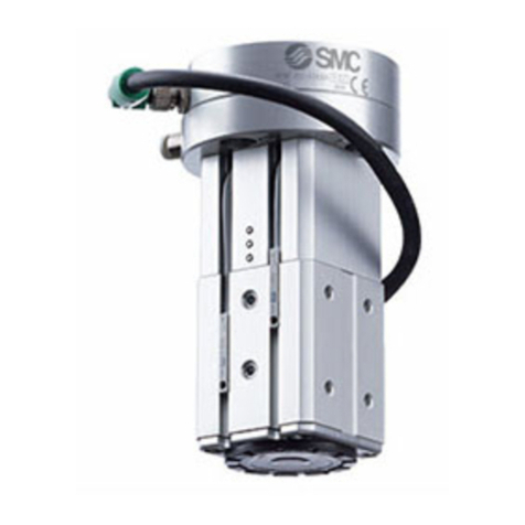
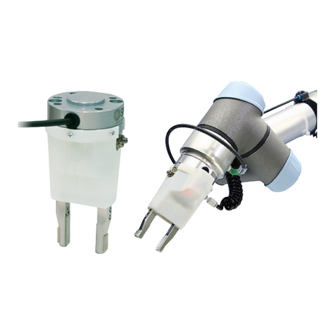
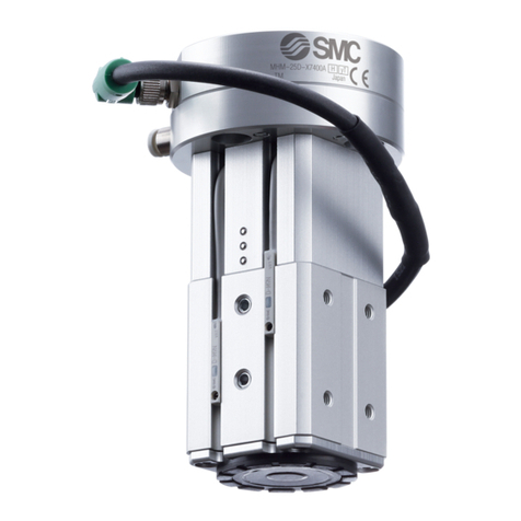
Air Gripper for Collaborative Robots
JMHZ2-20D-X7510
The intended use of this parallel type air gripper is to convert the potential
energy provided by compressed air into a force which causes mechanical
linear motion of the fingers.
1 Safety Instructions
These safety instructions are intended to prevent hazardous situations
and/or equipment damage. These instructions indicate the level of
potential hazard with the labels of “Caution,” “Warning” or “Danger.”
They are all important notes for safety and must be followed in addition
to International Standards (ISO/IEC)*1), and other safety regulations.
*1) ISO 4414: Pneumatic fluid power - General rules relating to systems.
ISO 4413: Hydraulic fluid power - General rules relating to systems.
IEC 60204-1: Safety of machinery - Electrical equipment of machines.
(Part 1: General requirements)
ISO 10218-1: Robots and robotic devices - Safety requirements for
industrial robots - Part 1: Robots.
Refer to product catalogue, Operation Manual and Handling
Precautions for SMC Products for additional information.
Keep this manual in a safe place for future reference.
Caution
Caution indicates a hazard with a low level of risk which, if
not avoided, could result in minor or moderate injury.
Warning
Warning indicates a hazard with a medium level of risk
which, if not avoided, could result in death or serious injury.
Danger
Danger indicates a hazard with a high level of risk which, if
not avoided, will result in death or serious injury.
Warning
Always ensure compliance with relevant safety laws and
standards.
All work must be carried out in a safe manner by a qualified person in
compliance with applicable national regulations.
2 Specifications
2.1 Product Specifications
Model
JMHZ2-20D-X7510
Bore Size [mm]
20
Fluid
Air
Operating Pressure [MPa]
0.1 to 0.7
Ambient and Fluid Temperature [C]
-10 to +50
Repeatability [mm]
± 0.01
Maximum Operating Frequency [c.p.m.]
120
Lubrication
Non-Lube
Action
Double Acting
Gripping Force
(/per finger)
O.D. Force [N]
54.2
I.D. Force [N]
72.2
Opening/Closing Stroke [mm]
14
Weight [g]
670
Auto Switch Model
D-M9P
2.2 Individual Specifications
2.2.1 Air Gripper
Model
JMHZ2-20D
Bore Size [mm]
20
Fluid
Air
Operating Pressure [MPa]
0.1 to 0.7
2 Specifications - continued
Ambient and Fluid Temperature [C]
-10 to +60
Repeatability [mm]
± 0.01
Maximum Operating Frequency [c.p.m.]
120
Lubrication
Non-Lube
Action
Double Acting
Holding Force
(/per finger)
O.D. Force [N]
54.2
I.D. Force [N]
72.2
Opening/Closing Stroke [mm]
14
Weight [g]
244
2.2.2 3-Port Solenoid Valve
Model
V114-5MOU
Fluid
Air
Ambient and Fluid Temperature [C]
-10 to +50 (No Freezing)
Response time (DC) [ms]
ON: 5 or less
OFF: 4 or less
Maximum Operating Frequency [Hz]
20
Lubrication
Not Required
Mounting Position
Unrestricted
Impact / Vibration Resistance [m/s2]
150 / 30
Enclosure Rating
Dust proof
Electrical Entry
M-plug connector
Coil Rated Voltage [V]
24
Allowable Voltage Fluctuation
-10 to +10%
Power Consumption [W]
0.4[Starting 0.4, Hold. 0.1]
Indicator LED
LED
2.2.3 Auto switch
D-M9P(With indicator light)
Auto switch model
D-M9P
Electrical entry direction
In-line
Wiring
3-wire
Output
PNP type
Applicable load
IC circuit Relay PLC
Power supply voltage
5 , 12 , 24 VDC (4.5 to 28V)
Current consumption
10 mA or less
Load voltage
28 VDC or less
Load current
40 mA or less
Internal voltage drop
0.8 V or less at 10 mA (2 V or less at 40 mA)
Current leakage
100 μA or less at 24 VDC
Indicator LED
Red LED illuminates when turned ON.
Standard
CE marking, RoHS
3 Installation
3.1 Installation Warning
Do not install the product unless the safety instructions have been read
and understood.
Install and operate the product only after reading and understanding
its contents.
Allow sufficient space for maintenance and inspection.
Do not scratch or dent the air gripper by dropping or bumping it when
mounting. Slight deformation can cause inaccuracies or a malfunction.
Tighten the screw within the specified torque when mounting the
attachment. Tightening with a torque above the limit can cause
malfunction, while insufficient torque can cause slippage and dropping.
3 Installation - continued
3.1.1 How to mount air gripper
Mount the master plate to the robot arm as shown in Figure 1. The
hexagon socket head cap screws to a maximum tightening torque of 6.3
N.m.
Mount the air gripper to the master plate as shown in Figure 2. The
hexagon socket head cap screws to a maximum tightening torque of
3.0 N.m.
Secure the connector as shown in Figure 3.
Do not energise the product while securing the connector.
Ensure that the connector is not loose.
3.1.2 Sensing Position
The sensing position of the auto switch is fixed to the open end and
closed end of the finger.
When detecting the gripping position of the workpiece,secure the auto
switch at the appropriate position according to the shape of the
workpiece.
For further details and example of setting the mounting position of the
auto switch, please refer to the catalogue.
3 Installation - continued
3.1.3 Connector and Pin Layout
PIN
#
Function
Description
1
Auto switch (Finger opening direction)
-
2
Auto switch (Finger closing direction)
-
3
-
NC
4
Valve ON/OFF (Finger opening direction)
-
5
Valve ON/OFF (Finger closing direction)
-
6
-
NC
7
-
NC
8
-
NC
9
-
NC
10
-
NC
11
+24V
Power supply for 24VDC
12
GND
Power supply for 0 VDC
3.2 Environment Warning
Do not use in an environment where corrosive gases, chemicals, salt
water or steam are present.
Do not use in an explosive atmosphere.
Do not expose to direct sunlight. Use a suitable protective cover.
Do not install in a location subject to vibration or impact in excess of
the product’s specifications.
Do not mount in a location exposed to radiant heat that would result in
temperatures in excess of the product’s specifications.
3.3 Piping Caution
Before connecting piping make sure to clean up chips, cutting oil, dust
etc.
When installing piping or fittings, ensure sealant material does not
enter inside the port. When using seal tape, leave 1 thread exposed
on the end of the pipe/fitting.
Tighten fittings to the specified tightening torque.
3.4 Lubrication Caution
SMC products have been lubricated for life at manufacture, and do not
require lubrication in service.
If a lubricant is used in the system, refer to catalogue for details.
ORIGINAL INSTRUCTIONS
Attached cable
Figure 2
Master plate
Figure 1
Detecting position
of the open end of
the finger
Detecting position
of the open end of
the finger
Figure 4
A
A:(2:1)
M12 12 pin connector(plug)
A:(5:1)
M8 8 pin connector(socket)
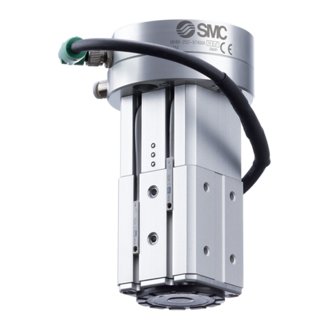
Figure 3
B
JMHZ-TF2Z397EN
Page 2 of 2
4 Settings
4.1 Finger Opening/Closing Speed Adjustment
Use a flat blade screwdriver for adjusting the metering valves.
Ensure that the restriction of the two metering valves is approximately
the same. If they differ too much, the operation can become unstable.
Figure 5
5 How to Order
Refer to the customer drawings for ‘How to Order’.
6 Outline Dimensions
Refer to the customer drawings for outline dimensions.
7 Maintenance
7.1 General maintenance Caution
Not following proper maintenance procedures could cause the product
to malfunction and lead to equipment damage.
If handled improperly, compressed air can be dangerous.
Maintenance of pneumatic systems should be performed only by
qualified personnel.
Before performing maintenance, turn off the power supply and be sure
to cut off the supply pressure. Confirm that the air is released to
atmosphere.
After installation and maintenance, apply operating pressure and
power to the equipment and perform appropriate functional and
leakage tests to make sure the equipment is installed correctly.
If any electricalconnections are disturbed during maintenance, ensure
they are reconnected correctly and safety checks are carried out as
required to ensure continued compliance with applicable national
regulations.
Do not make any modification to the product.
Do not disassemble the product, unless required by installation or
maintenance instructions. Warning
When air grippers are removed for maintenance, first confirm that
measures are in place to prevent any workpieces from dropping, run-
away of equipment. Then cut off the supply pressure and electric
power and exhaust all compressed air from the system using the
residual pressure release function. When the equipment is restarted,
proceed with caution after confirming that appropriate measures are in
place to prevent cylinders from sudden movement.
Do not allow people to enter or place objects in the carrying path of the
air gripper. Otherwise injury or accident may occur.
Do not put hands in between the air gripper fingers or attachments.
8 Limitations of Use
8.1 Limited warranty and disclaimer/compliance requirements
Refer to Handling Precautions for SMC Products.
9 Product Disposal
This product shall not be disposed of as municipal waste. Check your
local regulations and guidelines to dispose this product correctly, in order
to reduce the impact on human health and the environment.
10 Contacts
Refer to www.smcworld.com or www.smc.eu for your local
distributor/importer.
URL : https:// www.smcworld.com (Global) https:// www.smc.eu (Europe)
SMC Corporation, 4-14-1, Sotokanda, Chiyoda-ku, Tokyo 101-0021, Japan
Specifications are subject to change without prior notice from the manufacturer.
© 2021 SMC Corporation All Rights Reserved.
Template DKP50047-F-085M
magnified view of the
matering valve
Adjustment groove
(for flat blade screwdriver)

Other SMC Networks Robotics manuals

SMC Networks ZXP7 01-X1 Series User manual

SMC Networks

SMC Networks ZXP7 01-X1 Series User manual

SMC Networks JMHZ2-16D-X7400B-ASSISTA User manual

SMC Networks

SMC Networks JMHZ2-16D-X7400B-ASSISTA User manual

SMC Networks MHM-25D-X7400A-DTP-N User manual

SMC Networks

SMC Networks MHM-25D-X7400A-DTP-N User manual

SMC Networks FAS-200 User manual

SMC Networks

SMC Networks FAS-200 User manual

SMC Networks JMHZ2-16D-X7400B-TM User manual

SMC Networks

SMC Networks JMHZ2-16D-X7400B-TM User manual

SMC Networks JMHZ2-16D-X7400B-DTB-N User manual

SMC Networks

SMC Networks JMHZ2-16D-X7400B-DTB-N User manual

SMC Networks JMHZ2-16D-X7400B-HC10-N User manual

SMC Networks

SMC Networks JMHZ2-16D-X7400B-HC10-N User manual

SMC Networks MHM-25D-X7400A-CRX User manual

SMC Networks

SMC Networks MHM-25D-X7400A-CRX User manual

SMC Networks MHM-25D-X7400A User manual

SMC Networks

SMC Networks MHM-25D-X7400A User manual

SMC Networks JMHZ2-16D-X7400B User manual

SMC Networks

SMC Networks JMHZ2-16D-X7400B User manual

SMC Networks MHM-25D-X7400A-TM User manual

SMC Networks

SMC Networks MHM-25D-X7400A-TM User manual

Popular Robotics manuals by other brands

Arexx YETI manual

Arexx

Arexx YETI manual

ROBOTIQ HAND-E quick start guide

ROBOTIQ

ROBOTIQ HAND-E quick start guide

JOOLA Robot SHORTY operating instructions

JOOLA

JOOLA Robot SHORTY operating instructions

Omron CR_UDG4_NR user manual

Omron

Omron CR_UDG4_NR user manual

bionicbird Metabird instruction manual

bionicbird

bionicbird Metabird instruction manual

Husqvarna DXR 145 Operator's manual

Husqvarna

Husqvarna DXR 145 Operator's manual

V-tech JOTBOT 5537 instruction manual

V-tech

V-tech JOTBOT 5537 instruction manual

Pro's Kit Probbie II Assembly & installation manual

Pro's Kit

Pro's Kit Probbie II Assembly & installation manual

MD SPORTS TT218Y18001 Assembly instructions

MD SPORTS

MD SPORTS TT218Y18001 Assembly instructions

MD SPORTS 1642124 Assembly instructions

MD SPORTS

MD SPORTS 1642124 Assembly instructions

MIR MiR100 manual

MIR

MIR MiR100 manual

Toshiba TH650A-IP instruction manual

Toshiba

Toshiba TH650A-IP instruction manual

HEBI Robotics X Series Assembly instructions

HEBI Robotics

HEBI Robotics X Series Assembly instructions

Mab Robotics MD80 x CANdle user manual

Mab Robotics

Mab Robotics MD80 x CANdle user manual

Rover Robotics Open Rover quick start guide

Rover Robotics

Rover Robotics Open Rover quick start guide

AIBrain Tyche user guide

AIBrain

AIBrain Tyche user guide

Universal Robots 3PE Teach Pendant installation guide

Universal Robots

Universal Robots 3PE Teach Pendant installation guide

Innovation First HEXBUG BATTLEBOTS WITCH DOCTOR 413-5186 instructions

Innovation First

Innovation First HEXBUG BATTLEBOTS WITCH DOCTOR 413-5186 instructions

manuals.online logo
manuals.online logoBrands
  • About & Mission
  • Contact us
  • Privacy Policy
  • Terms and Conditions

Copyright 2025 Manuals.Online. All Rights Reserved.