Smith Manufacturing X3 User manual

X3 Hydraulic
Heavy duty triple head remover
User Manual
(954) 941-9744
www.SMITHMFG.com
MANUFACTURING
Cutters / Removers / Parts / Support
1-800-653-9311
www.SmithMfg.com
Phone: 954-941-9744 • Fax: 954-545-0348

SMITH Manufacturing 1-954-941-9744 www.SmithMfg.com
X3
VERSION 6/2013
Hydraulic
SMITH Manufacturing 1-954-941-9744 www.SmithMfg.com
INTRODUCTION
2
Congratulations on purchasing the
X3™from SMITH Mfg. Company.
Page Contents
2 Index / Introduction
3 Safety Guidelines
4 Your X3 Heavy Duty Remover
5 Controls Descriptions / Attaching to Skid Loader
6 Safety Guidelines
7 Substrate Removal
8 Storage, Ordering, and Warranty Claims
9 Troubleshooting
10 Maintenance Check List
11-12 Cutter Head Installation and removal
13 Depth and Width of Cut
14-15 Belt Removal
16-17 Bearing Replacement
18-19 Maintenance Log
20 Limited Equipment Warranty
21 Warranty Activation
INDEX
The X3™ (patent pending) is an triple head
Eraser that attaches to most skid loader,
tractor or truck body for removing striping, curing
compounds, and more while leaving the road in
a natural condition. Powered by gas, diesel, or
hydraulics, the X3™ allows a single operator to
remove from 8” - 20” wide (when engaging the
swivel attachment with outboard wheel
assembly). The X3™ is a versatile, full-featured
eraser that grows as your needs grow, with
additional units: inline for faster removal, or
offset for wider removal. Designed to remove with
a unique swivel wheel sweeping removal method
pattern, the X3™ feathers the substrate edges to
eliminate the grooving pattern or "ghost line".
Select your style of removal tool: from our
gentle action set of 3 steel pin cutters, to our
aggressive, 72 pin tungsten carbide, or our 144 pin
carbide gentle abrading and NEW, 216 pin
tungsten carbide pin cutter for concrete.
Diamond Cup Wheel, Wire Brushes, or
Tungsten Carbide Mini-Pick Heads are
available for your other surface preparation and
line removal needs..
You will obtain years of satisfying service when
your machine is properly used and maintained.
Please read completely this guide and parts list
manual to assure your REMOVAL SUCCESS.
If you have any questions about the operation of
your machine or would like to order replacement
parts, please contact your SMITH Dealer directly,
or call SMITH at 1-800-653-9311 or
(954) 941-9744 for the name of your local dealer.

SMITH Manufacturing 1-954-941-9744 www.SmithMfg.com
SMITH Manufacturing 1-954-941-9744 www.SmithMfg.com
VERSION 6/2013
X3
Hydraulic
3
UNCRATING EQUIPMENT
When you uncrate your equipment, make certain
that the machine has not been damaged and that
all fasteners and guards are properly tightened.
Battery, oil, and fuel (if non-hydraulic) were not
included in shipment. No hose ttings were
included on hydraulic models. Please note that
some assembly of your X3™ may be required
before use to include the bobtach plates. .
Your machine may not have been shipped
assembled with cutters and other accessories.
Assembly may be required.
BEFORE START-UP,
READ THIS..
REMEMBER: Only authorized, experienced and
properly trained personnel should operate this
equipment. Operating personnel should
practice safety at all times and ear protective
gear (gloves, goggles, safety vests, ear plugs,
steel-toe shoes, etc.)
Please read all operating instructions, and be
completely familiar with your equipment before
operating. When in doubt, please contact SMITH
Manufacturing Customer Service for operational
details. This Owner’s Manual will guide you
through the removal process, from start to
nish, and show you how to care for your
machine. Hydraulic Systems must have
adequate pressure and volume to operate
correctly.
SMITH Manufacturing 1-954-941-9744 www.SmithMfg.com
X3
VERSION 6/2013
Hydraulic
SMITH Manufacturing 1-954-941-9744 www.SmithMfg.com
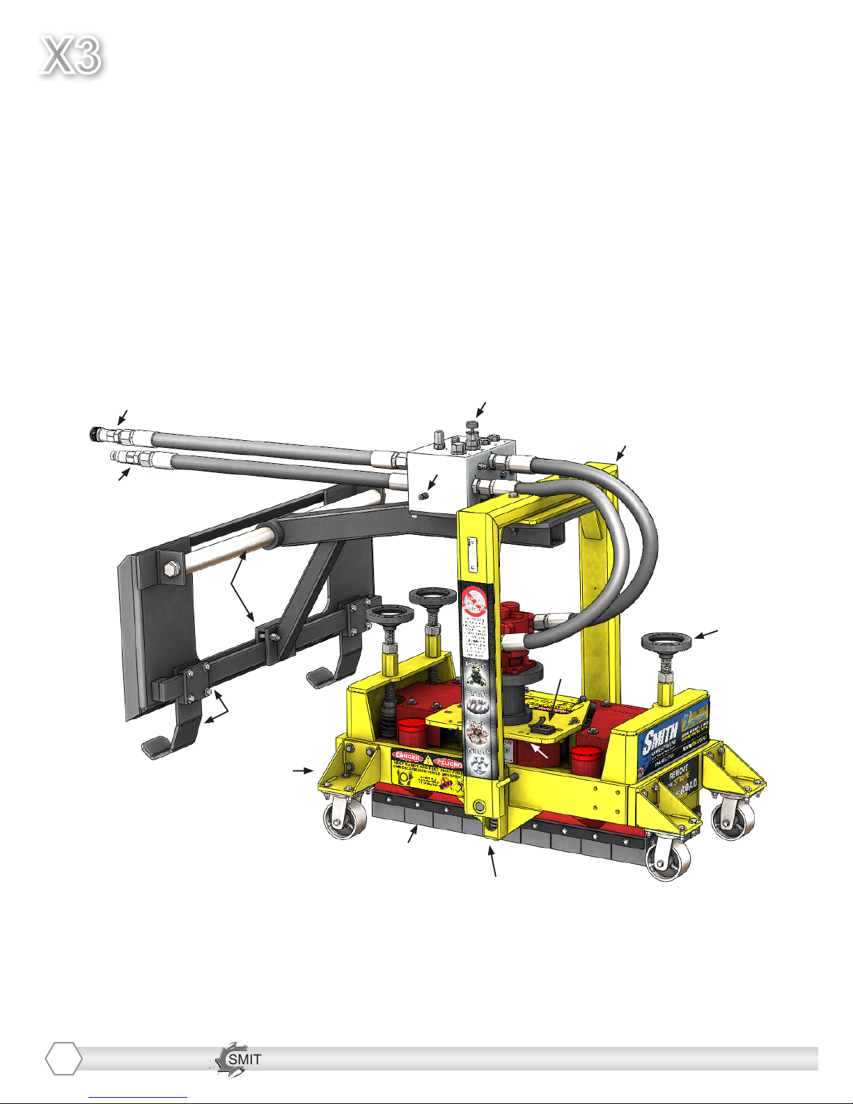
YOUR X3TM HEAVY DUTY REMOVER
Please take time to familiarize yourself with the X3™’s
controls, as well as some of the features of your new machine.
Read the engine manual before preparing the engine for starting.
4
C
E
G
H
H
I
J
K
L
M)
D
B
A
F

SMITH Manufacturing 1-954-941-9744 www.SmithMfg.com
SMITH Manufacturing 1-954-941-9744 www.SmithMfg.com
VERSION 6/2013
X3
Hydraulic
CONTROLS DESCRIPTIONS
5
• A) TANK RETURN LINE - Female quick
connect
• B) SUPPLY LINE - Male quick connect
• C) BOBTACH PLATE - Attachment to skid
steer. Machine may be located anywhere
along bar. Loosen clamp bolts (2) to adjust
the unit side to side.
• D) DIAGNOSTIC PORT - Contains 3
pressure indicating ports for diagnostic
purposes
• E) CUTTER SPEED CONTROL - Do NOT
exceed MAX of 2200 RPM.
• F) YOKE - Should be perpendicular to the
ground during operation.
• G) TACH/HOUR METER - Check before and
during operation to make sure safe running
speeds are being maintained.
• H) CUTTER HEIGHT CONTROL - 1 of 3,
adjust together.
• I) BOBTACH FIELD LEGS - Support
machine when not attached to skid steer.
May be located anywhere along bar. Loosen
clamp bolts (4) to adjust the legs side to side.
• J) SIDE MOUNT LOCATION - Wheels may
be mounted on the sides to avoid build up
from debris.
• K) DEBRIS SKIRT - Protects from ying
debris.
• L) YOKE SPRING - Check skid steer down
pressure here.
• M) TENSIONING SCREWS - Located under
the plate, adjust belt tension here.
ATTACHING TO SKID
LOADER
1. Complete pre-operational check and
complete and return warranty card.
2. Conrm skid-loader has proper mounting
brackets to t the supplied Bobtach plate. If
not, obtain for your local ski loader supplier and
replace plate on supplied with your X3 with the
plate for your skid loader.
3. If you are going to front mount to a truck,
contact SMITH for mounting instructions. The
unit can also be mounted ot the side of your
equipment as well.
4. Check the levelness of the 4 sets of caster
wheels and the bobtach assembly. Add spacers
to align, if required.
5. Make certain the machine is off the ground
and/or cutters are off the ground before start-up.
6. Get familiar with the drive system, how to
maintain and replace the drive belt and cutters.

SMITH Manufacturing 1-954-941-9744 www.SmithMfg.com
X3
VERSION 6/2013
Hydraulic
SMITH Manufacturing 1-954-941-9744 www.SmithMfg.com
6
SAFETY GUIDELINES
• Never start the machine with cutters in down
position.
• Never operate machine without Rubber Skirt.
• Never operate machine without Belt Cover.
• ·· Do not operate in an explosive atmosphere,
near combustible materials or where gas fumes
may not be properly dispersed.
• Never leave the machine running unattended.
SAFETY GUIDELINES
The X3 requires a hydraulic supply
source capable of 3000 psi and delivering a
MINIMUM of 28 gpm.
Cutters should never exceed 2200 RPM
• Always wear safety glasses, steel toed shoes,
work gloves, earplugs, respirator.
• Always check to be sure all fasteners and
cutter assemblies are locked tight.
• Keep hands and feet clear of Cutter Assembly.
• Make certain the two Weights are fastened
securely before operation.
• Repair any fuel leaks immediately (Hydraulic
and Gas Models)
• Never operate machine with the unit off the
ground in an unsafe position.
• Never let anyone near Cutting Assembly
during operation. Under no circumstances may this machine be
modied from its original design without the
permission of the manufacturer in writing.
Non-authorized modications can lead to serious
injury or death.

SMITH Manufacturing 1-954-941-9744 www.SmithMfg.com
SMITH Manufacturing 1-954-941-9744 www.SmithMfg.com
VERSION 6/2013
X3
Hydraulic
7
SUBSTRATE REMOVAL 6 STEPS FOR LONGER
CUTTER LIFE
1) Protect the bearings with clean, oiled felt
Seals*.
2) Do not pinch felt seals when installing
cutters*.
3) Replace bearings and felt seals when worn*.
4) Change rubber bushings on engine plate
and spindle assembly after 50 hours use.
5) Never drop cam lever during grinding
operations.
Lower cutters gently onto road surface.
6) Purchase a second spindle mount with
removal tools outtted and rotate out daily.
*Pin cutter only
BEGINNING REMOVAL OPERATION: Move
your skid loader (vehicle) in the direction
of removal before lowering the unit on the
ground. It is recommended that to avoid
damage to the cutters, that they be lowered
gently to the road surface while moving
forward/backwards. This will insure that you
will achieve best nish (eliminate “crop-circle”
appearance) and not damage the cutters.
IMPORTANT NOTE ON REMOVAL DEPTH:
It is also recommended that the cutters be
lowered to contact the road surface just
enough to compete the removal process.
Excess downpressure creates excess wear
on all the moving parts. The unit weighs
approximately 600 Lbs. This should be
sufcient weight to hold the cutter heads
against the work surface. Should the desired
results not meet your expectations, consider
resetting the engine speed (RPM’s) to the
correct speed or reducing forward motion
speed to an acceptable level.
ENDING REMOVAL OPERATION: Raise
the unit above ground prior to stopping. The
X3 “hard-stops” so make certain everyone is
clear when shutting down.

SMITH Manufacturing 1-954-941-9744 www.SmithMfg.com
X3
VERSION 6/2013
Hydraulic
SMITH Manufacturing 1-954-941-9744 www.SmithMfg.com
STORAGE
Store machine upright in a cool, dry, and
well-ventilated area. Make sure not to
damage the hydraulic connections which
could allow air or water into the system.
ORDERING
To ensure product safety and reliability,
and to maintain your warranty, always use
genuine replacement cutters and partsfrom
SMITH when making repairs to equipment.
When oredering please specify the model and
serial number of the machine. In addition, give
a part number, description, and quantity as
listed on your parts list.
If you have any questions about the operation
of your machine or would like to order
replacement parts, contact your SMITH
Manufacturing representative directly.
Contact 1-800-653-9311 (954-941-9744)
for information.
Visit our website at
www.smithmfg.com
WARRANTY CLAIMS
The manufacturer reserves the right to
change or improve the machine design with-
out assuming any obligation to update any
products previously manufactured before
this manual. It is the customer’s responibility
to complete the warranty card and mail it to
the seller within 10 days from date of pur-
chase. If a failure occurs during the warranty
period, the customer must contact the seller
to determine the appropriate action.
Any and all transportation charges are to
be borne by the purchaser.
8
SMITH Manufacturing 1-954-941-9744 www.SmithMfg.com
SMITH Manufacturing 1-954-941-9744 www.SmithMfg.com
VERSION 6/2013
X3
Hydraulic
TROUBLESHOOTING
PROBLEM
Possible Reason(s)/Solution(s)
CUTTERS WEARING
UNEVENLY/PREMATURELY
Cutter head is too low
Material Build-up
Bearings may be worn
Wrong cutters for
application
CUTTERS SHAFT BREAKAGE
UNEVENLY/PREMATURELY
Cutter head is too low
End plates or bushings worn
Over 40 hours service-life
EXCESS VIBRATION
Bearing worn
Cutter head contacting ground
Wheels worn out
MACHINE JUMPS
ERRATICALLY
Cutter head is hitting ground
RPM is too low
Surface is severely uneven
DRIVE BELT WEARING
PREMATURELY
Pulley is misaligned
Wrong belt
*Motor repair and warranty issues
are handled directly
by your local engine service center.
For any other problems or questions,
please contact your local representative
or
SMITH Mfg today at 800-653-9311
or
(954) 941-9744.
9
Cutter head is hitting ground

SMITH Manufacturing 1-954-941-9744 www.SmithMfg.com
X3
VERSION 6/2013
Hydraulic
SMITH Manufacturing 1-954-941-9744 www.SmithMfg.com
MAINTENANCE CHECK LIST
• Keep a coating of grease on the drive shaft
and threads for easy installation or removal,
and for longer hex bushing life.
• Check all fasteners and re-tighten, since the
machine will vibrate the fasteners loose if they
are not secured. Use locktight.
• Check the Drive belt for wear, and adjust
(tension), or replace as required.
After replacing belts, check for proper tension:
• Adjust Idler to tension belt. Do not over
tighten.
• Check that the pulleys are aligned properly
to ensure the belts are running true.
10
• The inside housing must be clean, and
remove any build-up from inside the cage so
cutters and drum rotate freely.
MAINTENANCE SCHEDULE
DAILY
Oil felt seals
Clean dirt from equipment
WEEKLY
Clean caster wheels
Grease slide bar
Inspect guards
EVERY 16 HRS OF OPERATION
Check cutter bearings
Check drive bearings
Check rubber bushings
EVERY 50 HRS OF OPERATION
Check springs
Check meters
Order spare parts
Before beginning servicing on any
X3 unit, DISCONNECT FROM
HYDRAULIC SUPPLY SOURCE

SMITH Manufacturing 1-954-941-9744 www.SmithMfg.com
SMITH Manufacturing 1-954-941-9744 www.SmithMfg.com
VERSION 6/2013
X3
Hydraulic
REMOVING
CUTTER HEADS
The X3 (patent pending) machine utilizes
multiple (maximum of 3) rotary heads to
increase forward speed or width in removal
of trafc lines or surface preparation. Re-
gardless of the type head chosen, correct
head installation and adjustment will ease
removal and ensure long cutter life.
Excess pressure increases wear on the
removal heads, belt and bearing,
and yields short life cycles.
Before beginning servicing on any
X3 unit, DISCONNECT FROM
HYDRAULIC SUPPLY SOURCE
1. Raise the X3 to a height where the cutters
are easily accessible.
2. Use a wooden block or something similar
to lock down the rotation to one of the cutter
heads (this will lock down rotation to all).
3. Use an impact gun with a 24mm socket to
remove the three hex head bolts from one
head and slide cutter head downward, off of
shaft. Repeat for remaining cutter heads.
4. It is recommended that the rubber
bushings that cushion the backplate and
hub connector to the hub heads be replaced
everytime the cutter head is removed.
*TIP: SMITH recommends owning
an extra drum loaded with cutter for
rapid job-sight
11
3)
Rubber Bushings
CAUTION: DO NOT DROP CUTTERS ON
SURFACE, DOING SO WILL POSSIBLY
DAMAGE PINS, BEARING AND BODY!
SMITH Manufacturing 1-954-941-9744 www.SmithMfg.com
X3
VERSION 6/2013
Hydraulic
SMITH Manufacturing 1-954-941-9744 www.SmithMfg.com
12
INSTALLING
CUTTER HEADS
1. Install the number of heads desired (from
one to three) on the spindles using either a
24mm socket or wrench. It is recommended
to use an impact gun if available.
2. Adjust the cutter heads by loosening the
jam nuts on the Acme elevation screws
located on both ends of the machine.
3. Turn the elevation knobs up about two
turns to ensure the Cutter heads do not hit.
Before beginning servicing on any
X3 unit, DISCONNECT FROM
HYDRAULIC SUPPLY SOURCE
5. Begin adjusting the heads downward and
using a piece of thick paper, adjust until the
heads are touching the paper evenly on all
sides.
6. Next you may lower the unit about 1 line
on the knobs so that the cutters touch by
a slight amount. Be sure to lower all cutter
heads evenly.
7. AT THIS POINT RECONNECT THE
SPARKPLUGS BEFORE CONTINUING.
8. Raise the X3™ off the ground slightly (½”
or so) to ensure the cutters do not put
grooves in the road surface when starting
the engine. Allow the engine to warm
up for a minute or two and then set to the
correct RPM for the cutters you have
installed (Rotary cutters = 2000-2200 RPM
(engine)). Incorrect setting of RPM will
damage cutters or drive belt so be sure it is
correct before proceeding.
9. After sufcient warm up time, begin
forward motion and lower the X3™ at the
same time. Remember: if you stop the
forward motion, the unit should be raised
again to prevent road surface damage. If
you cannot elevate the unit initially to start
the engine, you may put a couple of pieces
of ¼” plywood or some other suitable shim
under the wheels to raise the cutters off the
ground. This way the unit can be started
above the surface, then rolled off the wood
to begin erasing the line.
2)
4. For the initial installment, fold the rubber
skirt upwards and tape it to the frame. This
will allow you to view the cutters when
initially setting the height.
3)

SMITH Manufacturing 1-954-941-9744 www.SmithMfg.com
SMITH Manufacturing 1-954-941-9744 www.SmithMfg.com
VERSION 6/2013
X3
Hydraulic
SETTING DEPTH OF CUT
Lower cutters in a downward motion just
enough to do the job. Too much pressure
will wear the cutters out faster and leave a
much more severe cut on the surface.
Ideally, you should add slightly more
pressure to the rear cutters than the front.
This will allow the front cutters to remove
the material and the rear will nish the job.
Observe the tachometer to ensure
speed with cutters in use matches the
recommended speed for best cutter life.
Adjust as required using the speed control
knob.
13
IMPORTANT NOTE
Excess down pressure creates excess wear
on all the moving parts. The unit weighs
approximately 600 Lbs. This should be
sufcient weight to hold the cutter heads
against the work surface. Should the
desired results not meet your expectations,
consider resetting the engine speed (RPM’s)
to the correct speed or reducing forward
motion speed to an acceptable level.
RECOMMENDED SPEEDS
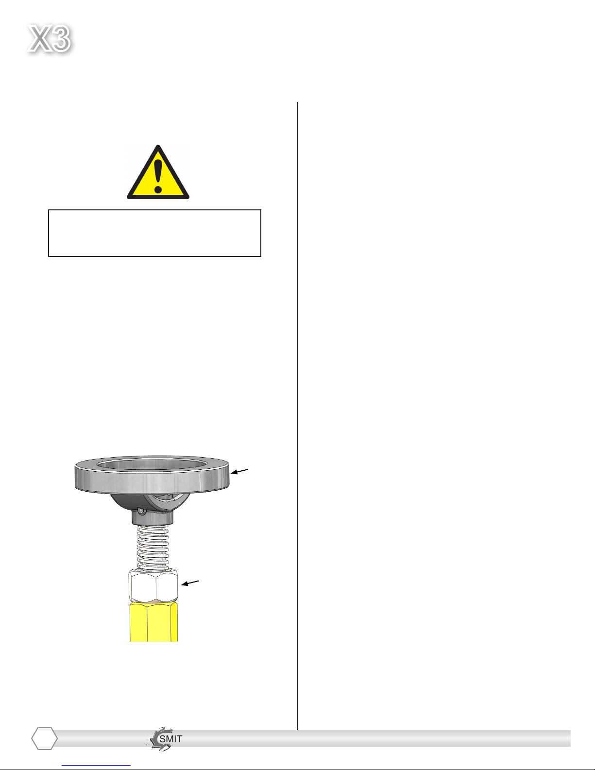
SETTING WIDTH OF CUT
The X3™ allows the unit to be swiveled up
to 30° either left or right to increase the
cutting path width. Move the caster wheel
assembly from inboard to outboard when
removing at wider paths.
1. Loosen the center swivel bolt at the end
of the attachment arm and then loosen the
outer two bolts using two 3/4” sockets or
wrenches. Swivel the unit either right or left
to the desired angle and retighten the bolts.
1)
You may wish to elevate the leading edge
side of the cutters just slightly to increase
erasing capacity.
The hydraulic model X3 best performs at
2000-2200 RPM.

SMITH Manufacturing 1-954-941-9744 www.SmithMfg.com
X3
VERSION 6/2013
Hydraulic
SMITH Manufacturing 1-954-941-9744 www.SmithMfg.com
BELT REMOVAL
The X3 is equipped with a PolyChain GT2
drive belt or a multi groove (banded) “V”
belt in a serpentine arrangement. This
allows all three heads to turn in the same
direction to minimize parts inventory of
heads and drive components.
Tools required:
1. 1.5” wrench
2. 7/16” socket or wrench
3. 9/16” socket or wrench
4. 3/16” hex key
14
Before beginning servicing on any
X3 unit, DISCONNECT FROM
HYDRAULIC SUPPLY SOURCE
1. Raise the cutter heads off the ground by
turning the 3 level adjusters all the way up.
Loosen the jam nuts using the 1.5” wrench
and raise the three elevating screws all the
way up. This allows access to the button
head screws holding the upper and lower
covers on.
1)
2. Remove the auxiliary belt cover over
the engine pulley using a 7/16” socket or
wrench.
2)
3. Remove the main belt guards using a
9/16” socket or wrench.
4. Once the beltguards are out of the way,
remove the 4 motor plate screws using a
9/16” socket or wrench.
4) 5)
SMITH Manufacturing 1-954-941-9744 www.SmithMfg.com
SMITH Manufacturing 1-954-941-9744 www.SmithMfg.com
VERSION 6/2013
X3
Hydraulic
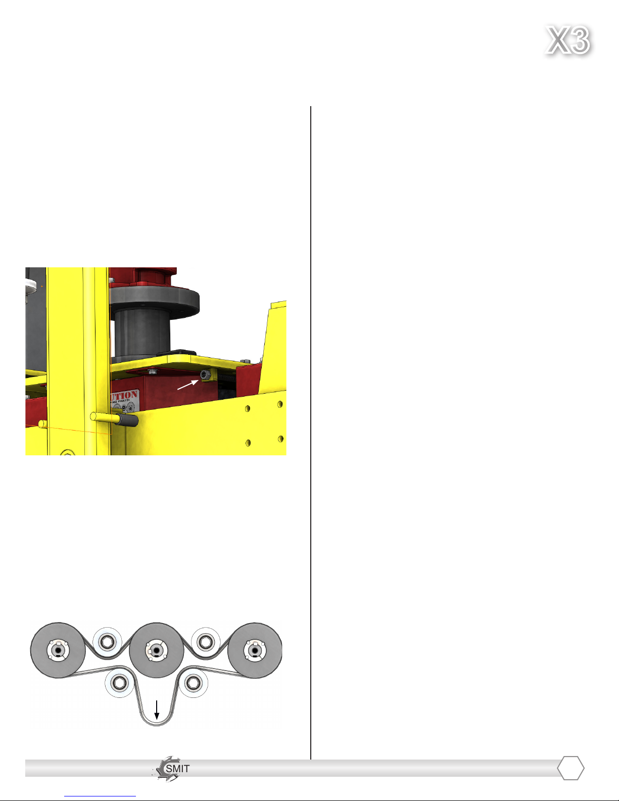
BELT REMOVAL
CONTINUED
5. To loosen the tensnion on the belt,
locate and loosen the two jam nuts on
the adjusting screws for under the motor
mount plate using a 9/16” socket or wrench
and then using a 3/16” hex key back out
the tensioning screws until the drive belt is
completely loose.
7)
8. Lower the motor and belt cover and as
you lower it use the string to pull the belt
over the motor pulley.
9. Using the tension screws begin to
tighten the belt by moving the motor away
from the center of the unit.
10. After the belt has been propely
tightened, reconnect the X3 to the skid
streer and allow it to run for 15 to 20
seconds to allow the belt to set into the
grooves of the pulleys correctly.
It is better to tension the belt tightly
rather than loosely. Loosely tightened belts
will cause the belt to ride out of the pulley
grooves and snap.
11. Reattach all the covers and the unit will
be ready for operation. Periodic tensioning
of the belt will ensure long belt life.Recheck
belt tension again after 30 minutes of use.
15
5)
6. Lift the entire motor mount plate
assembly off and set it aside to allow
access to the drive belt.
7. To install the new belt, remove the old
belt and slide the new one around the three
pulleys and four idlers. Tie a piece of string
around the belt to pull it out towards the
motor pulley at reassembly time.
sing the tension screws begin to
tighten the belt by moving the motor away
from the center of the unit.
10. After the belt has been propely
tightened, reconnect the X3 to the skid
streer and allow it to run for 15 to 20
seconds to allow the belt to set into the
grooves of the pulleys correctly.
It is better to tension the belt tightly
rather than loosely. Loosely tightened belts
will cause the belt to ride out of the pulley
grooves and snap.
11. Reattach all the covers and the unit will
be ready for operation. Periodic tensioning
of the belt will ensure long belt life.Recheck
belt tension again after 30 minutes of use.

SMITH Manufacturing 1-954-941-9744 www.SmithMfg.com
X3
VERSION 6/2013
Hydraulic
SMITH Manufacturing 1-954-941-9744 www.SmithMfg.com
BEARING REPLACEMENT
To remove the drive bearing assemblies
follow the rst procedure to remove the
drive belt. It may needed to completely
remove the motor to have enough working
room. This gives you access to the
bearing assemblies. Note that the
assemblies are matched in sets. The
machine SN and the established length are
stamped on the housing. This insures all
three heads hit the working surface
at the same time.
ORDERING INSTRUCTIONS
MATCH SERIAL NUMBERS
TO ASSURE CORRECT PART!
If ordering a new bearing assemblies,
please be sure you when ordering. identify
the machine serial number. We will send
the correct part and dimension to insure
you machine is tted with a matching
housing.
Tools required:
1. Two 3/4” socket or wrench
2. Flat head screw driver
3. 3/16” hex key
If it has not been done so, follow the
instructions to remove the cutter heads on
pg. 11 before proceding.
1. Follow the instructions on pg. 15 to
remove belt guards, drive belt, and to
remove the hydraulic motor and set it aside
until the machine looks as shown.
16
4. After the collar is removed, use the 3/16”
hex key to remove the two set screws that
are locking down the pulley.
2. At this point there is full access to the
machine drive components to service them
as needed.
3. To service the main bearing housings,
the drive pulleys must be removed. To do
this use a 3/16” hex key to remove the
collar
3)

SMITH Manufacturing 1-954-941-9744 www.SmithMfg.com
SMITH Manufacturing 1-954-941-9744 www.SmithMfg.com
VERSION 6/2013
X3
Hydraulic
BEARING REPLACEMENT
CONTINUED
4)
5. Use one of the set screws and thread it
into the middle hole to back out the
bushing as shown below.
5)
6. Once the pulley is removed, use a 13/16”
socket and wrench to remove the bearing
housings from the machine.
Bearing housing assembly components
shown below:
6)
17
ASSEMBLY
PN: PM03010000
Bearing housing assembly components
shown below:
On the HYDRAULIC MODEL, the X3 has a
motor mount bearing assembly as shown
below.
ASSEMBLY
PN: X3.00.310A

SMITH Manufacturing 1-954-941-9744 www.SmithMfg.com
X3
VERSION 6/2013
Hydraulic
SMITH Manufacturing 1-954-941-9744 www.SmithMfg.com
MAINTENANCE LOG
18

SMITH Manufacturing 1-954-941-9744 www.SmithMfg.com
SMITH Manufacturing 1-954-941-9744 www.SmithMfg.com
VERSION 6/2013
X3
Hydraulic
MAINTENANCE LOG
WARRANTY CLAIMS
The manufacturer reserves the right to change or improve the machine design without assuming any
obligation to update any products previously manufactured before this manual. It is the customer’s
responsibility to complete the warranty card and mail it to the seller within 10 days from the date
of purchase. If a failure occurs during the warranty period, the customer must contact the seller
to determine the appropriate action. Any and all transportation charges are to be borne by the
purchaser.
19

SMITH Manufacturing 1-954-941-9744 www.SmithMfg.com
X3
VERSION 6/2013
Hydraulic
SMITH Manufacturing 1-954-941-9744 www.SmithMfg.com
Limited Equipment Warranty
All statements, technical information and recommendations contained in SMITH’s literature are based on tests believed to be reliable, but the accuracy
or completeness thereof is not guaranteed and the following is made in lieu of all warranties, expressed or implied. SMITH warrants all equipment or part
referenced in this document which is manufactured by SMITH and bearing its name to be free from defects in material and workmanship on the date of
sale to the original purchaser under normal use and maintenance as herein provided. This warranty does not apply to components manufactured by others
such as, but not limited to, bearings and engines; such components that may or may not have their own warranties.
With the exception of any special, extended, or limited warranty published by SMITH, SMITH will, for a period of three months (90 days) from the
date of sale or up to ve hundred (500) hours of use by buyer, whichever shall occur rst; repair or replace any part of the equipment determined by
SMITH to be defective. This warranty applies only when the equipment or part is installed, operated and maintained in accordance with SMITH’s written
recommendations.
SMITH’s sole obligation for any breach of warranty or breach of contract for defects, deliberate or accidental omissions, shall be limited to repairing,
replacing or allowing credit for, at SMITH’s option, any part which, under normal and proper use and maintenance, proves defective in material or
workmanship within warranty period, provided, however, that notice of any such defect or omission and satisfactory proof thereof is promptly given by
buyer to SMITH, and thereafter, such defective part is returned to SMITH with transportation charges prepaid, and SMITH’s examination proves such part
to have been defective. This warranty does not obligate SMITH to bear any transportation charges or personnel time in connection with the replacement
or repair of defective parts. This warranty does not obligate SMITH to bear any expense for travel time or of personnel in connection with any service calls.
SMITH will not, in any event, be liable to the user for any consequential damages arising out of this sale for the loss of use, lost prots or revenue, interest,
lost goodwill or work stoppage. SMITH shall not be liable for any injury, loss or damage, direct or consequential, arising out of the use or the inability to use
the product or for environmental claims. It being understood that SMITH has no means of controlling the products nal use; therefore, it shall be buyer’s
responsibility to determine suitability of product for intended use and buyer assumes all risks and liabilities whatsoever, in connection therewith. In no event
shall SMITH be liable for consequential or special damages. Used products are sold on an “as is” basis, and there is no implied warranty of merchantability
or of tness for a particular purpose, unless made in writing by an ofcer at SMITH’s ofce.
This warranty does not cover, and SMITH shall not be liable for general wear and tear, or any malfunction, damage or wear caused by faulty installation,
misapplication, abrasion, corrosion, inadequate or improper maintenance, negligence, accident, tampering, or substitution of non-SMITH component parts.
Nor shall SMITH be liable for malfunction, damage or wear caused by the incompatibility of SMITH equipment with structures, accessories, equipment
or materials not supplied by SMITH, or the improper design, manufacture, installation, operation or maintenance of structures, accessories, equipment
or materials not supplied by SMITH. This warranty does not apply in respect to damages to any product or accessory or attachment thereof caused by
overloading or other misuse, neglect or accident, nor does this warranty apply to any product or accessory or attachment thereof, which has been repaired
or altered in any way which, in the sole judgment of SMITH, affects the performance, stability or general purpose for which it was manufactured. In the
manufacture of buyer’s equipment, parts may be omitted or equivalent functioning equipment and components may be substituted for the original specied
equipment upon the sole judgment and discretion of SMITH.
This warranty is conditioned upon the prepaid return of the equipment claimed to be defective to an authorized SMITH Reseller for verication of the
claimed defect. If the claimed defect is veried, SMITH will repair or replace free of charge any defective parts and return of merchandise back to the
customer freight collect. If inspection of the equipment does not disclose any defect in material or workmanship, repairs will be made at a reasonable
charge, which charges may include the costs of parts, labor and transportation.
THIS WARRANTY IS EXCLUSIVE AND IS IN LIEU OF ANY OTHER WARRANTIES, EXPRESS OR IMPLIED, INCLUDING BUT NOT LIMITED TO
WARRANTY OF MERCHANTABILITY OR WARRANTY OF FITNESS FOR A PARTICULAR PURPOSE.
SMITH’s sole obligation and buyer’s sole remedy for any breach of warranty shall be as set forth above. The buyer agrees that no other remedy (including,
but not limited to, incidental or consequential damages for lost prots, lost sales, injury to person or property, or any other incidental or consequential loss)
shall be available. Any action for breach of warranty must be brought within two (2) years of the date of sale.
SMITH MAKES NO WARRANTY, AND DISCLAIMS ALL IMPLIED WARRANTIES OF MERCHANTABILITY AND FITNESS FOR A PARTICULAR
PURPOSE, IN CONNECTION WITH ACCESSORIES, EQUIPMENT, MATERIALS OR COMPONENTS SOLD BUT NOT MANUFACTURED BY SMITH.
These items sold, but not manufactured by SMITH (such as electric motors, switches, hose, etc.), are subject to the warranty, if any, of their manufacturer.
SMITH will provide purchaser with reasonable assistance in making any claim for breach of these warranties. In no event will SMITH be liable for indirect,
incidental, special or consequential damages resulting from SMITH supplying equipment hereunder, or the furnishing, performance, or use of any products
or other goods sold hereto, whether due to a breach of contract, breach of warranty, the negligence of SMITH, or otherwise.
ADDITIONAL WARRANTY COVERAGE - SMITH does provide extended warranty and wear warranty for products.
Corrections - typographical or clerical errors contained herein are subject to correction by SMITH.
Assignment - buyer shall not assign or transfer this warranty without SMITH’s written consent.
Entire agreement and applicable law - the rights and obligations of SMITH and buyer shall be governed by the laws of the state of Florida, U.S.A. In force
on date hereof. The provisions hereof are intended by buyer and SMITH as a nal expression of their agreement, and are intended also, as a complete
and exclusive statement of all terms apply cable to buyer’s order. No waiver, modication, or addition to any of the terms hereof shall be binding on SMITH,
unless made in writing by an ofcer at SMITH’s ofce as stated herein. In the event of conict between buyer’s purchase order and the terms hereof, the
latter shall control. If any provisions herein are to any extent invalid or unenforceable, the remainder of the warranty shall not be effected thereby and shall
be valid and enforceable to the fullest extent permitted by law.
Legal action - buyer shall be responsible for all costs of collection of outstanding indebtedness, including but not limited to attorney’s fees and court costs
to seller. Buyer shall reimburse seller for any and all litigation expenses seller incurs as a result of an unsuccessful buyer claim. The jurisdiction and venue
of the court for any litigation, state or federal, brought by the buyer and/or seller shall be located in venue determined by seller.
Fair labor standards - seller’s products are produced in the United States and in conformity with all applicable provisions of the fair labor standards act of
1938 as amended and any regulations and orders of the United States Department of Labor issued thereunder.
All written and visual data contained in this document reects the most current product information available at the time of this publication. SMITH reserves
the right to make changes at any time without notice.
TO ORDER, contact your SMITH distributor or call 1-800-653-9311 to identify the nearest distributor.
SMITH Manufacturing Co, Inc.
1610 South Dixie Highway
Pompano Beach, FL 33060
www.smithmfg.com
20
Table of contents
Popular Industrial Electrical manuals by other brands


NKT Photonics
NKT Photonics Koheras ADJUSTIK Product guide

Wavetronix
Wavetronix Click 304 quick start guide

Nuovo
Nuovo Egg-Jet20 R5 Quick start user guide

Murata
Murata GRM188R71E332KA01 Series Reference sheet

Murata
Murata GRM0225C1ER90WA03 Series Reference sheet

Murata
Murata GRM033R60J225ME15 Series Reference sheet

Murata
Murata GRM153R60G475ME15 Series Reference sheet

Innovative Advantage
Innovative Advantage AVDS quick guide

Murata
Murata GQM1885C1H680GB01 Series Reference sheet

Minebea Intec
Minebea Intec MP 90/04 installation manual

Geokon
Geokon GK-401 instruction manual

Keysight Technologies
Keysight Technologies N5244AU- 940 Installation note