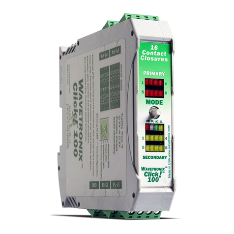
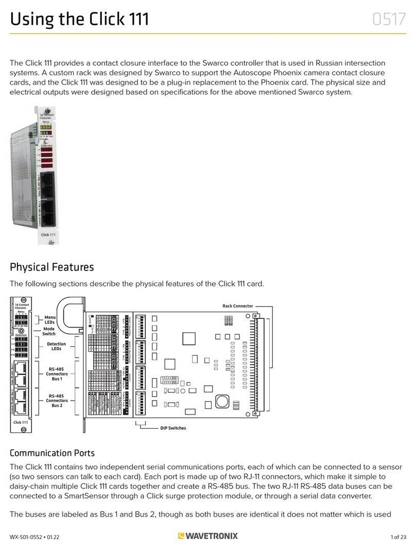
Wavetronix Click 304 User manual

1 of 8WX-501-0532 • 01.22
Using the Click 304
The Click 304 converts half-duplex RS-232 communication to RS-485 communication and vice versa. The Click
304 improves serial communication and also extends the capabilities of a serial network.
Physical Features
The Click 304 has several communication ports, as well as features for configuration.
Mode
Switch
LED Indicators
RS-485
Connector
RS-232
Connector
RS-485
Connector
T-Bus
Connector TOP
FRONT
Communication Ports
The back of the Click 304 features a 5-position connector that plugs into a T-bus connector and provides power
and RS-485 communication to the device. It also passes RS-485 communication from the Click 304 to all other
devices on the T-bus.
The top of the device has a pluggable screw terminal block that features four terminals—one -485, one +485
and two grounds—for wiring RS-485 communication. This screw terminal block can be removed for easy pre-
installation wiring. It will not be necessary, however, to wire RS-485 through the screw terminal block if the device
is connected to a T-bus with uninterrupted RS-485 communication.
0532

2 of 8WX-501-0532 • 01.22
The front of the Click 304 features a DB-9 connector and an RJ-11 connector for RS-232 and RS-485
communication. A straight-through cable can be used to connect from the RS-232 DB-9 connector to a computer
so that the device can be configured using Click Supervisor. An RJ-11 cable can be connected from the front of the
Click 304 to the front of the Click 172/174 contact closure cards.
Any data on one port will be transmitted simultaneously on all other ports.
Configuration Features
The faceplate of the Click 304 has the following three LEDs:
■ PWR (red) lights up when the device has power.
■ TD (yellow) lights up when the device is transmitting data.
■ RD (green) lights up when the device is receiving data.
The LEDs are also used to indicate operation modes, which will be discussed in the On-device Configuration
section of this document.
The front also has a push-button labeled Mode Switch, which is used to cycle the Click 304 through operation
modes. This will be discussed in the On-device Configuration section of this document.
RS-232 to RS-485 Conversion
To use the Click 304 for
On-device Configuration
The Click 304 can be configured using the push-button on the lower part of the faceplate. Press and hold the
push-button to cycle through the dierent operation modes; release the button when the desired mode is
reached. A quick press and release of the push-button will exit out of any mode and return the unit back to normal
operation. The table below and the following sections describe the dierent operating modes.
Mode LED Definition
Autobaud Green (solid) To autobaud the Click 304, press the push-button, then release when the green LED turns on.
Reset Red (flashing) To reset the Click 304 to factory defaults, press the push-button, then release when the red
LED is blinking.
Autobaud (green solid)
The Autobaud mode is used to match baud rates with an external device. By default, the device will attempt to
match baud rates with a SmartSensor on the bus; however, the device can be configured to autobaud with any
device that supports a serial interface.
While the device is autobauding, the green LED will be on while the red LED blinks. The autobaud was successful
if the red LED stays on and the green LED turns o. If the autobaud is not successful after a few minutes of trying,
the red and green LEDs will stay on indefinitely. In the case of a failed autobaud, push the push-button once to
return the device to its normal state.
Note. On certain devices, the yellow LED may replace the green LED in the autobaud process—that is, the yellow
LED will come on to select the autobaud process, the yellow LED is on during the autobaud process, etc.

3 of 8WX-501-0532 • 01.22
Factory Reset (red flashing)
The Factory Reset operation will erase all user-configured fields and the Click 304 may have to be reconfigured to
work properly in its current application. If a device is not responding and not communicating, resetting the device
may fix the problem. Once the device is responding, restore the configuration needed for its current application.
Computer Configuration
The Click 304 can be configured more exactly using the Click Supervisor software. See the knowledge base
article 0514 Installing and Using Click Supervisor for instructions on how to download and install Click Supervisor
and how to connect to your device using the software.
The Click 304 is configured using one of the following drivers (see the figure below):
Which driver you use will depend on what you need to use the device for.
If you intend to connect from your TOC to the Click 304 to a sensor, use the SmartSensor driver.
To see advanced settings, use the Expert driver. This driver, which exposes every available field for the Click 304,
should only be used under the direction of Wavetronix Technical Services.
After you have made configuration changes on a driver and saved it to the Click device, the word “current” will
appear after that driver to indicate the driver that is currently loaded onto the device.
Note. Some settings appear on multiple drivers. Changing one of those settings on any driver and saving them to
the Click device will change that setting on all other drivers it appears on.
The Backups option can be used to read configurations that have previously been saved to file.
SmartSensor Driver
The SmartSensor driver contains three tabs: Setup, About and Diagnostics. The Setup tab has the following
settings (see the figure and table below):

4 of 8WX-501-0532 • 01.22
Setting Description
Description Shows a description of the device being configured. This is only for your information and does not aect
the operation of the device.
Location Displays the location of the device being configured. This is only for your information and does not aect
the operation of the device.
Device ID Gives the ID number of the device being configured, which is used to identify the device when you are
connecting to it. By default, this number is the last five digits of the serial number, which can be found
under the About tab or on the barcode sticker on the bottom of the device. It is recommended that you
do not change this number unless another device in the network has the same ID number.
Baud Rate Allows you to change the baud rate at which the device connects to the sensor.
The About tab contains the following information about your Click 304 (see the figure and table below):
Settings Description
Driver Names the driver you are currently working with.
Serial Number Displays the serial number of your device.
Firmware Version Shows the version of firmware your device currently has installed. If Click Supervisor detects a
discrepancy between this version and the most current version it currently has access to, you will
be prompted to upgrade when you connect to the device.
Under the Diagnostics tab, you can run diagnostics on your device (see the figure below). Click the General
button to run diagnostics on the items listed below the button. If a problem is detected, the program will display a
red square next to the item in question. If no problems are detected, a green circle will appear.

5 of 8WX-501-0532 • 01.22
Once you have finished, use the menu bar at the top of the screen to save your settings, return to the Select
Driver screen, and more.
■ The Save menu allows you to save your settings. Select Save to File to save your settings to a file. Selecting this
will open a directory box, allowing you to name your settings file. This file will always be saved in the Wavetronix
folder created when you installed Click Supervisor, under Wavetronix > ClickHome > Drivers > 304 > User. You
can also select Save to Device to save your settings to your Click 304.
Note. If you do not save your settings to your Click 304, they will be lost the next time you power the device down.
■ The Tools menu contains five options for working with your device. Reset > System power cycles your device,
while Reset > Factory Default restores your device to the settings with which it was shipped. Restore will restore
the driver to the settings currently saved on the Click 304, erasing any unsaved changes. Upgrade can be used
to manually upgrade to the most current firmware for your device. Hex View changes the view of certain settings
in the driver to hexadecimal.
■ Clicking the Quit menu exits the driver and returns you to the Click Supervisor main page.
Once you have finished, click Save on the menu bar to save your settings.
Expert Driver
The Expert driver allows you to see all possible settings and fields, both those available in the SmartSensor driver
and those available only through this driver. The driver is divided into two tabs—System and Diagnostics—which
are then subdivided further.
The System > General tab combines elements of the Setup and About tabs from the other drivers (see the figure
and table below).

6 of 8WX-501-0532 • 01.22
Setting Description
Module Allows you to enter a name for the device.
Driver Names the driver you are currently working with.
Description Shows a description of the device being configured. This is only for your information and does not
aect the operation of the device.
Location Displays the location of the device being configured. This is only for your information and does
not aect the operation of the device.
Serial Number Displays the serial number of your device.
Firmware Version Shows the version of firmware your device currently has installed. If Click Supervisor detects a
discrepancy between this version and the most current version it currently has access to, you will
be prompted to upgrade when you connect to the device.
Subnet ID Shows the subnet ID number. This option is currently not available.
Device ID Gives the ID number of the device being configured, which is used to identify the device when
you are connecting to it. By default, this number is the last five digits of the serial number, which
can be found under the About tab or on the barcode sticker on the bottom of the device. It is
recommended that you do not change this number unless another device on your network has
the same ID number.
The System > Comm tab allows you to configure Click device communication (see the figure and table below).
Setting Description
Baud Rate Allows you to change the baud rate at which the device connects to the sensor.
Flow Control Is used for configuring hardware handshaking. This option is currently not available.

7 of 8WX-501-0532 • 01.22
Parity Allows you to set parity error checking.
Stop Bits Allows you to set the number of stop bits.
Data Bits Shows you the number of data bits being sent. This option currently cannot be changed.
Active Port Indicates on which port you are communicating with the sensor. This option cannot be changed.
Latency Indicates the latency between the sensor and the Click device. This option cannot be changed.
The Autobaud subtab allows you to configure how the device autobauds (see the figure and table below).
Setting Description
Command Allows you to set the command sent from the device during the autobaud process. Don’t change
these values unless instructed to by Wavetronix Technical Services.
Response Shows the response the device is expecting from the above command. Don’t change these values
unless instructed to by Wavetronix Technical Services.
SmartSensor ID Shows the ID number of the sensor with which the Click device is currently communicating. This
only shows the number after you have autobauded the Click device; when the Click device is not
communicating with a sensor, this option will display a 0.
Server/Client Allows you to set whether the device is a server or client in a point to multipoint setup. (This option is
not related to device autobauding.)
Under the Diagnostics tab, you can run diagnostics on your device (see the figure below). Click the General
button to run diagnostics on the items listed below the button. If a problem is detected, the program will display a
red square next to the item in question. If no problems are detected, a green circle will appear.

8 of 8
© 2022 Wavetronix LLC. All rights reserved. Protected in the US by patents viewable at www.wavetronix.com/en/legal. Protected by Canadian Patent Nos. 2461411; 2434756; 2512689; and European Patent Nos. 1435036; 1438702;
1611458. Other US and international patents pending. Wavetronix, SmartSensor, Click, Command and all associated logos are trademarks of Wavetronix LLC. All other product or brand names as they appear are trademarks or
registered trademarks of their respective holders. Product specifications are subject to change without notice. This material is provided for informational purposes only; Wavetronix assumes no liability related to its use.
WX-501-0532 • 01.22
Once you have finished, use the menu bar at the top of the screen to save your settings, return to the Select
Driver screen, and more.
■ The Save menu allows you to save your settings. Select Save to File to save your settings to a file. Selecting this
will open a directory box, allowing you to name your settings file. This file will always be saved in the Wavetronix
folder created when you installed Click Supervisor, under Wavetronix > ClickHome > Drivers > 304 > User. You
can also select Save to Device to save your settings to your Click 304.
Note. If you do not save your settings to your Click 304, they will be lost the next time you power the device down.
■ The Tools menu contains five options for working with your device. Reset > System power cycles your device,
while Reset > Factory Default restores your device to the settings with which it was shipped. Restore will restore
the driver to the settings currently saved on the Click 304, erasing any unsaved changes. Upgrade can be used
to manually upgrade to the most current firmware for your device. Hex View changes the view of certain settings
in the driver to hexadecimal.
■ Clicking the Quit menu exits the driver and returns you to the Click Supervisor main page.
Once you have finished, click Save on the menu bar to save your settings.
Other manuals for Click 304
1
Table of contents
Other Wavetronix Industrial Electrical manuals
Popular Industrial Electrical manuals by other brands

Biometra
Biometra TGRADIENT 48 manual

Festo
Festo EAMM-U-***-D***-***P-S1 series Assembly instructions

Murata
Murata GRM188R61E475KE11 Series Reference sheet

Murata
Murata LLA219R70J105MA01 Series Reference sheet

Daniamant
Daniamant ODEO Strobe Installation and maintenance instructions

Murata
Murata GRM216R71H331KA01 Series Reference sheet

hager
hager univers IP44 Mounting instructions

Murata
Murata GRM155R61A184KE19 Series Reference sheet

Murata
Murata GRT31CR60J106ME01 Series Reference sheet

Murata
Murata GCM1885C1H1R5CA16 Series Reference sheet

Smartrise
Smartrise M1000-INDUCTION Startup manual

Murata
Murata GRT155C81E224ME01 Series Reference sheet