Stober SI6 Series User manual

Multi-axis drive system
with SI6 and PS6
Manual
en-US
07/2016
ID 442728.00
stober.com

Table of contents STOBER
ii
07/2016 | ID 442728.00
Table of contents
1 Foreword ............................................................................................................................... 6
2 User information................................................................................................................... 7
2.1 Storage and transfer .......................................................................................................7
2.2 Described product type...................................................................................................7
2.3 Original language............................................................................................................7
2.4 Limitation of liability.........................................................................................................7
2.5 Conventions of representation........................................................................................8
2.5.1 Use of symbols ...................................................................................................8
2.5.2 Text display.........................................................................................................9
2.6 Symbols and test symbols ..............................................................................................9
2.7 Trademarks...................................................................................................................10
3 General safety instructions ............................................................................................... 11
3.1 Directives and Standards..............................................................................................11
3.2 Qualified personnel.......................................................................................................11
3.3 Intended use .................................................................................................................11
3.4 Transport and storage ..................................................................................................12
3.5 Operational environment and operation .......................................................................12
3.6 Working on the machine ...............................................................................................12
3.7 Disposal........................................................................................................................13
4 System configuration......................................................................................................... 14
4.1 Hardware components..................................................................................................15
4.1.1 Supply module ..................................................................................................15
4.1.2 Drive controller..................................................................................................18
4.1.3 DC link connection............................................................................................21
4.1.4 Controller ..........................................................................................................22
4.1.5 Operating motors, encoders and brakes...........................................................23
4.2 Software components ...................................................................................................23
4.2.1 Project configuration and parameterization ......................................................23
4.2.2 Applications.......................................................................................................23
4.3 Safety technology .........................................................................................................24
4.4 Communication.............................................................................................................25
5 Technical Data .................................................................................................................... 26
5.1 Common technical data ................................................................................................26
5.2 Supply module ..............................................................................................................27
5.2.1 Electrical data ...................................................................................................27

STOBER Table of contents
07/2016 | ID 442728.00
iii
5.2.2 Dimensions .......................................................................................................29
5.2.3 Weight...............................................................................................................29
5.3 Drive controller..............................................................................................................30
5.3.1 Electrical data ...................................................................................................30
5.3.2 Derating ............................................................................................................35
5.3.3 Dimensions .......................................................................................................37
5.3.4 Weight...............................................................................................................38
5.4 DC link connection........................................................................................................38
5.4.1 Electrical data ...................................................................................................38
5.4.2 Dimensions .......................................................................................................40
5.4.3 Weight...............................................................................................................41
5.5 Operating motors ..........................................................................................................42
5.6 Braking resistor.............................................................................................................43
5.6.1 Flat resistor KWADQU 420x91 .........................................................................43
5.6.2 Tubular fixed resistor FZZMQU 400x65............................................................45
5.6.3 Steel-grid fixed resistor FGFKQU 31005...........................................................47
5.7 Output choke ................................................................................................................49
5.7.1 Output choke TEP.............................................................................................49
6 Bearing ................................................................................................................................ 54
6.1 Supply module ..............................................................................................................54
6.2 Drive controller..............................................................................................................54
6.2.1 Yearly forming...................................................................................................55
6.2.2 Forming before commissioning.........................................................................56
7 Installation........................................................................................................................... 58
7.1 Safety instructions for installation .................................................................................58
7.2 Basic assembly instructions..........................................................................................58
7.3 Minimum clearances.....................................................................................................59
7.4 Drilling diagram and dimensions...................................................................................60
7.5 Length of copper rails ...................................................................................................61
7.6 Install DC link connection .............................................................................................62
7.7 Install drive controllers and supply modules .................................................................63
8 Connection.......................................................................................................................... 64
8.1 Safety instructions for connection.................................................................................64
8.2 Protective measures .....................................................................................................65
8.2.1 Mains supply.....................................................................................................65
8.2.2 Line fuse ...........................................................................................................65
8.2.3 Residual current protection device....................................................................66
8.2.4 Housing grounding............................................................................................67

Table of contents STOBER
iv
07/2016 | ID 442728.00
8.3 EMC recommendations ................................................................................................68
8.4 Supply module ..............................................................................................................69
8.4.1 Overview of terminals .......................................................................................69
8.4.2 X10: supply 230 V/ 400 V .................................................................................70
8.4.3 X11: supply 24 V...............................................................................................71
8.4.4 X21: braking resistor.........................................................................................72
8.4.5 X22: DC link connection....................................................................................72
8.4.6 X23: temperature monitoring of braking resistor...............................................73
8.4.7 X100: status output...........................................................................................74
8.4.8 Connect supply module ....................................................................................75
8.4.9 Connect supply modules in parallel ..................................................................76
8.5 Drive controller..............................................................................................................78
8.5.1 Overview of terminals .......................................................................................78
8.5.2 X2A: motor holding brake A..............................................................................79
8.5.3 X2A: motor temperature sensor A ....................................................................80
8.5.4 X2B: motor holding brake B..............................................................................80
8.5.5 X2B: motor temperature sensor B ....................................................................80
8.5.6 X4A: encoder A.................................................................................................81
8.5.7 X4B: encoder B.................................................................................................86
8.5.8 X9: Ethernet service interface...........................................................................87
8.5.9 X11: supply 24 V...............................................................................................88
8.5.10 X12: Safety technology.....................................................................................89
8.5.11 X20A: motor A...................................................................................................90
8.5.12 X20B: motor B...................................................................................................91
8.5.13 X22: DC link connection....................................................................................91
8.5.14 X101: BE1 – 4...................................................................................................93
8.5.15 X103: BE6 – 9...................................................................................................94
8.5.16 X200, X201: EtherCAT .....................................................................................95
8.5.17 X300: supply 24 V brake...................................................................................96
8.5.18 X700: SD slot....................................................................................................96
8.5.19 Connect drive controller....................................................................................97
8.6 Cable ............................................................................................................................98
8.6.1 Power cable ......................................................................................................99
8.6.2 Encoder cable.................................................................................................102
9 Commissioning................................................................................................................. 109
9.1 Apply project ...............................................................................................................109
9.1.1 Project drive controller and axis......................................................................109
9.1.2 Create other modules and drive controllers....................................................111
9.1.3 Specify module ...............................................................................................111
9.1.4 Specify project ................................................................................................111
9.2 Map mechanical drive model ......................................................................................112
9.2.1 Parameterize STOBER standard motor..........................................................112
9.2.2 Parameterize axis model ................................................................................112

STOBER Table of contents
07/2016 | ID 442728.00
v
9.3 Test project configuration and basic functions............................................................114
9.3.1 Test project configuration................................................................................114
9.3.2 Test basic functions ........................................................................................116
10 Diagnostics ....................................................................................................................... 117
10.1 Supply module ............................................................................................................117
10.2 Drive controller............................................................................................................120
10.2.1 Fieldbus device state ......................................................................................121
10.2.2 FSoE state ......................................................................................................122
10.2.3 State of the drive controller.............................................................................123
10.2.4 Network connection service............................................................................125
10.2.5 Network connection fieldbus...........................................................................126
11 Annex................................................................................................................................. 127
11.1 Extensive documentation............................................................................................127
11.2 Formula symbol ..........................................................................................................128
11.3 Abbreviations..............................................................................................................129
Glossary ............................................................................................................................ 130
List of figures.................................................................................................................... 132
List of tables ..................................................................................................................... 133

1 | Foreword STOBER
6
07/2016 | ID 442728.00
1 Foreword
The completely new designed STOBER multi-axis drive system consists of the SI6 drive
controller and PS6 supply module combination. The SI6 drive controller is available in three
sizes as a single or double axis controller with a nominal output current of up to 22 A. The PS6
supply module is available in two sizes with a nominal output of 10 kW or 20 kW. As an
economically attractive system with a minimized device width, the SI6 opens a new dimension
in multi-axis applications.
Additional highlights
§HIPERFACE DSL single cable solution
§Safety technology STO by wire or STO by FSoE (Safety over EtherCAT): SIL3/PLe
§Integrated EtherCAT fieldbus
§Integrated holding brake controller
§Energy supply via Quick DC-Link connection
§Variable feed-in power using supply modules that can be connected in parallel

STOBER 2 | User information
07/2016 | ID 442728.00
7
2 User information
This documentation covers the SI6 and PS6 multi-axis drive systems. You will receive support
for the assembly of the individual modules together with the associated components that you
require for the operation of the modules in the control cabinet.
You will also find information for wiring the modules correctly and checking their functionality in
the group with an initial test.
Combinations with other drive controllers of the 6th STOBER generation of drive controllers are
possible under certain general conditions.
Information
To ensure proper functionality, we recommend using cables from STOBER that are matched to
the complete system. In case of use of unsuitable connection cables, we reserve the right to
reject claims under the warranty.
2.1 Storage and transfer
As this documentation includes important information for the safe and efficient handling of the
product, always keep it in the immediate vicinity of the product until product disposal and ensure
it can be accessed by qualified personnel at any time.
Also pass on this documentation if the product is handed over or sold to a third party.
2.2 Described product type
This documentation is binding for:
SI6 drive controller and PS6 supply module in conjunction with the
DriveControlSuite software V 6.2-A or higher and associated firmware V 6.2-A or higher.
2.3 Original language
The original language of this documentation is German.
2.4 Limitation of liability
This documentation was issued taking into account the applicable standards and regulations as
well as the state-of-the-art.
STOBER shall assume no responsibility for damage resulting from failure to comply with the
documentation or from use that deviates from the intended use of the product. This also applies
to damage caused by individual technical modifications to the product or its operation by
unqualified personnel.
We reserve the right to make technical changes for the purpose of improving the products.
2 | User information STOBER
8
07/2016 | ID 442728.00
2.5 Conventions of representation
To be able to quickly allocate particular information in this documentation, it is highlighted by
orientation guides in the form of signal words, symbols and special text markups.
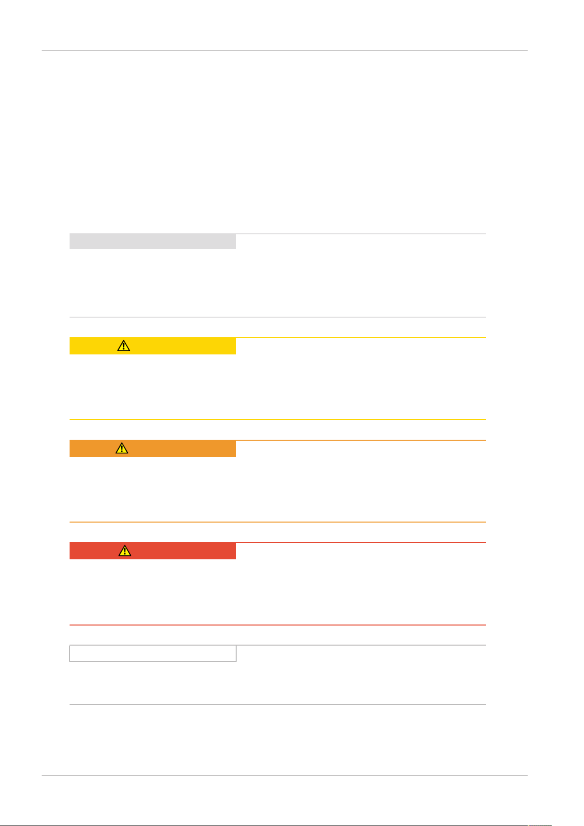
2.5.1 Use of symbols
Safety instructions are identified with the following symbols. They indicate special risks when
handling the product and are accompanied by relevant signal words that identify the extent of
the risk. In addition useful tips and recommendations for efficient and faultless operation are
specially highlighted.
ATTENTION!
Please note
means that material damage may occur
▪ if the stated precautionary measures are not complied with.
CAUTION!
Caution
with a warning triangle means that slight personal injury may occur,
▪ if the stated precautionary measures are not complied with.
WARNING!
Warning
with a warning triangle means that a considerable danger to life may arise
▪ if the stated precautionary measures are not complied with.
DANGER!
Danger
with a warning triangle means that a considerable danger to life will arise
▪ if the stated precautionary measures are not complied with.
Information
Information refers to important information about the product or serves to emphasize a section
in the documentation to which the reader should pay special attention.

STOBER 2 | User information
07/2016 | ID 442728.00
9
2.5.2 Text display
Certain text elements are featured as follows to facilitate orientation.
Text Words or expressions with a special meaning
Text Window names, dialog names, page names or buttons,
composed proper nouns, functions cited by the interface
Text Assigned entry
<Text> User-defined entry
TEXT
Displays (status, messages, warnings, faults) of the status
information cited by the interface
Keyboard shortcuts or command sequences or paths are represented as follows.
[CTRL], [CTRL] + [S]
Key, shortcut
Table > Insert table Navigation to menus/submenus (path specification)
2.6 Symbols and test symbols
The following symbols and test symbols are used in this document.
Grounding symbol
according to IEC 60417-5019 (DB:2002-10).
Lead-free identifier RoHS
according to RoHS directive 2011-65-EU.
CE mark
Manufacturer's self declaration: The product meets the
requirements of EU directives.
UL-test mark
This product is listed by UL for the USA and Canada.
Representative samples of this product have been evaluated by
UL and meet the requirements of applicable standards.
UL test marks for recognized components
This component or material is recognized by UL. Representative
samples of this product have been evaluated by UL and meet
applicable requirements.

2 | User information STOBER
10
07/2016 | ID 442728.00
2.7 Trademarks
The following names that are used in conjunction with the device, its optional equipment and its
accessories are trademarks or registered trademarks of other companies:
EnDat®EnDat® and the EnDat® logo are registered trademarks of Dr.
Johannes Heidenhain GmbH, Traunreut, Germany.
EtherCAT®,
Safety over EtherCAT®,
TwinCAT®
EtherCAT®, Safety over EtherCAT® and TwinCAT® are registered
trademarks and patented technologies that are licensed by
Beckhoff Automation GmbH, Verl, Germany.
HIPERFACE®HIPERFACE® and the HIPERFACE DSL® logo are registered
trademarks of SICK STEGMANN GmbH, Donaueschingen,
Germany.
All other trademarks that are not listed here are the property of their respective owners.
Products that are registered as trademarks are not specially indicated in this documentation.
Existing property rights (patents, trademarks, protection of utility models) are to be observed.

STOBER 3 | General safety instructions
07/2016 | ID 442728.00
11
3 General safety instructions
The product described in this documentation can present risks. For this reason, always comply
with the safety information, technical rules and regulations listed.
3.1 Directives and Standards
The product specified in this documentation was developed and built according to the state-of-
the-art. However there are residual risks that can be prevented by complying with the described
warning and safety instructions.
The product complies with the following European directives and standards:
§Machine Directive 2006/42/EC
§Low Voltage Directive 2014/35/EU
§EMC Directive 2014/30/EU
§EN 61326-3-1:2008
§EN 61800-3:2004 and A1:2012
§EN 61800-5-1:2007
§EN 61800-5-2:2007
§EN 50178:1997
3.2 Qualified personnel
To be able to perform the tasks described in this documentation, the persons authorized for
them must have the appropriate professional qualification and be able to assess the risks and
residual risks when handling the products. For this reason, all work on the products as well as
their operation and disposal may only be performed by professionally qualified personnel.
Qualified personal are persons who have acquired the authorization to perform these activities
either through training to become a specialist and/or instruction by specialists.
In addition the valid regulations, legal requirements, applicable basic rules, this documentation
as well as the safety instructions included in it must be carefully read, understood and observed.
3.3 Intended use
As defined by DIN EN 50178, the SI6 drive controller and the PS6 supply module are electrical
devices operating as power electronics to control the flow of energy in high voltage systems.
The SI6 drive controller is intended for the operation of synchronous servo motors and
asynchronous motors.
The connection of other electronic loads constitutes improper use!
The PS6 supply module is intended for the supply of one or more drive controllers. Only drive
controllers of the 6th generation of STOBER drive controllers may be connected to the PS6.

3 | General safety instructions STOBER
12
07/2016 | ID 442728.00
3.4 Transport and storage
Inspect the delivery for any transport damage immediately after you receive it. Notify the
transport company of any damage immediately. Do not place the product in operation if it is
damaged.
To ensure the faultless and safe operation of the products, they must be professionally set up,
mounted, operated and maintained. If you have to transport or store the products, you must
protect them from mechanical impact and vibrations as well as observe the recommended
transport and storage conditions in the technical data.
Store the products in a dry and dust-free room if you do not install them immediately.
Form drive controllers in storage annually or before startup (see section Bearing [}54]).
3.5 Operational environment and operation
The products are subject to sales restrictions in accordance with IEC 61800-3.
The products are not designed for use in a public low frequency network that supplies
residential areas. High-frequency interference can be expected if the products are used in a
network of this type.
The products are designed exclusively for operation in TN networks.
The products are intended exclusively for installation in control cabinets with at least protection
class IP54.
Always operate the products within the limits specified by the technical data.
The following applications are prohibited:
§Use in areas subject to explosion hazard
§Use in environments with harmful substances as specified by EN 60721, for example oils,
acids, gases, vapors, dust and radiation
Implementation of the following applications is only permitted after approval from STOBER:
§Use in non-stationary applications
3.6 Working on the machine
Apply the 5 safety rules in the order stated before performing any work on the machine:
§Disconnect (also ensure that the auxiliary circuits are disconnected).
§Protect against being turned on again.
§Check that voltage is not present.
§Ground and short circuit.
§Cover adjacent live parts.
Information
Note that the you can only determine that no voltage is present when the discharge time has
elapsed. The discharge time depends on the self-discharging of the drive controller and, if
necessary, the fast discharge. You can find the discharge time in the common technical data.

STOBER 3 | General safety instructions
07/2016 | ID 442728.00
13
3.7 Disposal
Observe the current national and regional regulations when disposing of the product! Dispose of
the individual product parts depending on their properties, e.g. as:
§Electronic waste (circuit boards)
§Plastic
§Sheet metal
§Copper
§Aluminum
§Battery

4 | System configuration STOBER
14
07/2016 | ID 442728.00
4 System configuration
The multi-axis drive system consists of at least one PS6 supply module and one SI6 drive
controller. For the energy supply of the existing drive controllers in the group, you need suitable
Quick DC-Link modules for the DC link connection for each supply module and for each drive
controller.
For the connection to a controller, we recommend the EtherCAT fieldbus as well as an
application with CiA 402 interface. You can place the drive controller in operation with the
DriveControlSuite software.
The drive controller offers the STO safety function according to EN 61800-5-2 as an option. For
the connection to a higher-level safety circuit, different interfaces are available.
The following graphic explains the principle system configuration.
Field bus
Motion controller MC6
1 x supply module PS6,
3 x drive controller SI6
Actuator / sensor level,
electromechanics
Field level Controller level
Synchronous servo motors,
asynchronous motors
Command level
Safety
Commissioning
Fig.1: System overview for the multi-axis drive system with SI6 and PS6

STOBER 4 | System configuration
07/2016 | ID 442728.00
15
4.1 Hardware components
Below you will gain an overview of the available hardware components.
4.1.1 Supply module
The PS6 supply module is available in two sizes. The type specifications used in this manual
refer to the nameplate that is placed on the side of the supply module.
4.1.1.1 Nameplate
Fig.2: Nameplate PS6A24

4 | System configuration STOBER
16
07/2016 | ID 442728.00
Designation Value in the example Meaning
Type PS6A24 Device type according to type designation
ID no. 56650 Identification number
HW 003 HD Production information
Date 1602 Production week in format YYWW, in the
example shown here year 2016, week 2
S/N 9001042 Serial number
Input voltage 3 × 400VAC
UL: 3 × 480VAC
Input voltage
Input current 3 × 25.0A Input current
Output data 560 VDC
10.0 kW
Output voltage
Nominal output
Protection class IP20 Protection class
Tab. 1: Meaning of the specifications on the PS6 nameplate
Information
UL and cUL (CSA-UL) certified devices with corresponding test mark meet the requirements of
standards UL 508C and UL 840.
4.1.1.2 Type designation
PS 6 A 2 4
Tab. 2: Example code for the PS6 type designation
Code Designation Design
PS Series PowerSupply
6Generation 6. Generation
AVersion
2–3 Size
4Power output stage
Tab. 3: Meaning of the PS6 example code

STOBER 4 | System configuration
07/2016 | ID 442728.00
17
4.1.1.3 Sizes
Type ID no. Size
PS6A24 56650 Size 2
PS6A34 56651 Size 3
Tab. 4: Available PS6 types and sizes
Fig.3: PS6 in sizes 2 and 3
Note that the basic device is delivered without terminals. Suitable terminal strips are available
separately for each size.
Terminal strip for supply module
The following versions are available:
ID no. 138660
Terminal strip for PS6A24.
ID no. 138661
Terminal strip for PS6A34.

4 | System configuration STOBER
18
07/2016 | ID 442728.00
4.1.2 Drive controller
The SI6 drive controller is available in three sizes as a single or double axis controller. In
additional different safety options are available. The type specifications used in this manual
refer to the nameplate that is placed on the side of the drive controller.
4.1.2.1 Nameplate
Fig.4: Nameplate SI6A061Z

STOBER 4 | System configuration
07/2016 | ID 442728.00
19
Designation Value in the example Meaning
Type SI6A061Z Device type according to type designation
ID no. 56645 Identification number of the basic device
HW 003 HD Production information
Date 1602 Production week in format YYWW, in the
example shown here year 2016, week 2
S/N 9001043 Serial number
Input voltage 560VDC Input voltage
Output data 0...460 VAC
0...700 Hz
@4kHz: 3 × 5.0A
@8kHz: 3 × 4.5A
Output voltage
Output frequency
Output current for 4 kHz clock frequency
Output current for 8 kHz clock frequency
Protection class IP20 Protection class
Tab. 5: Meaning of the specifications on the SI6 nameplate
Information
UL and cUL (CSA-UL) certified devices with corresponding test mark meet the requirements of
standards UL 508C and UL 840.
4.1.2.2 Type designation
SI 6 A 0 6 1 Z
Tab. 6: Example code for the SI6 type designation
Code Designation Design
SI Series ServoInverter
6Generation 6. Generation
AVersion
0–2 Size
6Power output stage Power output stage within the size
1
2
Axis controller Single axis controller
Double axis controller
Z
R
Y
Safety technology SZ6: without safety technology
SR6: STO via terminals
SY6: STO via FSoE
Tab. 7: Meaning of the SI6 example code

4 | System configuration STOBER
20
07/2016 | ID 442728.00
4.1.2.3 Sizes
Type ID no. Size
SI6A061 56645 Size 0
SI6A062 56646 Size 0
SI6A161 56647 Size 1
SI6A162 56648 Size 1
SI6A261 56649 Size 2
Tab. 8: Available SI6 types and sizes
Fig.5: SI6 in sizes 0, 1 and 2
Note that the basic device is delivered without terminals. Suitable terminal strips are available
separately for each size.
This manual suits for next models
8
Table of contents
Popular Industrial Electrical manuals by other brands

Murata
Murata GRM1887U1H272JA01 Series Reference sheet

Murata
Murata GRM188C71A475ME11 Series Reference sheet

Magnetek
Magnetek ELECTROBAR FS instruction manual

Bredenoord
Bredenoord ESaver III Operation manual

Murata
Murata GRT31CR61C335ME01 Series Reference sheet

Spectrum Industries
Spectrum Industries 55114 Assembly instructions


Murata
Murata GRM0225C1E3R4CA03 Series Reference sheet

Festo
Festo FEC Standard Brief description

hager
hager univers IP44 Mounting instructions

Murata
Murata GRM152C80G224KE19 Series Reference sheet

Phoenix Contact
Phoenix Contact EV-T2GBIE-1ACDC-20A125A Series Safety, installation and operation notes

Acclaim Lighting
Acclaim Lighting AJBOX1 user guide