Smith Manufacturing FS200 User manual

CUTTERS / REMOVERS / PARTS / SUPPORT
SMITH MANUFACTURING
1-800-653-9311
www.SmithMfg.com
Phone: 954-941-9744 • Fax: 954-545-0348
FS200™/FS209™
Compact Remover
User Guide & Parts List Manual

SMITH Manufacturing 1-954-941-9744 www.SmithMfg.com
21/2008
FS200/FS209
INDEX
Page Contents
2 Index
3 Introduction
4 Safety Guidelines
5 Your FS200 Surface Preparator
6 Cutter Drum Assembly
7 Machine Start-Up
8 Transporting & Substrate Removal
9 Storage & Ordering
10 Troubleshooting
11-12 Parts List
13-14 Optional Electric Motor
15 Drum Assembly
16 Carbide Prep-It™ Strip Drum Assembly
17-18 Cutter Set-Up
19 Recommended Spares List
20-21 Edger Assembly
22 Maintenance Log
23 Limited Equipment Warranty Info
24 Warranty Activation

SMITH Manufacturing 1-954-941-9744 www.SmithMfg.com
1/2008 3
FS200/FS209
INTRODUCTION
Congratulations on purchasing the FS200™/FS209™ Compact Remover from SMITH Mfg. Company.
The FS200™ uses a 5.5 Honda Engine, while the FS209™ uses a 9 HP Honda Engine.
Your machine will:
•Cleansurfacesimpactedbygrease,oil,plastics,tars,resins,tileadhesives,iceandmore
•Planeormillasphaltandconcretesurfaces
•Removehighspotsincurbsandgutters
•Eliminatetrip-hazardsonconcretesidewalks
•Millareasforrumblestrips
•Cleanoutcracksandjoints
•Createanti-slippatternsinwalkwaysandbarns
•Preparesurfacesfornewcoatingapplications
•Permanentlyremoveallroadandsurfacecoatingstoinclude:
epoxy,urethane,thermoplastic,paint,glue-backedtapesandmore...
•Groove-inlayasphaltforstriping
•Preparesurfacepriorto“HotTape”applications
BEFORE START-UP, READ THIS...
Please read all operating instructions, including the provided engine manual and be completely fa-
miliar with your equipment before operating. When in doubt, please contact SMITH Manufacturing or
your local dealer for operation details.
ThisOwner’sManualwillguideyouthroughtheremovalprocess,fromstarttonish,andshowyou
how to care for your machine.
Remember to activate your warranty - refer to
“Pre-Operation Inspection and Warranty Activation” page
at the end of this manual.
UNCRATING YOUR EQUIPMENT
Whenyouuncrateyourequipment,makecertainthatthemachinehasnotbeendamagedand
that all fasteners and guards are properly tightened.
Your machine may not have been shipped assembled with cutters and other accessories.
Assembly may be required.
Remember:Onlyauthorized,experiencedandproperly
trained personnel should operate this equipment.
Operating personnel should practice safety at all times
and wear protective gear (breathing apparatus, gloves,
goggles, safety vests, ear plugs, steel-toe shoes, etc.)
Model #: Serial #:

SMITH Manufacturing 1-800-653-9311 www.SmithMfg.com
41/2008
FS200/FS209
SAFETY GUIDELINES
Incorrect use of the surface planer can result in
property damage, personal injury, or death.
Be sure to read and follow all directions and
precautions as outlined in this manual.
Operation •Getacquaintedwiththecontrols(pg.3)
•Alwayswearprotectiveequipment,includingearprotection,breathing
apparatus, steel-toed shoes, and goggles.
•Neverwearbaggyorloosettingclothingthatcanbecaughtoncontrolsor
moving parts.
•Thesurfacepreparatorcanemityingparticlesanddebrisduringoperation.
Neveroperatethemachinenearbystanders,animalsorchildren.
•Donotoperatethemachineinanexplosiveatmosphere,nearcombustible
materials, or when gas fumes may not be properly dispersed.
•Neverleavethemachineunattendedwhenrunning.
Operator must hold onto the handle with two hands when the cutter drum is
engaged.
•Avoidcontactwiththemuferwhentheengineishot,asitmaycaisesevere
burns.
•Whenusingavacuumsystem,avoidhosecontactwiththemufer.
•Stopenginebeforerefuelingtank.Donotallowfueltocomeincontactwiththe
hot parts of the engine or spill on the ground.
•Donotsmokeorhandleopenrenearthismachine.
•Gastanklidmustclosetightly.Shutofffuelcockwhenshuttingoffengine.
Whentransportingthemachine,thefueltankmustbecompletelydrained.
Service •Makesurethattheengineisshutdownandthesparkplugisdisconnected
before servicing.
•Repairanyfuelleaksimmediatelyandremoveaccumulateddustfrequently
fromtheairltersystem.
•Cleanthemachineregularly.
•Removesideplatescrewsandcheckforwear.
Daily Checklist •Checkuidlevels
•Ensurethatallguardsareinplacebeforethemachineisoperated,since
rotatingandmovingpartswillcauseinjuryuponcontact.
•CheckandReplace(asneeded):
•Cutters •Bearings
•Shafts •DriveShaft
•DustFlap •Wheels
•Checkthatallfastenersaresecure
•CheckthatallControlsandSafetyDevicesarefuntioningproperly

SMITH Manufacturing 1-954-941-9744 www.SmithMfg.com
1/2008 5
FS200/FS209
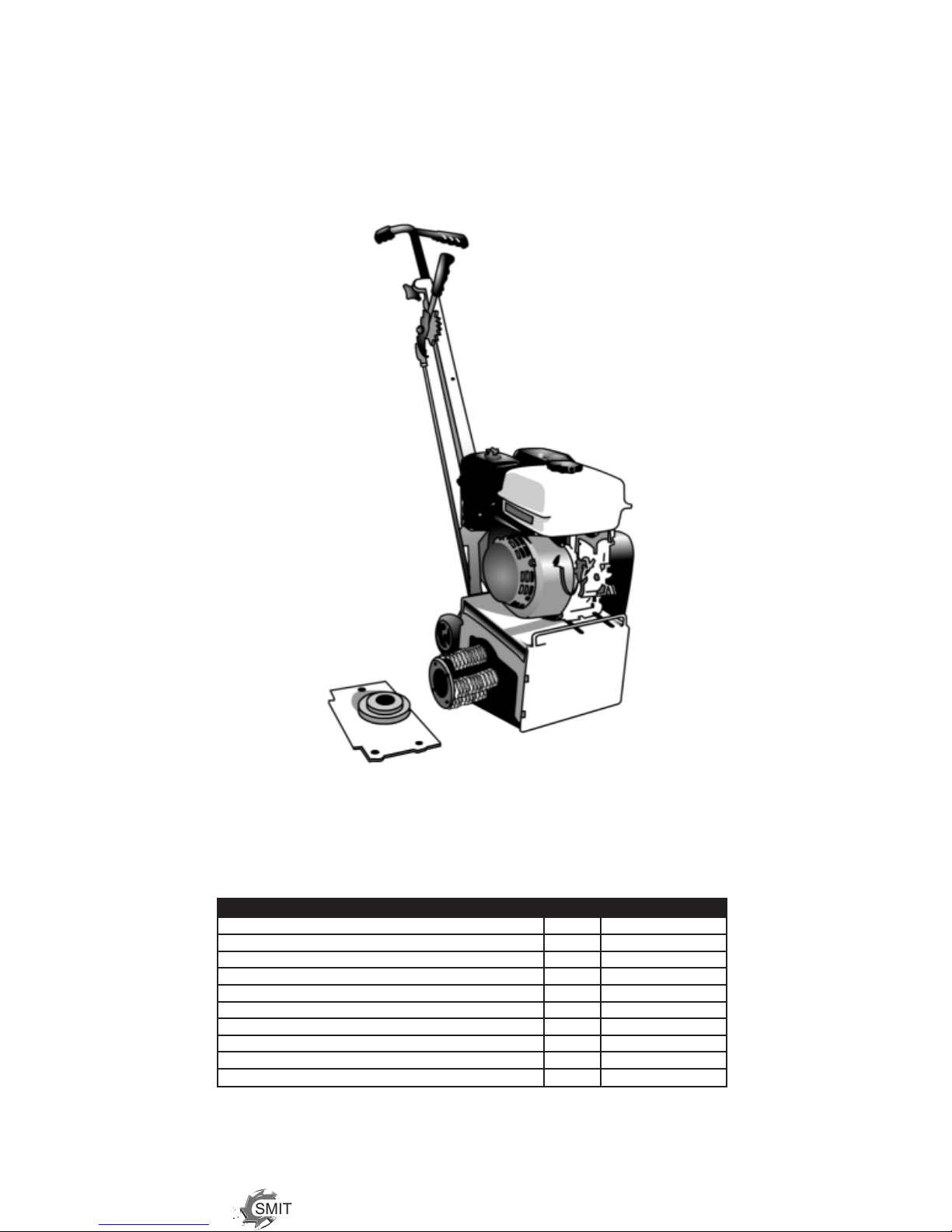
YOUR FS200™ SURFACE PREPARATOR
PleasetakeamomenttofamiliarizeyourselfwiththeFS200™’s
controls, as well as some of the features of your new machine.
For Assembly diagrams and parts numbers, please refer to pages 9-16.
Read the engine manual before preparing the engine for starting.
(c/w CF2515™ Ultra-Premium Carbide cutters - depicted)
AdjustableHandlebar
Throttle
GasTank
OilDipstick
Removalble Side Plate
Drum Assembly
Depth Control Lever
Engine Cleaner

SMITH Manufacturing 1-800-653-9311 www.SmithMfg.com
61/2008
FS200/FS209
CUTTER DRUM ASSEMBLY
CARBIDE or STEEL?
Whenconguringyourcutterdrumforremoval,oneofthemost
importantquestionstoaskis:“WhichcuttertypedoIuse,carbideorsteel?”
Tungstencarbidewillproduceasmoothersurfacenishifsetupproperly:
without spacers, in an offset pattern. Professionals use
SMITH’s Ultra-Premium tungsten carbide cutters to save time and money.
NOTE: OnlySMITHBrandUltra-PremiumTungstencarbideisthemost
cost-effective cutting tool and lasts up to 25x longer than conventional cutters
while removing 5x faster on asphalt or concrete.
There are many types of cutters that you can use on this machine
(RefertoourCutterDatasheetforspecicsizesandorderinginformation):
1 Beamsteelcuttersfor
HS1013™ gentle scarifying.
2Star steel cutters for light
to medium scarifying.
HS1003™
Tungstencarbidespikedcutterstoremove
3coatings, as well as clean, plane, mill, scarify,
CF2515™ CF2516™ roughen, smooth, groove, grind, eradicate or
remove on concrete or asphalt.
4Special carbide scrapers designed for asphalt-removing Hot Tapes,
CF2519™ CF2535™ preformtapes,thermoplasticsorthicklmcoatings.
5 Angleddirectionalsteelcutterforremovingtoughnon-skidcoatings.
HS1011™
CUTTER SET-UP
Remove one retaining plate(ILL #3, pg. 11) and load the cutters and spacers on each shaft using the
cutter charts (pg. 12-13) as a guide.
Makecertainthatthedrumisbalanced.Anunbalaneddrumisunsafeandmaycauseexessive
vibration,damagedbearings,brokenshaftsandreducedcutterlife.
TIP:Loadcutterswithoutspacersforthebestnish.
Offsetoraligncarbide-spikedcutters(#3-5,above)forgrooving,
surface leveling, or removing. And ALWAYS load the special
milling cutters in the same direction, with the carbide adge cutting
rst,andspacedwithatleastonespacer(seepage13fordetails).
Thereshouldbe1/8”-1/4”playoneachsectionofcuttershaft.

SMITH Manufacturing 1-954-941-9744 www.SmithMfg.com
1/2008 7
FS200/FS209
MACHINE START-UP
Do not start machine while drum is in contact with
the ground. Doing so can cause the operator to lose control of
themachine,resultinginpropertydamageand/orpersonalinjury.
1)Openthefuelcockonthegastankandthenplacethethrottleleveratthe
“FastIdle”position.
2)Starttheengine,openchokeslightlytopreventooding.
3) Move throttle control to open or run position when engine is warmed up.
4)Increasethrottletomaximumoperatingposition(approx.1800RPM)andclosechoke.
Beforesubstrateremoval,testrunthedrumwithcuttersnottouchingthesurface.Ifthereis
exessivevibration,youneedtore-balancethecutterset-up,checkbearingcondition,and/or
makesurethattheengineside-plateissecured.
IF THE ENGINE DOES NOT START...
1)CheckEngineforpropergasandoillevels(refertoEnginemanual)
2)Checksparkplug.Makesurethesocketareasarecleanandclearofdebris,andthatthe
proper gap is set. (Replace if needed).
3)TurntheOn/Offswitch,onthefrontoftheEngine,to“On”.
4)Enginemayhavetiltedbackwards.Ifso,allowoiltodrainafterremovingsparkplug.
*Engine repair and engine warranty issues are handled directly by
your local Honda engine service center.
Warning: Should you desire to tilt the machine, always tilt forward.
Tiltingthemachinebackwardsatanytimewilloodthesparkplug
with oil and may cause damage to your engine!
RIGHT WRONG

SMITH Manufacturing 1-800-653-9311 www.SmithMfg.com
81/2008
FS200/FS209
Transporting
Duringtransport,loadingandunloadingofthescarierbymeansofliftingdevices,useappropriate
slings,orhooksontheliftingpoints,providedforthispurpose.
Theload-carryingcapacityhastobesufcientandsecuresuchthattheycannotturnover.Make
sure that no one is endangered by the machine turning over. When being transported on vehicles,
precautionshavetobetakenthatthescariersaresecuredanddonotmove.
SUBSTRATE REMOVAL
AdjusttheheightofthecutterdrumwiththeDepthControlLever.Setthedepthofcuttoallow
the cutters to go through only the materials to be removed.
Makecertainthethedrumispositionedtowhereonlythecuttersstrikethesurface,andthatthedrum
assembly never comes into contact with the substrate.
The cutter tips alone should strike the surface(1/8”to1/4”maximumdepthperremovalpasson
new cutters).
The drum will not withstand substrate contact. Contacting the removal surface too deeply will
cause premature wear to cutters, shafts, drum and other components! TIP: The correct depth
setting is indicated by relatively little machine vibration.
Too much downward pressure only has negative results. Try to remove materials in several
passes rather than one, deep pass. Several tests will show the best, most appropriate cutter impact.
Useaforward,backwardand/orcircularpatterntoachieveyourdesirednish.
NOTE: Only use a forward motion when using the CM2519™ or CM2535™ carbide scraping cutters.
TIP: Position the machine over the surface in many direrctions
to help create desirable surface patterns. After several hours of
practice, the operator will become comfortable and should be able
to remove materials faster with enhanced results.
Whenthejobiscompleted,ortheoperatorwantstoceasework,stoptheenginebyrstlifting
the drum above the substrate using the Depth Control lever. Stop the machine only at the engine.
Thenclosethefuelcocktoshutoffthefuelsupply.
The drum assembly must be removed daily and inspected for drum wear, hole elongation and
possible weld seperation. Replace the cutter shafts prior to any drum wear. If the drum’s center
holes are elongated, order another SMITH cutter drum.
Refer to pg. 8 for troubleshooting problems.

SMITH Manufacturing 1-954-941-9744 www.SmithMfg.com
1/2008 9
FS200/FS209
STORAGE
•Shutofffuelvalveandsiphonallexcessfuel.
•Startengineandrununtilitstalls.
•Removesparkplugandpourtwoouncesofmotoroilinto
cylinderandslowlycranktheenginetodistributeoilto
prevent rust during storage.
•Replacesparkplugandstoremachineuprightinacool,
dry, and well-ventilated area.
Maintenance Checks
Accordingtotheconditionsandfrequencyofuse,scariers
havetobecheckedforsafeoperationatleastonceayearby
skilledtechnicians,suchasthosefoundatthemanufacturer’s
service depots, and have to be repaired if necessary.
ORDERING
When ordering please specify the model and serial number
of the machine. In addition, give a part number, description,
and quantity as listed on your parts list.
If you have any questions about the operation of your machine
orwouldliketoorderreplacementparts,contactyourdealeror
SMITH Manufacturing.
Contact SMITH at 1-800-653-9311 (954-941-9744) for information,
or visit our website at www.smithmfg.com.
To ensure product safety and reliability, and to maintain
your warranty, always use genuine replacement cutters
and parts from SMITH MFG when making repairs to
equipment.

SMITH Manufacturing 1-800-653-9311 www.SmithMfg.com
10 1/2008
FS200/FS209
TROUBLESHOOTING
If engine does not start, read pg. 5
Problem Possible Reason(s)/Solution(s)
Cutters wearing unevenly/prematurely 1Drum is too low, 2Incorrect set-up,
3Material build-up,
4Cutters too tightly loaded, and/or
5Wrongcuttersforthejob.
Cuttershaftbreakageprematurely 1Drum too low, 2End plates worn,
3Shafts worn, and/or
4Wrong cutter set-up.
Drumwearingprematurelyorcracking 1Drum hitting ground, and/or
2Shafts not replaced in time.
Excess vibration 1Bearingfailure,2Hex bushing worn,
3Drive shaft worn,
4Improper cutter set-up,
5Drum contacting ground, and/or
6Wheels worn out.
Machinejumpserratically 1Drum hitting ground, 2RPM is too low,
and/or 3Surface is severely uneven.
“V”beltwearprematurely 1Pulley is misaligned, 2Wrong belt,
and/or 3Drum is contacting surface.
DepthControlLeversettoolow AdjustHeightofLever:
1)OpenSpringx(#9B,pg.9),usingascrewdriver
to gently pry it open, if needed.
2) Disengage Clevis from Handle Assembly by pulling
straight out, away from handle.
3)ToAdjustHeight:
TurnLocknut(#9C,pg.9),andmovetodesired
position.
4) Reattach Clevis and Snap outer piece into place.
*NOTE:Forevengreateradjustments,repeat
procedure for Clevis at bottom of Handle Assembly
Uneven Cutting 1Cutting too deeply, and/or
2Rearwheelforkisbent.
For any other problems or questions, please contact your local representative
or SMITH Mfg today at 800-653-9311 or (954) 941-9744.
*Engine repair and engine warranty issues are handled
directly by your local engine service center.

SMITH Manufacturing 1-954-941-9744 www.SmithMfg.com
1/2008 11
FS200/FS209
ILL # Description Part Number Qty.
1 Housing 511.1063.2 1
2 DustFlapRetentionBar 511.1021.240 1
3 Dust Flap 511.1022.240 1
4 Hex Screw M10 x 20 998.1009.25 10
5 Spring Washer 991.1020.10 10
6 Plain Washer M10 991.1002.10 3
7 Penny Washer 991.1091.10 3
8 Sideplate Assembly (w/bearings) 511.1055A 1
9 AdjustmentRodAssembly 516.1000A 1
A ClevisM10Springx 516.1004 1
B ClevisSpringM10Springx 516.1006 1
C LockNut 990.1020.10 1
D AdjustmentRod 513.1000 1
E LockNut 990.1020.12 1
F ClevisSpringM12Springx 516.1007 1
G ClevisM12Springx 516.1005 1
10 AdjustableHandleAssembly 500.2000.9 1
A Grip 510.1016.2 1
11 HanldeBar 510.1020.1 1
12 Rubber Handle Grip 510.1016.1 2
13 Plastic Knob 907.1001.1 1
14 Handle 510.1000 1
15 VacuumPortCap 904.1000.3 1
16 BackWheelAssembly 515.1007A 1
A Cotter Pin 989.3002.20 2
B PlainWasherM14 991.1001.14 4
C Wheel 905.1000.1 2
D Wheel Carrier 515.1007 1
ILL # Description Part Number Qty.
16E HexHeadBolt 506.1008 2
F Plain Washer M12 991.1001.12 4
G NylonInsertNut 506.1009 2
17 Honda Engine w/oil alert
5.5 HP 15026 1
9 HP 15027 1
18 BeltGuardBracketAssembly 511.1060A 1
A BeltGuardBracket 511.1060 1
B HexScrewM8x30 998.1008.30 2
C Plain Washer M8 991.1002.8 4
D NylonInsertNutM8 990.1001.9 2
E Hex Screw M10 x 20 998.1009.25 2
F Spring Washer 991.1020.10 2
G Plain Washer M10 991.1002.10 2
19 BeltGuard
FS200 505.1001 1
FS209 505.1001.9 1
20 Engine Mounting Hardware 501.1011.4A 2
A “U”Bolts 501.1011.4 1
B PlainWasherM8 991.1002.8 2
C NylonInsertNutM8 990.1001.8 2
21 Front Wheel Assembly 530.1006A 1
A Front Wheel 530.1006 1
B HexHeadBolt 990.1009.75 1
C Plain Washer M10 991.1001.10 1
D FrontWheelBushing 530.1005.10 2
E NylonInsertNutM10 990.1001.10 1
22 Serial Plate 80001 1
23 Drive Screw 10129 2
Parts List
SMITH Manufacturing 1-800-653-9311 www.SmithMfg.com
12 1/2008
FS200/FS209
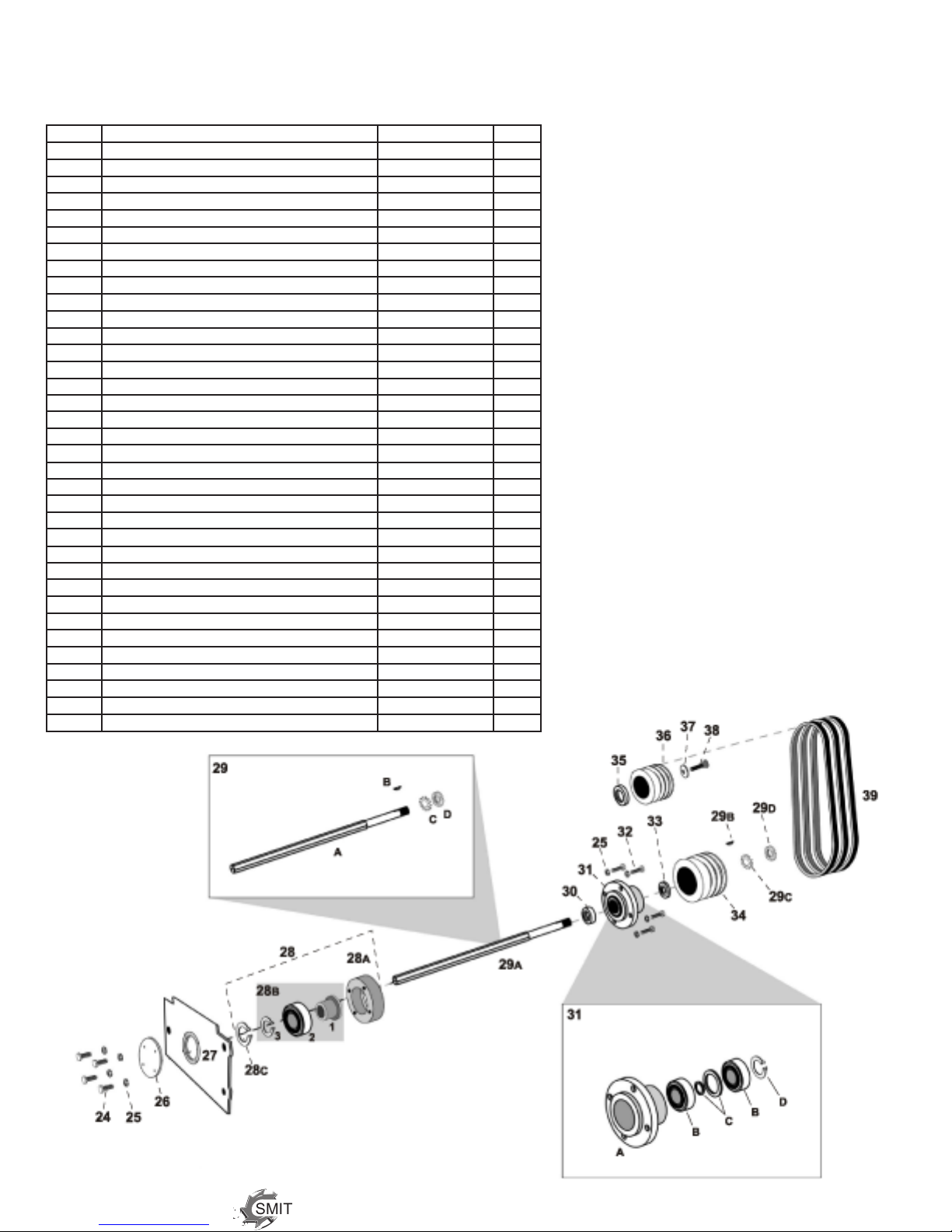
ILL # Description Part Number Qty.
24 Screw M8 x 20 998.1020.20 4
25 Spring Washer M8 991.1020.8 8
26 BearingCover 511.1020 1
27 Side Plate 511.1055.2 1
28 DriveBearingAssembly,Outer 979.1000A 1
A BearingFlange 512.1002 1
B HexBearingAssembly 514.1000A 1
1HexBushing 514.1000 1
2BallBearing(6006-2RS) 979.1000.18 1
3 External Circlip, 30 mm 977.1010.30 1
C Internal Circlip, 55 mm 977.1000.55 1
29 Shaft Assembly 513.1000A 1
A Hex Shaft 513.1000.1 1
B WoodruffKey 979.9021 1
C Tabbed Washer 979.1021.1 1
D LockNut 979.9020.1 1
30 Shaft Spacer 109.1033.7 1
31 DriveBearingAssembly,Inner 512.1000A 1
A BearingHousing 512.1000 1
B Bearing(6303-2RS) 979.1000.12 2
C Setof2BearingSpacers,Large&Small 109.1033.11 1
D Internal Circlip, 47 mm 977.1010.47 1
32 Cap Screw M8 x 12 997.1008.12 4
33 Pulley Spacer 506.1007 1
34 Drive Pulley w/set Screw, Lower 518.1006 1
35 Engine Spacer 302.1005.9 1
36 Engine Pulley w/set Screw, Upper 1
for 5.5 HP (FS200) 518.1005 1
for 9 HP (FS209) 518.1009 1
37 Pulley Retaining Washer 302.1008 1
38 Bolt5/16-24x1” 998.1035.16 1
39 Belts,Vfor5.5HP 3
SPZ 710 (for early gas models) 967.1010.710 3
SPZ 722 (for later models) 967.1010.722 3
for 9 HP (SPZ 750) 961.1010.750 3
Parts List

SMITH Manufacturing 1-954-941-9744 www.SmithMfg.com
1/2008 13
FS200/FS209
Optional ELECTRIC MOTOR
ID # PART # QTY. DESCRIPTION
150 ES-200-698 1 ElectricMotor,230V
151 ES-200-1209 1 Starting Condender
152 ES-200.1210 1 Operating Condenser
153 ES-200-12101 2 Holder for Condenser
154 ES-200-12102 1 TerminalBoxCover
155 ES-20-12111 1 Fan Cover
156 ES-200-12113 1 Fan
157 ES-200-1211 1 Relay
158 ES-200-7616 4 Hexagon Screw
159 ES-200-7633 4 Conical Spring Washer
160 ES-200-762 4 Spacer
161 NotUsed
162 ES-200-12103 1 TerminalBox
163 ES-200-902 1 Key for Electric Motor
164 ES-2009051 1 Spacer for Electric Motor USA
165 ES-200905 1 Driving Disc Electric Motor USA
166 NotUsed
167 NotUsed
168 ES-200-907 1 LockingRing
169 ES-200-913 1 Spring Washer
170 ES-200-914 1 Hexagon Screw
171 ES-200-740 2 Plate for Electric Motor
172 ES-200-850 2 Counterplate Electric Motor
173 ES-200-9021 1 Key for Gaoline Motor
174 ES-200-903 1 DrivingDiscB.-MotorHONDA
175 ES-200-9031 1 SpacerB.-MotorHONDA
176 ES-200-904 1 DrivingDiscB.-MotorB&S
177 ES-200-9041 1 SpacerB.-MotorB&S
178 ES-200-7615 4 Hexagon Screw
179 ES-200-7001 1 Air Filter
180 ES-200-700 1 Gasoline Motor Honda
181 ES-200-760 2 CounterplateB.-Motor
SMITH Manufacturing 1-800-653-9311 www.SmithMfg.com
14 1/2008
FS200/FS209
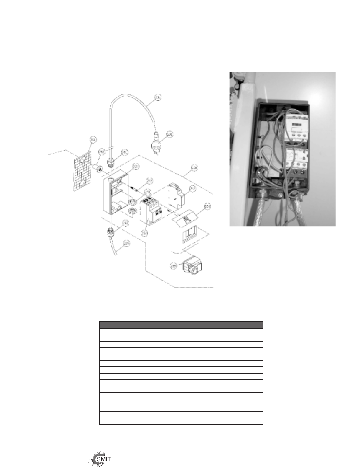
Optional ELECTRIC MOTOR
ID # PART # QTY. DESCRIPTION
230 ES-200-1066 1 Switch Complete
231 ES-200-1047 1 Lower Switch Housing
232 ES-200-1060 1 CircuitBreaker
233 ES-200-1052 1 Undervoltage Release
234 ES-200-10471 1 Upper Switch Housing
235 ES-200-1048 1 Emergency Stop Switch
236 ES-200-1151 1 Plug
237 NotUsed
238 ES-200-1101 1 Lead Wire
239 ES-200-1102 1 Connection Cable
240 ES-200-108 2 Conduit Gland
241 ES-200-1081 2 LockingNut
242 ES-200-10421 2 Allen Screw
243 ES-200-1055 2 Shock-Reducer
244 ES-200-1056 1 Rubber Plate

SMITH Manufacturing 1-954-941-9744 www.SmithMfg.com
1/2008 15
FS200/FS209
Drum Assembly
ILL# P/N Oty. Description
1 504.4021.12 1 Drum Assembly (includes #2 - #5)
2 S-507.1001 4 Cutter Shaft (12 mm)
3 504.2035 2 Retaining Plate
4 998.1005 8 LockNut
5 990.1001 8 Cap, Screw
6 CF2515™ $ 5SpikeTungstenCarbideCutter
CF2516™ $ 6SpikeTungstenCarbideCutter
CF2535™ $ 5 Edge Carbide Scraping Cutter
CF2519™ $ 7 Edge Carbide, Angled Scraping Cutter
HS1003™ $ Steel Star Cutter
HS1011™ $ Steel Cutter, Angled
HS1013™ $ SteelBeamCutter
122230™ $ Spacer,1/2”
$ Refer to cutter set up on pages 12-13

SMITH Manufacturing 1-800-653-9311 www.SmithMfg.com
16 1/2008
FS200/FS209
Carbide Prep-It™ Strip Drum Assembly
P/N: 8200.02
Therubber“PrepStrip™”drumcomespresetwithstripsinstalledina
staggered pattern to ensure contact with the surface being stripped.
The following guidelines will show you how to get the longest life out of
your drum:
•Afterinstallation,lowerthedrumslowlytobegincontactingthe
surface.
•Loweronlyenoughtocontactthesurfaceanddothejob.
•Excesspressureonlyincreaseswear,notcuttingspeed.
•Runengineatmoderatespeeds.
•Slowspeedswillnotprovideagoodnish.
•Fastspeedsacceleratewearonallmachinepartsaswell
as the stripping bits.
•Afterextendedusage,examinethecuttingtips.Ifworn
excessively, remove the drum and replace all 7 strips.
Replacing Rubber Prep-It™ Strips
The rubber strips are set up at the factory in precut lengths. When worn, all 7 strips must be replaced
to ensure that equal contact is made with the surface.
Tools needed: Wrenches, Screw Driver, Pliers, Silicone Spray
1. Remove the side plate and slide drum off.
2.Setthedrumonyourworksurfaceandremoveallthemetric socket head screws
from one end plate.
3. Use a screw driver and a pair of pliers to pry the rubber strips from the drum slots.
4. Clean the drum slots with a tool brush to remove dirt.
5. Spray each replacement strip(P/N:8200.00)withsiliconesprayandslidethemintothe
drumslotsuntiltheyrestrmlyagainstthestop screws at the end of the slots.
6.Locatethestampednumber“1”or“2”ontheendofonerubber strip to align with the
corresponding number on the end plate.
7. Install the end plate retaining screws with the original lock washers and tighten
(*DO NOT OVER TIGHTEN. Over-tightening the screws may strip the threads).
8. After reinstalling the drum, you can begin using the equipment again.
For additional assistance and/or troubleshooting, please call us
at (954) 941-9744, or visit our website at www.smithmfg.com.

SMITH Manufacturing 1-954-941-9744 www.SmithMfg.com
1/2008 17
FS200/FS209
CARBIDE FLAIL CUTTER SET-UP
Note:Thefollowingdiagramsareintendedtoguideyoutroughgeneralcutterset-ups.
QuantitiesofCuttersandSpacersmayvary,dependingonthenishyoudesire.
Placingmorecuttersoneachshaftwillprovideasmoothernish.Addingspacerswill
giveamorecoarsenish.Aligningthecutterswillcreateagroovepattern.
GROOVEFINISH GENERALFINISH FINEFINISH SUPER-FINEFINISH
Align Cutters and Spacers 40 CUTTERS (approx.), 76 CUTTERS (approx.) 112 CUTTERS (approx.)
2 Spacers per Cutter 1 Spacer per Cutter 0 Spacers
STEEL CUTTER SET-UP (Finishing Drum)
SUPER-FINEFINISH 180STEELCUTTERS(approx.)
(Note:QuantityofCuttersmayvary)
Super-Fine Finish
HS1003
HS1013
HS1011
Flip charts upside-down for set-up of other side of drum.
Cutter Set-Up
CF2515 CF2516
Offset with spacers
to prevent grooving

SMITH Manufacturing 1-800-653-9311 www.SmithMfg.com
18 1/2008
FS200/FS209
SPECIAL TUNGSTEN CARBIDE MILLING SCRAPER
MILLING SCRAPER USE INSTRUCTIONS:
Milling Scrapers (CM2535™) are not made for cutting into portland cement surfaces. They are made
forremovingmaterialsinoronsoftasphaltorremovingthicklmcoatingsontopofsmoothconcrete
surfacesonly.Ifyouneedtocutconcrete,pleaseuseSMITH’sUltra-Premiumtungstencarbidespike
cutters(CF2515™andCF2516™).Makecertainthespecialmillingscrapersareloadedonthedrum
intheproperdirection,wherebytheleadingcarbideedgewillcutrst.Loadingthescrarpersback-
wards will damage the cutters and the drum.
CM2535™ Setup
(Note:QuantityofCuttersandSpacersmayvary).
USE A FORWARD MOTION ONLY.
Front of Drum
BackofDrum
*Note:AmountsofSpacersmayvary.Pleaseallowfrom1/8”-1/4”playineachsectionofdrum.
Cutter Set-Up
CM2535™
SMITH Manufacturing 1-954-941-9744 www.SmithMfg.com
1/2008 19
FS200/FS209
Recommended Spares List
Description Oty. Part Number
Spares Kit (Wear Parts) 1 500.2090.1
Cutter Shaft (P/N:500.1007)
BallBearing60062RS(P/N:979.1000.18)
BallBearing63032RS(P/N:979.1000.12)
VBelts*
LockNut 1 979.1020.1
Tabbed Washer 1 979.1021.1
Hexagon Drive Shaft 1 513.1000.1
Dust Flap 1 511.1022.240
*Specify5.5HP(P/N:967.1010.710)or9.0(P/N:961.1010.750)HPEngine
SMITH Manufacturing 1-800-653-9311 www.SmithMfg.com
20 1/2008
FS200/FS209
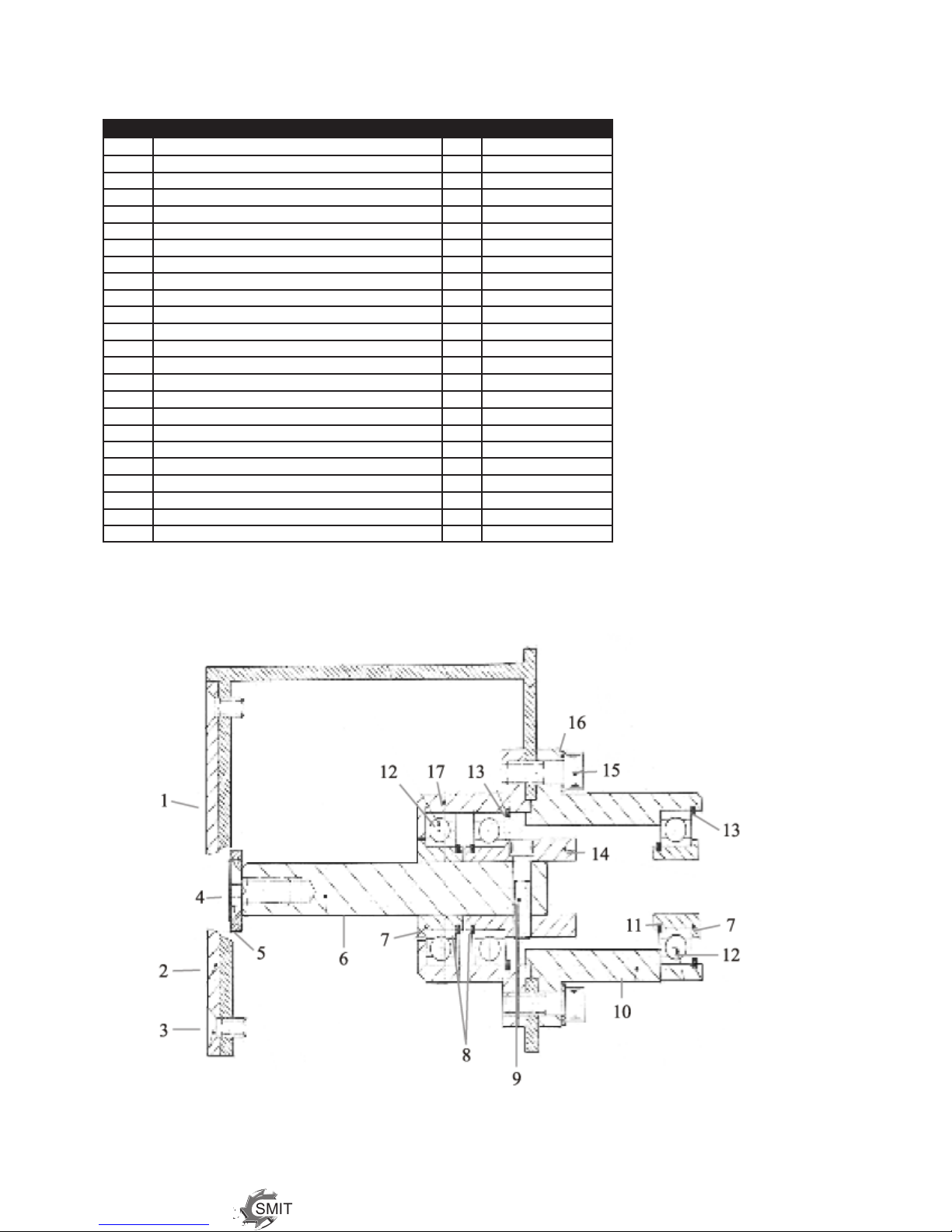
Edger Assembly
Item Description Oty. Part Number
Edger Assembly c/wBareDrum 500.2020.1
Edger Assembly c/w Carbide Cutter Drum 500.2020.2
1 ChassisMk1FS200 1 511.1030
ChassisMk2FS200 1 511.1064
ChassistosuitVonArxFR200 1 511.1050
Chassis to suit Airtec RT200 1 511.1065
2 Cover Plate 1 511.1031.1
Cover Plate tosuitVonArxFR200/AirtecRT200 1 511.1054
3 SocketCountersunkScrewM6x16 4 982.1007.16
4 Securing Washer Screw 1 982.1008.25
5 Securing Washer 1 506.1006.1
6 Shaft 1 513.1001.2
7 Hexagon Driving Support 2 514.1000
8 Internal Circlip 30 mm 2 977.1010.30
9 SocketHeadCapScrewM6x30 1 984.1007.30
10 BearingHousing 1 512.1004
11 External Circlip 30 mm 1 977.1010.30
12 Bearing6006-2RS 1 979.1000.18
13 Internal Circlip 55 mm 1 977.1000.55
14 Long Hexagon Support 1 514.1001
15 SocketHeadCapScrewM8x25 4 984.1008.25
16 Spring Washer M8 4 991.1020.8
17 BearingHousing 1 512.1003
This manual suits for next models
1
Table of contents
Popular Power Tools manuals by other brands


HIKOKI
HIKOKI M1808DA Handling instructions

norbar
norbar TTi20 instructions

Metabo
Metabo W 2200-230 Original instructions

Harbor Freight Tools
Harbor Freight Tools Chicago Electric 91082 Assembly and operating instructions

Clarke
Clarke Strong-Arm CSA20F Operation & maintenance instructions

Princess auto
Princess auto 8408197 user manual


