Smith Realiser A16 Use and care manual

Installing new firmware to your Realiser A16
Rev 1.80 Dec 12 2019
Updating your A16 with rev 1.80 Dec 12 2019 is only necessary if your A16’s firmware is older. The
current revision of your firmware is found in SETTINGS>UPDATES/ABOUT as described below in step 5. If
an update is required please begin with STEP 1.
Issues addressed in this update
1) The defunct ‘Auto Mute’ feature has been changed to ‘Preset Mute’ and sets the mute window
immediately following a change of preset or audio source. It can be programmed from 1 to 3
seconds.
2) The HP-A and HP-B SPDIF and the Tactile outputs are now correctly muted during power up and
when changing presets or audio source. However, for the SPDIF outputs, the method
implemented at present simply grounds the bi-phase signal on mute. This will cause
downstream SPDIF receivers to unlock while mute is active, which may result in minor audible
artefacts during mute/unmute transitions. In the future we may improve on this by muting the
PCM before to encoding, rather than the SPDIF signal itself.
3) A channel swap on the stereo tactile output has been fixed.
4) The minimum HPEQ sweep amplitude has been reduced to avoid clipping when the headphone
gain switches are set to medium or high gain positions.
5) The minimum PRIR sweep amplitude has been reduced to better accommodate high gain sound
systems.
6) If the loading of user A or user B presets fails to complete (usually as a result of a power outage
during the loading process) the A16 will not attempt to automatically reload such presets until
they are manually loaded via the preset menu page. This is done to avoid a lock-out situation
whereby the unit would continually reload corrupted preset files. Reinstalling the firmware or
restoring factory settings will not circumnavigate this requirement. If either user A or user B
presets remain unloaded, some, or all, of the functionality of the A16 is disabled, so it is
important to recognised when this has happened. For example, if the user B preset remains
unloaded after power up, the solo/mute and level meters will not function for user A or user B.
To alert users to the fact that a preset remains unloaded, a ‘reload’ warning will now appear in
the home page for whichever preset needs attention.

7) Head trackers running rev 1.09 Aug 06 2019 and earlier can lose their thermal calibration data
after a period of use, causing the azimuth angle to rotate uncontrollably. When this happens the
LED atop the head tracker does not illuminate. We have traced this problem to insufficient data
protection in the event that power is removed during writes to the internal calibration tables.
This update includes new head tracker firmware rev: 1.20 Nov 08 2019 that protects against this
risk and also introduces a new fall-back optical-only tracking mode that can be used even in the
absence of valid calibration data. Please see “Updating the Head Tracker firmware” at the end
of this document in order to update the firmware in your head tracker. Please note, if your head
tracker’s LED has stopped turning on then it will need recalibrated even after the new head
tracker firmware has been installed. Please see “Re-calibrating the Head tracker” at the end of
this document for undertaking this procedure. We have tested the stability of the new head
tracker firmware to power loss for over 8 weeks now, without issue. As such, we are confident
that once re-calibrated, you will not need to repeat the operation for the foreseeable future.
A16 Firmware update procedure
STEP 1. The new firmware for the Realiser A16 is uploaded through the micro-SD card slot on the front
panel. First, obtain a micro-SD card (commonly 16 GB) and ensure it is formatted as FAT32. Second,
create a ‘realiser’ folder in the root directory and copy the firmware file FIRMA001.SVS into the realiser
folder. Insert this micro-SD card into the slot on the front of your A16.
STEP 2. Power up the A16 ensuring the power indicator LED is steady green. You can power it up using
the remote control or by momentarily depressing either User A or User B volume knobs. Now turn off
the A16 by pushing in and holding in the User A volume knob for at least 3 seconds. The LCD screen will
switch off and the power indicator LED will turn red. Release the User A volume knob.
STEP 3. Push in and hold in the User B volume knob and, simultaneously, push in and release the User A
volume knob. Then release the User B volume knob. The action of holding in B and depressing A
activates the firmware update manager as shown below. The power indicator LED will also be blinking
green.

STEP 4. Using the remote control, press the ENTER key twice to begin the firmware update. The A16 will
enter a long period (20-25 minutes) of authenticating the software, loading and rebooting. When the
unit first reboots it will begin updating the firmware for the individual hardware modules. After the
individual firmware modules have been reprogrammed the unit will reboot using the normal power-up
sequence to the Speaker Map display for User A.
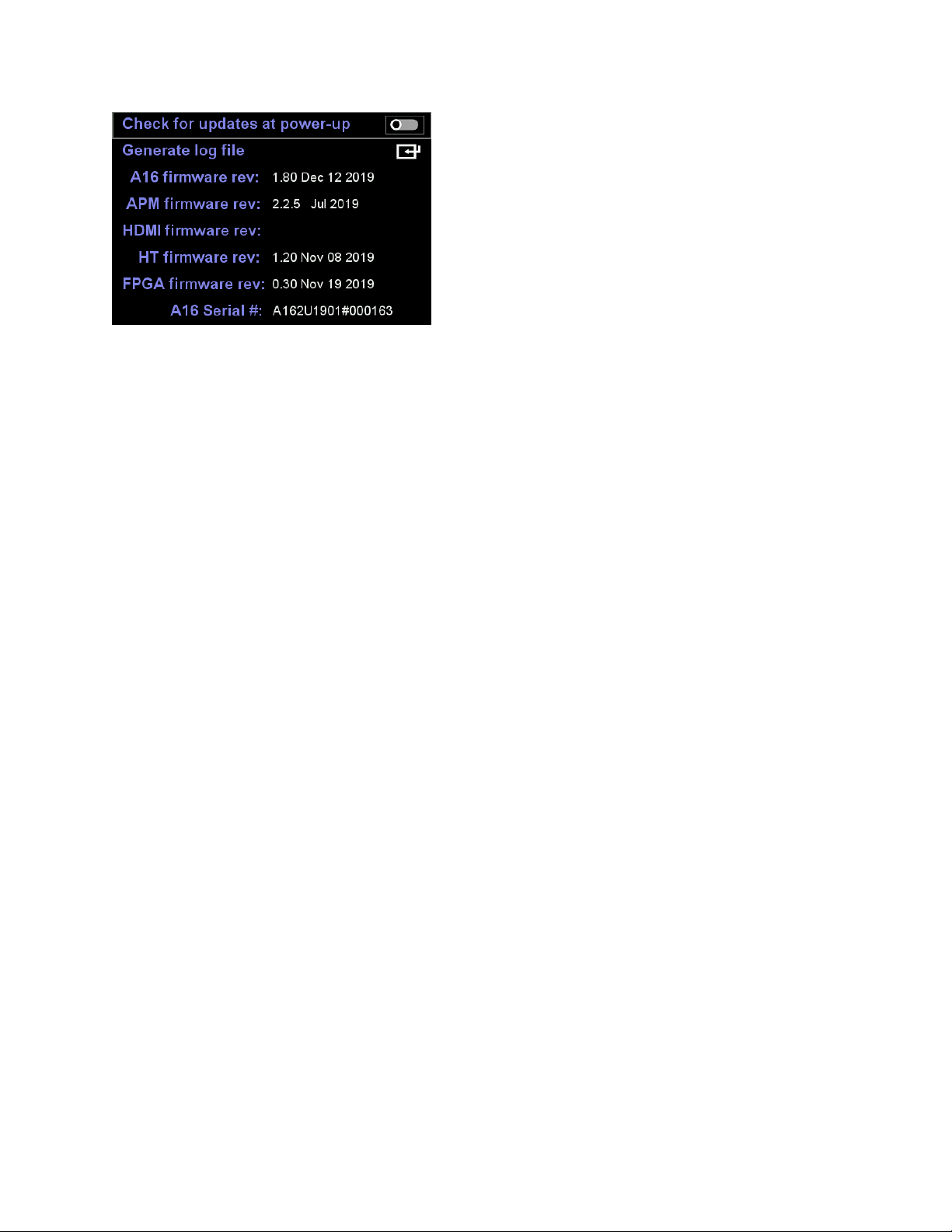
STEP 5. To confirm the firmware update was a success please check the revision numbers displayed in
UPDATES/ABOUT accessed via the SETTINGS page.
Confirm the A16 firmware revision is 1.80 Oct 15 2019 and that the FPGA firmware revision is 0.30 Nov
19 2019. The new head tracker firmware 1.20 Nov 19 2019 will not be displayed here until you run
Update HT firmware. All other software modules are unchanged from the previous firmware update.
STEP 6. The firmware update is now complete. However, for rev 1.80 it is also necessary to run a ‘Full
factory restore ’ to ensure all settings, room and preset formats are also updated. This step will
overwrite all User A and User B Presets 1-16 as well as all Atmos/DTS:X/PCM sound rooms 1-32 and all
PRIR/HPEQ measurements held in the recycle memory. If required, save any measurements in the
recycle memory to the internal storage memory before proceeding. Internal storage for PRIR and HPEQ
files is not affected by a full factory restore. A full factory restore will not always be required following a
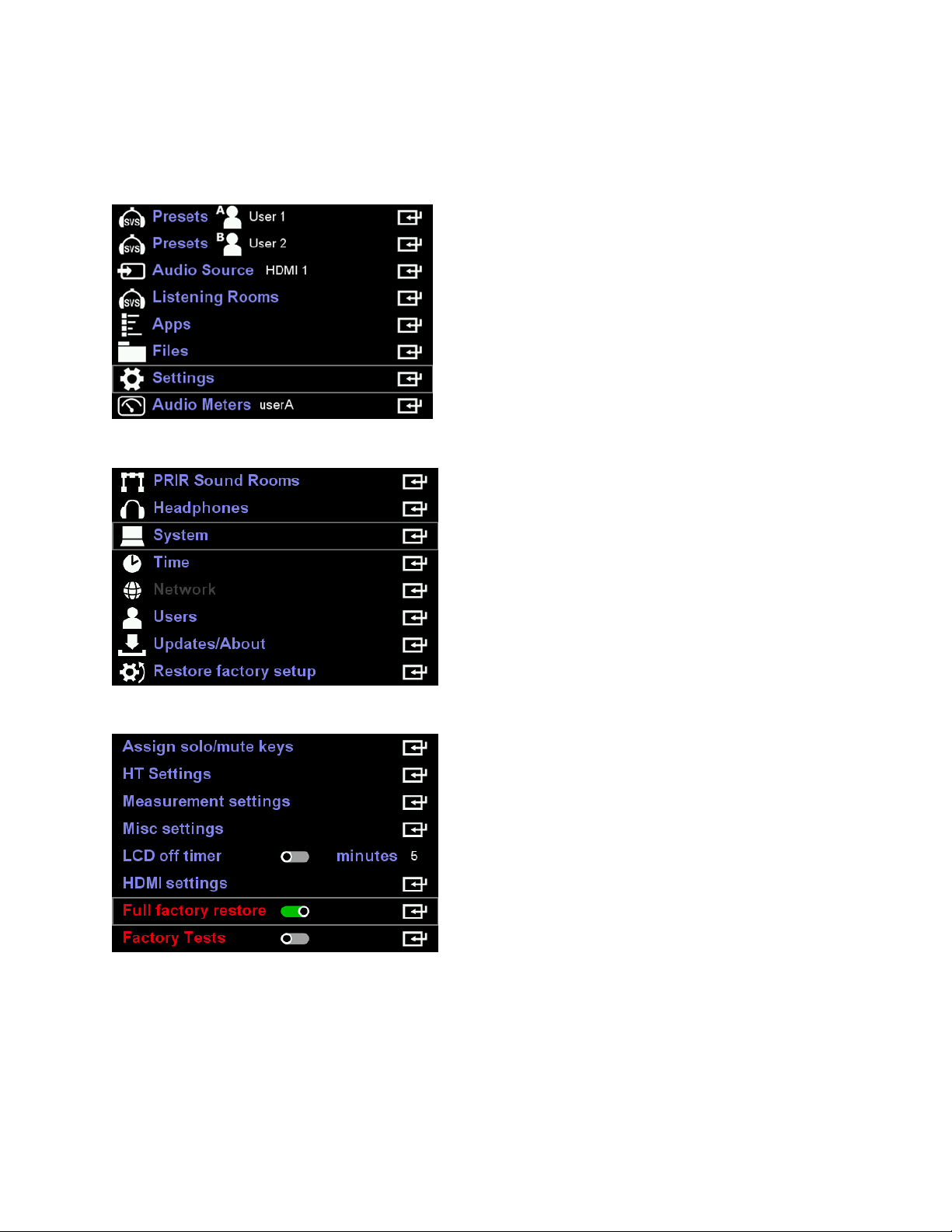
firmware update. It is a requirement for rev 1.80 due to changes in the file formatting for the internal
listening rooms and presets. First press BACK and then navigate to ‘Settings’ and press ENTER.
Then navigate to ‘System’ and press ENTER again.
Move the cursor down to Full factory restore and enable it using the ADJ+ key. Now press Enter.
The full factory restore will take approximately 30 minutes to complete, thereafter the A16 will
automatically return to the User A Speaker Map display.
New features in this update
1) Asynchronous PRIR measurement mode
The asynchronous PRIR measurement method (ASYNC) is now fully operational in this firmware
release. Furthermore, both synchronous (ALL) and asynchronous (ASYNC) PRIR methods can
measure azimuth and elevation looks. Although PRIR files can now include elevation look data,
we have not yet completed the SVS virtualiser program that can make use of this data. Hence
the current SVS virtualiser will only make use of the azimuth look data in azimuth-elevation PRIR
files for now.
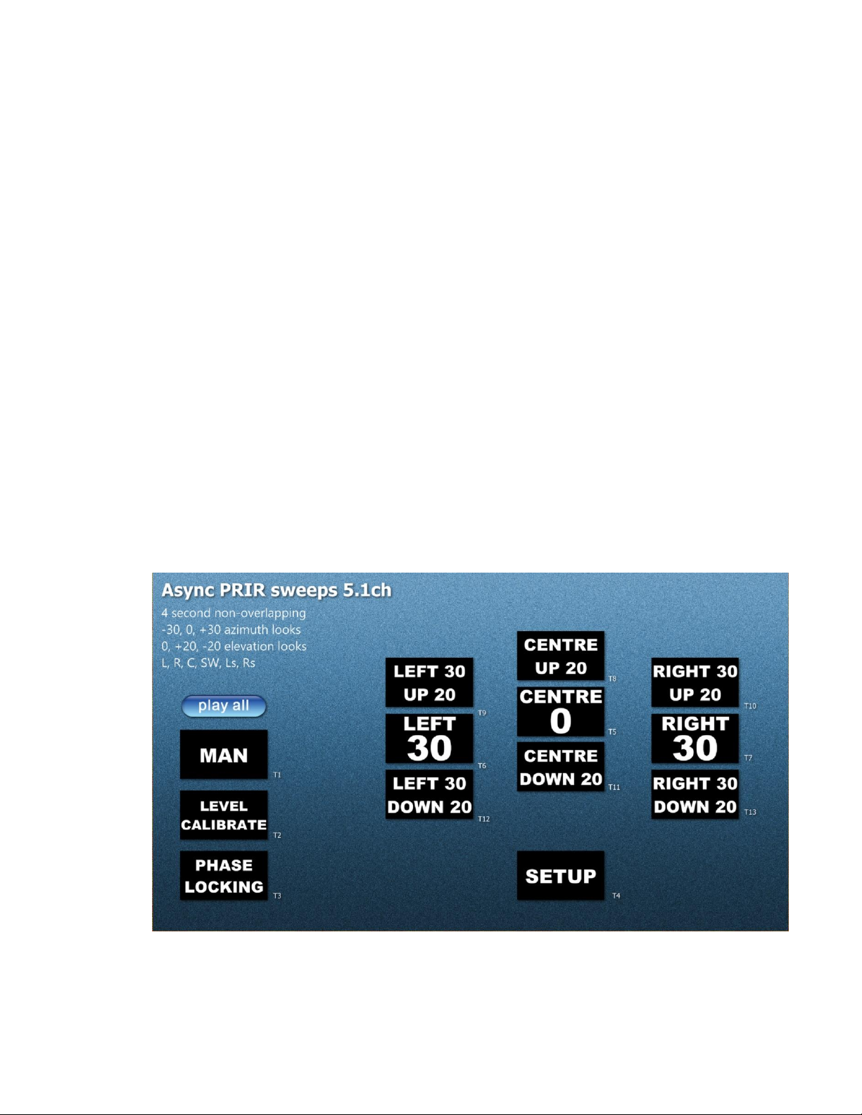
Below is a menu shot of a 5.1ch PCM measurement suite that plays from a USB drive or SD card
plugged into a Blu-ray or equivalent player. We plan to create a number of different speaker
setups and look angle combinations covering stereo all the way to 9.1.6ch. These video files will
be made available for download from our website in due course. A YouTube video explaining
the async PRIR procedure will also be available in the near future.
The 5.1ch measurement suite shown below measures a 5.1ch speaker setup for three azimuth
angles (centre, left 30 degrees and right 30 degrees) and two elevation angles (up 20 degrees
and down 20 degrees)

Before you begin the ASYNC measurement, one of the PRIR Sound Rooms, under Settings,
should be configured to match the real sound room to be measured. In the 5.1ch example
above, the speaker order is given as L,R,C,SW,Ls and Rs. Hence the speakers listed in the PRIR
sound room should match this order.
The Azi/Elev angles of the speakers should be edited to approximate the positions of the
speakers in the real room with respect to the sweet spot. When an ASYNC PRIR measurement is
made, the sound room location, the room description and the speaker setup Azi/Elev angles are
all copied from the selected PRIR sound room to the PRIR file.
In the Apps home page select the sound room that describes the room to be measured.
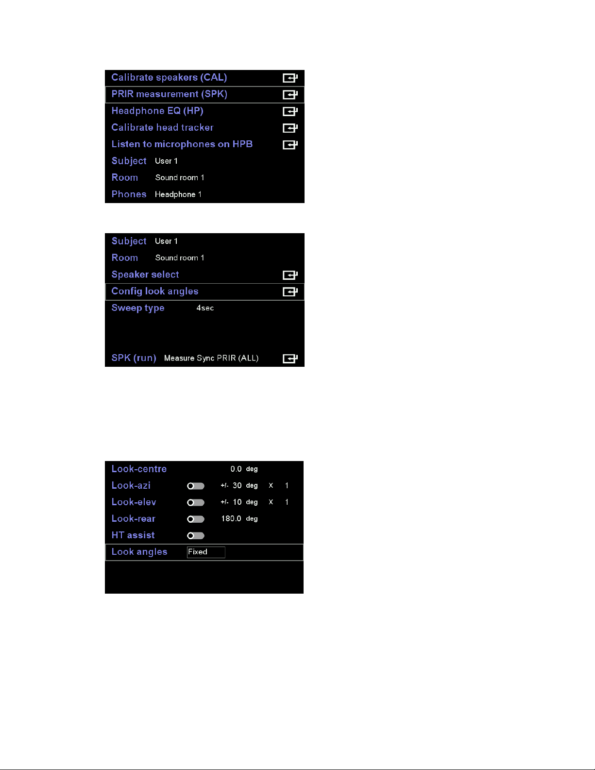
Next configure the look angle mode. There are only two choices relevant for ASYNC
measurements. Either Look angles are Free or Fixed. When the look angles are fixed then the
look angles inserted into the async PRIR file are those supplied by the measurement suite file –
in this example those angles are 0, -30, +30, +20, -20 degrees.
When the look angles are free, then the angles from the head tracker are used to populate the
async PRIR file.
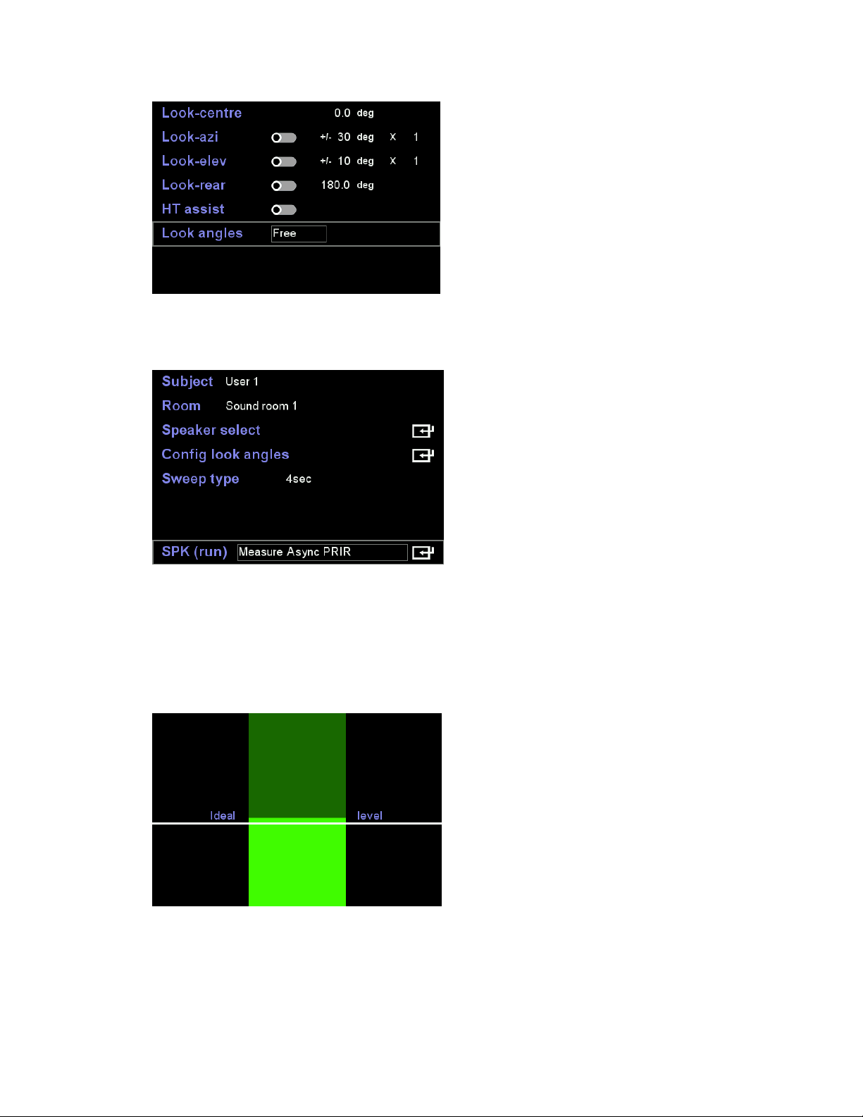
Begin the process by selecting Measure Async PRIR and pressing enter.
The first screen is used to set the loudness of the sound system. Insert the in-ear microphones,
sit in the sweet-spot, play the MAN noise track (T1) and adjust the volume until the levels
average around the white line.
Press enter once you are happy with the level. Next play the Level Calibrate track (T2). The
system will automatically detect when the track begins and the LEVEL CALIBRATION banner will
appear on the A16 screen as shown below. This track consists of short sweeps played to each

loudspeaker and the A16 finds the optimal microphone gain that maximizes the signal to noise
ratio. This calibration should be undertaken in silence and with the subject looking towards the
centre speaker.
On completion of the level calibrate track, play the Phase Locking track (T3). Again, this is
automatically detected by the A16. The purpose of this track is to allow the A16 to adjust its
sample clock to match that of the players. This adjustment is required to maximize the quality of
the resulting PRIR. In the example below the phase locking finishes with an average drift
between the A16 and the video player of 0.2 samples per second, or 2 samples every 10
seconds. This calibration should be undertaken in silence and the subjects head should remain
stationary throughout.
On completion of the phase locking, play the Setup track (T4). Again, this is automatically
detected by the A16. The purpose of this track is to transfer the speaker setup, embedded in the
video track, to the A16.

On completion of the setup track, the A16 display should now show the speaker setup that will
be measured.
Once you are ready you can start the async PRIR measurement by playing the first look track
Centre 0 (T5). The subject should position their head according to the voice instructions. For
each look track a sweep is output to each loudspeaker in sequence.
Proceed to play all the remaining look tracks (T6,7,…T13) positioning your head according to the
voice prompt.
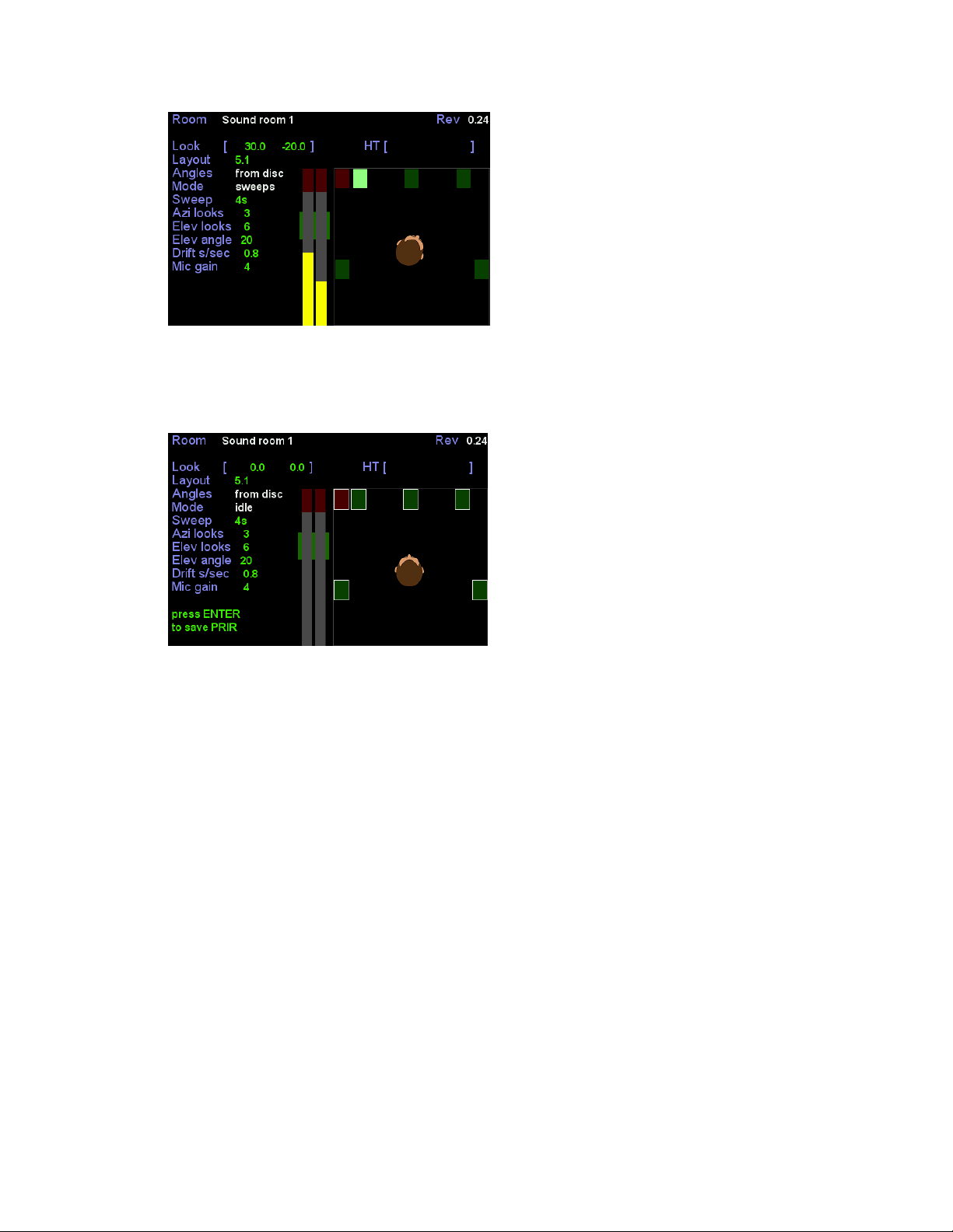
On completion of the final track (T13) all look angles will have been measured and a white box is
drawn around each measured speaker. Press enter to save the PRIR to a file.
2) Changes to the Synchronous (ALL) PRIR measurement mode
a) Activating HT assist now forces the look-mode to ‘fixed’. Fixed means that the look angles
inserted into the PRIR file are a direct copy of those defined in the look-angle menu.
b) HT assist mode also activates the pilot tone to help guide the subject’s head to the required
look angle. There are three tones output in this mode depending on the selected pilot axis.
On first entering the PRIR routine the pilot tone defaults to the azimuth axis. This outputs
the mid-frequency tone to the speakers the output level of which steadily reduces as the
head tracker angle gets closer to the desired azimuth look angle. This reduction in volume
begins once the head tracker is within +/-20 degrees of the desired look azimuth angle.
Once the head tracker matches the look angle then the tone is muted. The pilot tone for the
elevation axis can be selected by pressing either the up-arrow key or down-arrow key. In
this mode the pilot tone frequency is high if the head tracker elevation angle is higher than
the desired look elevation angle or low if the head tracker elevation is too low. As with the
azimuth pilot tone, both high and low pilot tones decrease in volume as the head tracker
gets closer to the desired look elevation angle. This reduction in volume begins once the
head tracker is within +/-20 degrees of the desired look elevation angle. Pressing the left-
arrow or right-arrow keys switches back to the azimuth axis pilot. The purpose of having the

azimuth and elevation pilot tones separated in this way is to allow the subject to switch
between axes and iteratively find the head angle that minimises the volume of the tone for
both axes. The method in previous firmware revisions activated the elevation pilot tone
automatically once the azimuth angle was close to the desired angle –a method which we
have deemed too confusing.
c) Previously using HT assist the PRIR sweeps would begin automatically once the correct head
angle had been obtained. Now the user must press the enter key to trigger the sweeps.
d) Vertical look angles can now be measured.
e) English language voice prompts have been added that specify the desired head position for
each look. In ‘free’look angle mode, the voice prompts are still driven by the look angles
defined in the look-angle setup menu (same as ‘fixed’), but the user is free to look any angle
they wish. However, since ‘free’ look angle mode always requires the user to deploy the
head tracker, it is the head tracker angles that will be inserted into the PRIR rather than
those defined in the look-angle menu.
f) Pause Enable halts the PRIR measurement after each look. Press OK to trigger the sweeps
for the next look.
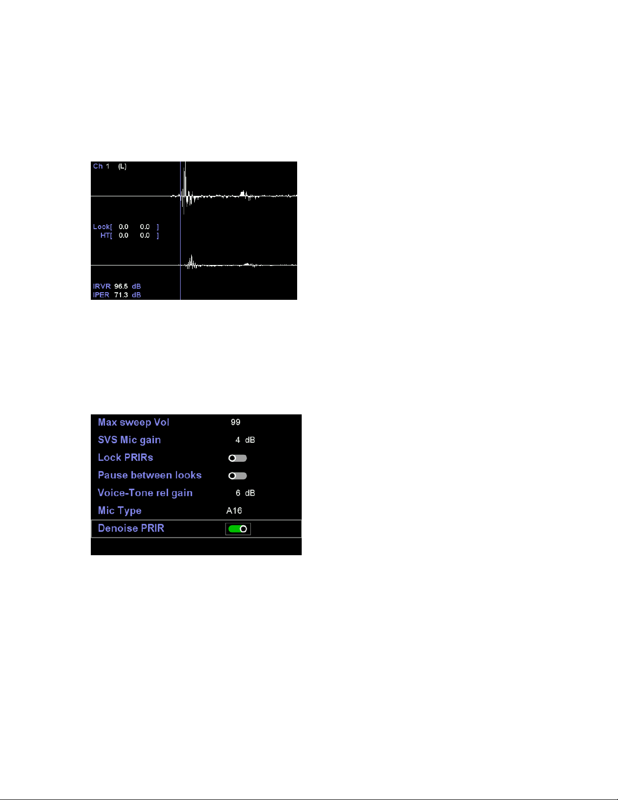
3) PRIR viewer for intra-measurement quality assessment
The PRIR viewer is intended to provide a means of visually assessing the quality of a PRIR
measurement as it is in the process of being measured, or at the end of a measurement just before
it is written back as a PRIR file.
Most PRIR measurements consist of a series of sweep measurements made at a number of discrete
look angles. By allowing the measurement to pause between looks, it is possible to view the pre and
post onset regions of the impulse response captured for each speaker. This allows the subject to
abandon the measurement early in the process if the impulse data is deemed flawed and not have
to wait until the entire measurement has finished.
The PRIR viewer can be used for both synchronous (ALL method) and asynchronous (ASYNC method)
PRIR measurements. For the ALL method, the measurement will pause between looks if either HT-
Assist or Pause-between-looks is active. Since each look in the ASYNC method is a separate track on
the blu-ray disc or USB drive, examination of the PRIR impulses can be made on a track by track
basis. An example of the PRIR viewer screen is shown below. A more complete explanation is shown
on our YouTube channel.
4) PRIR denoise function
Denoise PRIR is controlled in the measurement setting page. It defaults to on.
Fundamentally the noise floor of a PRIR measurement is a function of the ambient noise level of the
sound room being measured, the noise level of the in-ear microphones, the energy of the sinewave
sweeps and the sweep duration. In studio conditions our 12-second sweep measurements can attain
signal-to-noise ratios of around 112dB (a 4-second sweep will on average be 5dB higher at 107dB).
Noise in a PRIR is not perceived as noise in the conventional sense but as low-level reverberation. As
such, it would be more accurate to describe the quality of the PRIR as having a peak-to-residual
reverberation ratio of 112dB.This means that in a virtual room the reverberation will at best decay
to 112dB below peak listening level, whereas in a real room the reverberation essentially decays to
zero. The upper trace of the diagram below illustrates this residual reverberation phenomenon
which shows the raw PRIR reverberation energy as a function of time over the Realiser’s 0.75 second
convolution window. The measured room has a reverberation time of around 0.25 seconds and the
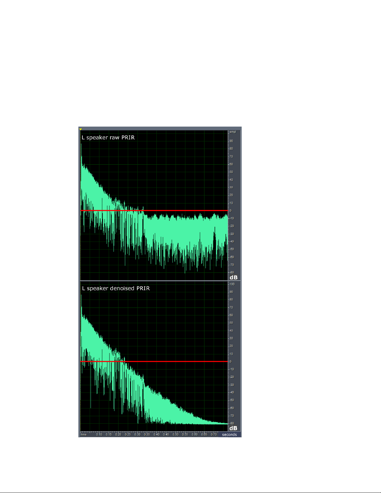
final 0.4 of the PRIR is just residual noise, albeit 100dB below peak. Fortunately, low level
reverberation of this order is difficult to perceive under normal listening conditions and therefore a
good measurement made under ideal conditions will essentially be indistinguishable from the real
room. Nonetheless, ideal conditions are often not attained in practice and the use of 12 second
sweeps can make measurement sessions exceedingly lengthy occasions. For this reason, we have
added a denoising signal processing function that results in a virtual room reverberation decay that
follows that of the room under measurement, as depicted in second trace in the diagram below.
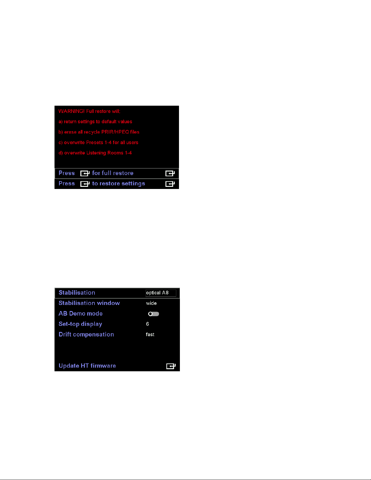
5) Factory restore
Factory restore menu has been split into two options a) full factory restore b) restore only the
settings. For either restore operations the User and Headphone text descriptor fields are no
longer overwritten.
6) Raw optical-only head tracking mode
A raw optical head tracking mode of operation has been included in head tracker firmware rev:
1.20 Nov 08 2019. This mode is similar to the A8 head tracker except that the operating range
has been increased to +/-65 degrees. The optical A8 mode must be used in conjunction with the
set-top, similar to the regular optical stabilisation mode.

7) Editing the descriptor fields in existing PRIR and HPEQ files
The filename, layout and subject fields for internal PRIR files can now be edited using the standard
text entry method up to a maximum of 32 characters for each. The filename, headphone and
subject fields for internal HPEQ files can also be edited in the same way. Furthermore, the
filenames of internal PRIR and HPEQ files, created as a result of a PRIR or HPEQ measurements,
now begin with the subject’s name. Use of the ‘PRIR’ and ‘HPEQ’ headers has been dropped. The
new naming convention is as follows.
For measured PRIR files: Up to the first 13 characters of the subject field + up to the first 16
characters of the location field + up to the first 8 characters of the layout field.
For measured HPEQ files: Up to the first 13 characters of the subject field + up to the first 16
characters of the headphone field.
In both cases, ‘up to’ means that fewer characters will be copied if the end of the text string is
encountered first.
8) New naming convention for PRIR/HPEQ files written to SD
When internal PRIR and HPEQ files are written to the micro SD card, the following filename
convention is now used.
For PRIR files: ‘PRIR’ + up to the first 32 characters of the internal filename field + [ time and date
when the measurement was taken ] + timestamp when the file was written to the SD card.
For HPEQ files: ‘HPEQ’ + up to the first 32 characters of the internal filename field + [time and
date when the measurement was taken] + timestamp when the file was written to the SD card.
In both cases, ‘up to’ means that fewer characters will be copied if the end of the text string is
encountered first. Invalid filename characters < > ? * : are automatically replaced by spaces,
except for / \ which are replaced by [ ] respectively.
Known Issues being Investigated
User B Head Tracking does not function in Optical mode
Head tracking for User B is limited to none-stabilized or magnetic-stabilized modes at present.
Optical head tracking will be extended to both users in due course.

Audible clicks when changing/jumping tracks on Atmos BluRay discs
Audible clicks can often be heard when changing/transitioning tracks on Atmos BluRay discs.
Initial investigations suggest it is related to the HDMI board switching modes outside its own
audio mute window.
A16 powers up with White screen or Black screen
For a few A16s the LCD display does not always initialize properly during powerup. This can
result in either a completely white screen or completely black screen and can only be remedied
by power cycling the unit.
After firmware updates the display shows a red screen with error code 002/003
As the A16 exits a firmware update for the first time it can sometimes trigger a communications
timeout that results in the unit halting and displaying error code 002/003. This is not a fault as
such and normal operation will continue once the power has been cycled.
From time to time the A16 halts and displays a red screen with an error code 002/003
This results from a communication timeout between the main processor and the DSP chips
running the SVS virtualization. Power must be cycled in order to get things running again. The
vast majority of A16s in the field are not affected by this issue. However, for rev 1.80 firmware
we have reduced the speed of this communication bus which, we believe, will reduce the
likelihood of this issue.
Sometimes the A16 becomes sluggish and may even stop responding to the remote control
We are still in the early states of this investigation. We have never seen this problem here in the
factory but reports in the field suggest the problem may occur when sound rooms are being
repeatedly configured and reloaded to their presets, but we don’t know for sure. The few
owners who have encountered this problem find that it is necessary to reload the firmware to
restore normal operation. This issue may be related to a mismatch between the firmware and
the listening room file formats which arise if a factory restore is not run following a new
firmware installation. Please ensure that following the installation of firmware rev 1.80 Dec 12
2019, you run a Full Factory Restore, as described earlier in this document.

Updating the Head Tracker firmware
The HT firmware updater programs the head tracker firmware stored in the A16 into the head tracker
via the HT cable. This internal firmware file is delivered as part of the A16 firmware update and as such
is invisible to the user. The steps to update the head tracker firmware are as follows.
Step 1) Plug the head tracker into the User A side HT jack.
Step 2) Go to Settings>System>HT settings>Update HT firmware and press enter to start the update.
This causes the internal firmware file to be flashed to the head tracker. The A16 display and the LED
atop the HT report the progress of the update procedure in the following order. The entire process takes
about 60 seconds to complete.
A16 display status
HT LED status
1
Loading application
No change
2
Connecting to HT (may be brief)
Red+Green steady
3
Update in progress
Red flashing
4
Authenticating update
Red+Green steady
5
HT update validated
10 flashes (Green, or Red, or alternating)
Step 3) Once the A16 status displays ‘HT update validated’, repeatedly press the back key to exit the
update routine and return to the home screen. The A16 will be unresponsive momentarily while the
Presets for user A and user B are reloaded.
Step 4) Go to Settings>Updates/About and check that the reported HT firmware revision is 1.20 Nov 08
2019.
If the HT firmware update fails to follow the order shown above, for example it stalls at ‘Connecting to
HT’, or alternates between ‘Loading application’ and ‘Connecting to HT’ then the communication with
the HT has failed. First, fully exit the Update HT firmware menu and unplug the head tracker. Then
restart beginning step one.
Immediately following the update and following every power up, the LED atop the head tracker will flash
10 times. If the head tracker is correctly calibrated it will flash green 10 times or alternating red-green 5
times. If the head tracker has lost its thermal calibration data it will flash red 10 times and in this case
the head tracker must be re-calibrated for correct operation.
Re-calibrating the Head tracker
If the LED atop your head tracker no longer illuminates (RED or GREEN) when plugged into the A16, or
after installing the new 1.20 Nov 08 2019 HT firmware, it flashes red 10 times after power up, then it
requires thermal re-calibration as described below. If you have not already done so, please ensure you
have updated to HT firmware to rev: 1.20 Nov 08 2019 or later before proceeding.
Step 1) Unplug the head tracker and place in a freezer (-18 deg C) for 20-30 minutes to ensure the starting
temperature of the head tracker is below 5 deg C.
Step 2) Have the A16 powered up and situated in a room at normal room temperature (18-35 deg C) and
have both user A and user B presets loaded and running.
Step 3) Remove the head tracker from the freezer and immediately plug it into the HT jack input of User
A. During the calibration process the head tracker must not move or vibrate. As such, place the head
tracker on a solid surface. As the internal temperature passes 8 deg C the LED atop the HT will turn red
and begin blinking once a second.
Step 4) As the head tracker temperature slowly climbs to the ambient room temperature it continues
taking thermal readings every second (blinking LED). Once the internal temperature plateaus the LED will

turn green (blinking) indicating that the calibration is complete. The entire process may take up to 25
minutes.
Step 5) Once the head tracker is blinking green pick it up and, with the LED now on steady green, unplug
the 2.5mm jack. Now reconnect the 2.5mm jack. Immediately following power-up the LED will either flash
green 10 times, or it will flash alternating red-green 5 times. Both sequences imply the calibration was
successful. If the LED flashes red 10 times, then the calibration was unsuccessful and the process must be
repeated beginning from step 1).
--------------------------------------------------------------- END --------------------------------------------------------------------
Other manuals for Realiser A16
3
Other Smith Recording Equipment manuals


