miniDSP Dirac DDRC-22A User manual

miniDSP Ltd –Hong Kong / Email : info@minidsp.com / Features and specifications subject to change without prior notice 1
DIRAC SERIES
HIGH-RESOLUTION AUDIO PROCESSORS
WITH DIRAC LIVE®TECHNOLOGY
User Manual
DDRC-22A
DDRC-22D

miniDSP Ltd –Hong Kong / Email : info@minidsp.com / Features and specifications subject to change without prior notice 2
Revision history
Revision
Description
Date
0.9
Initial public release
26 Mar 2014
1.0
First production version
4 April 2014

miniDSP Ltd –Hong Kong / Email : info@minidsp.com / Features and specifications subject to change without prior notice 3
TABLE OF CONTENTS
Important Information......................................................................................................................................... 5
System Requirements ...................................................................................................................................... 5
Disclaimer/Warning ......................................................................................................................................... 5
Warranty Terms............................................................................................................................................... 5
Package Contents ............................................................................................................................................ 6
A Note on this Manual ..................................................................................................................................... 6
1 Product Overview.......................................................................................................................................... 7
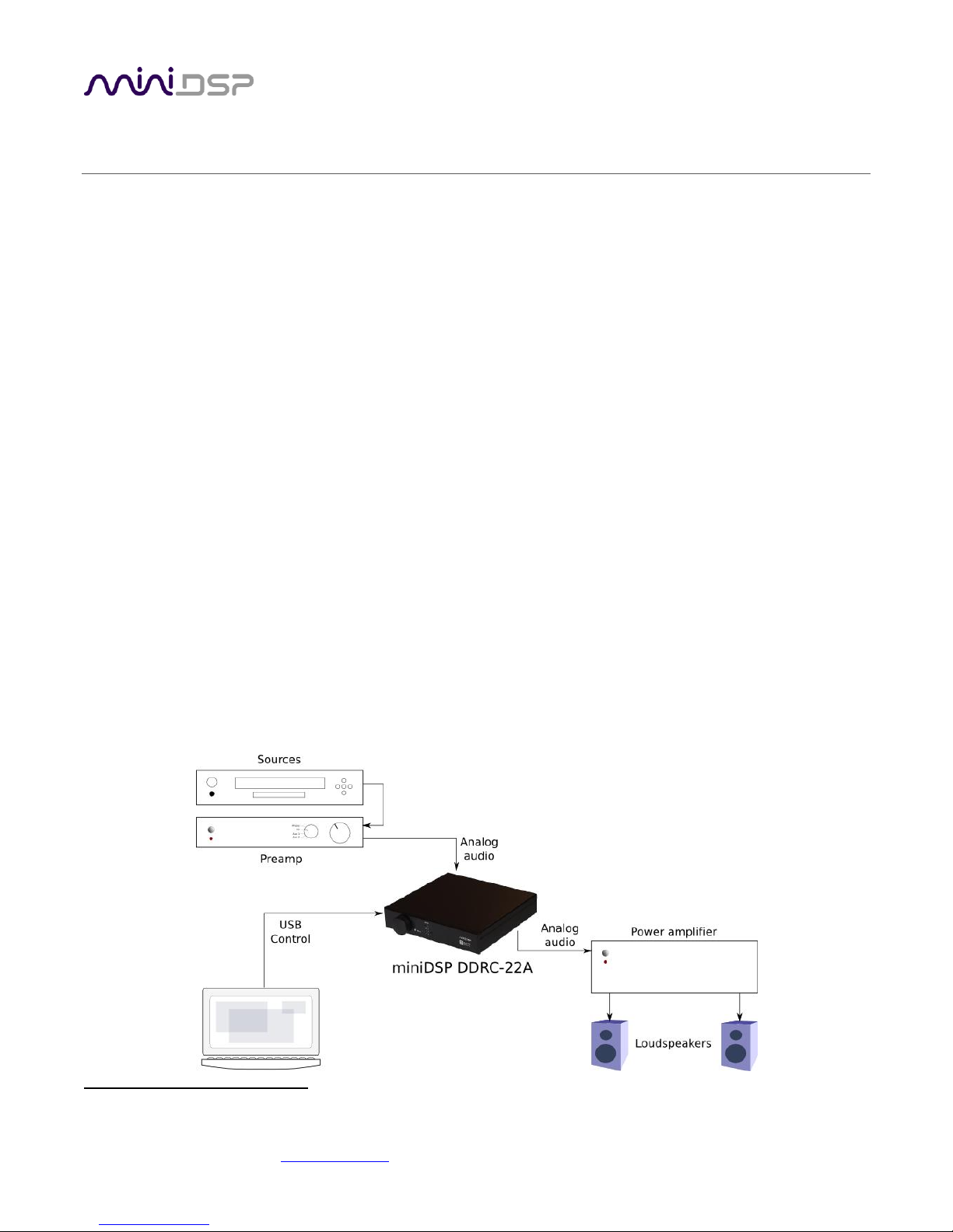
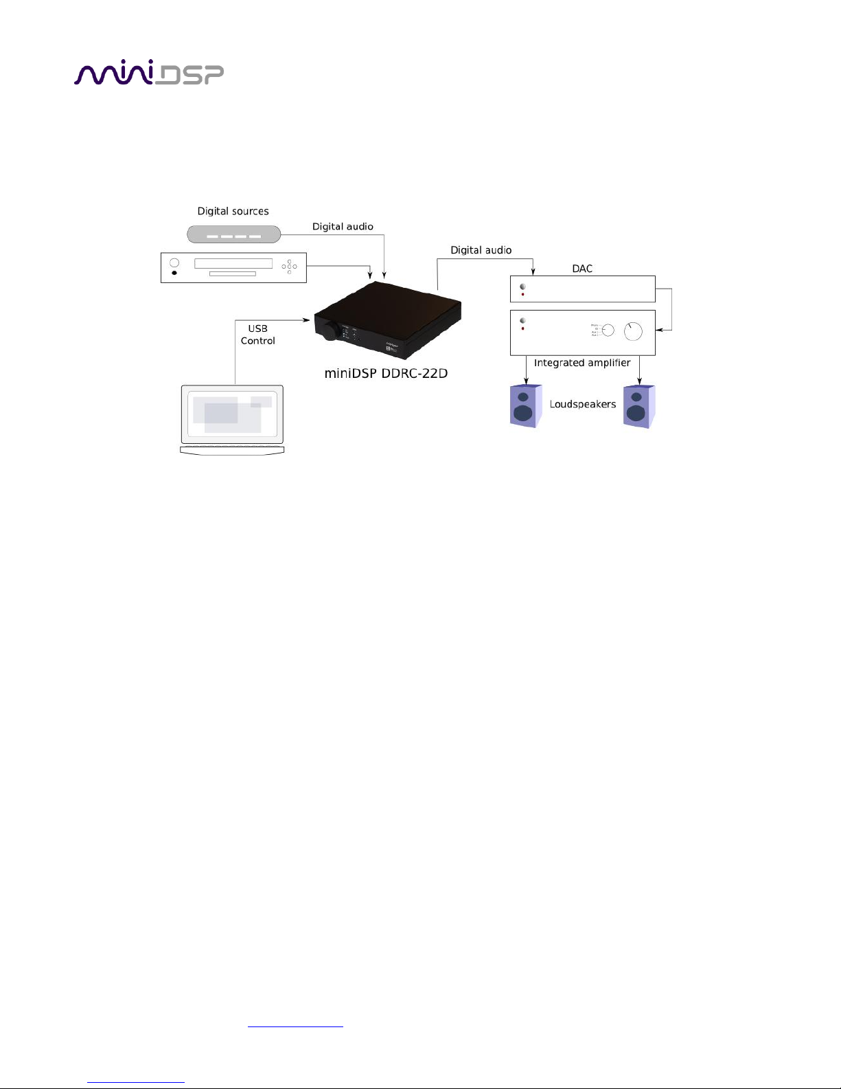
1.1 Typical system configurations............................................................................................................... 7
1.2 How Dirac Live® works ......................................................................................................................... 8
1.3 The Dirac Series / Dirac Live® design process ...................................................................................... 10
2 Installation and Setup.................................................................................................................................. 11
2.1 Hardware connectivity ....................................................................................................................... 11
2.1.1 Digital audio connections (DDRC-22D) ........................................................................................ 11
2.1.2 Analog audio connections (DDRC-22A)........................................................................................ 11
2.1.3 DC Power.................................................................................................................................... 12
2.1.4 USB............................................................................................................................................. 12
2.2 Software installation and license activation........................................................................................ 13
2.2.1 Framework installation ............................................................................................................... 13
2.2.2 Software installation................................................................................................................... 13
2.2.3 License activation ....................................................................................................................... 13
2.2.4 License validation ....................................................................................................................... 14
3 Acoustic Measurement................................................................................................................................ 15
3.1 Loudspeaker and microphone positioning .......................................................................................... 15
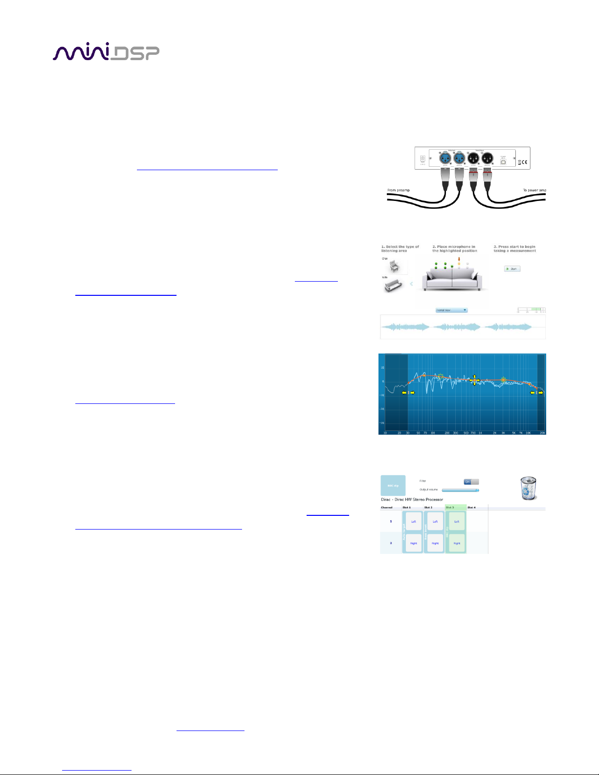
3.2 Connections for acoustic measurement.............................................................................................. 16
3.3 Configuring for measurement............................................................................................................. 17
3.3.1 Sound System tab ....................................................................................................................... 18
3.3.2 Mic Config tab ............................................................................................................................ 18
3.3.3 Output & Levels tab .................................................................................................................... 19
3.4 Running the measurements................................................................................................................ 20
3.4.1 Listening environment ................................................................................................................ 20
3.4.2 Executing measurements............................................................................................................ 21
3.4.3 Viewing and redoing measurements........................................................................................... 22
3.4.4 Completing the measurements................................................................................................... 22
3.5 Saving and loading projects ................................................................................................................ 22
4 Filter Design ................................................................................................................................................ 23
4.1 Working with graphs .......................................................................................................................... 23
4.2 Designing your target curve................................................................................................................ 25
4.2.1 The Auto Target.......................................................................................................................... 25
4.2.2 Editing the target curve .............................................................................................................. 26
4.2.3 Guidelines for target curve design .............................................................................................. 27
4.2.4 Saving and loading target curves................................................................................................. 28

miniDSP Ltd –Hong Kong / Email : info@minidsp.com / Features and specifications subject to change without prior notice 4
4.3 Generating correction filters............................................................................................................... 28
4.4 Downloading and managing filter sets................................................................................................ 29
5 Using the Dirac Series audio processor ........................................................................................................ 31
5.1 Status indicators................................................................................................................................. 31
5.2 Front panel controls ........................................................................................................................... 31
5.3 Infrared remote control...................................................................................................................... 32
6 Additional Information ................................................................................................................................ 33
6.1 Specifications ..................................................................................................................................... 33
6.2 Troubleshooting ................................................................................................................................. 34
6.3 MCU Firmware upgrade ..................................................................................................................... 35
6.4 Obtaining Support .............................................................................................................................. 36

miniDSP Ltd –Hong Kong / Email : info@minidsp.com / Features and specifications subject to change without prior notice 5
IMPORTANT INFORMATION
Please read the following information before use. In case of any questions, please contact miniDSP at
SYSTEM REQUIREMENTS
To configure your Dirac Series audio processor, you will require a Windows PC with the following minimum
specification:
Intel Pentium III or later, AMD Athlon XP or later
2 Gigabytes (GB) of RAM or higher
Keyboard and mouse or compatible pointing device
Microsoft• ® Windows® Vista® SP1/Win7/Win8
Microsoft• ® .NET framework v3.5 or later
Two free USB 2.0 ports
DISCLAIMER/WARNING
miniDSP cannot be held responsible for any damage that may result from the improper use or incorrect
configuration of this product. Please read this manual carefully to ensure that you fully understand how to
operate and use this product, as incorrect use or use beyond the parameters and ways recommended in this
manual have the potential to cause damage to your audio system.
Please also note that many of the questions we receive at the technical support department are already
answered in this User Manual and in the online application notes on the miniDSP.com website. So please take
the time to carefully read this user manual and the online technical documentation. And if an issue arises with
your unit, please read through the Troubleshooting section first. Thank you for your understanding!
WARRANTY TERMS
miniDSP Ltd warrants this product to be free from defects in materials and workmanship for a period of one
year from the invoice date. Our warranty does not cover failure of the product due to incorrect connection or
installation, improper or undocumented use, unauthorized servicing, modification or alteration of the unit in any
way, or any usage outside of that recommended in this manual. If in doubt, contact miniDSP prior to use.

miniDSP Ltd –Hong Kong / Email : info@minidsp.com / Features and specifications subject to change without prior notice 6
PACKAGE CONTENTS
Your Dirac Series package includes:
One Dirac Series high-resolution audio processor
One universal 5 VDC power supply with interchangeable power pins
One USB cable for computer connectivity
One UMIK-1 calibrated measurement microphone with USB cable
One tripod microphone stand
One license for Dirac Live Calibration Tool Stereo for miniDSP
One printed Quick-start Guide
ANOTE ON THIS MANUAL
This User Manual is designed for reading in both print and on the computer. If printing the manual, please print
double-sided. The embedded page size is 8 ½” x 11”. Printing on A4 paper will result in a slightly reduced size.
For reading on the computer, we have included hyperlinked cross-references throughout the manual. In
addition, a table of contents is embedded in the PDF file. Displaying this table of contents will make navigation
much easier:
In Adobe Reader on Windows, click on the “bookmarks” icon at the left. The table of contents will appear on
the left and can be unfolded at each level by clicking on the “+” icons.
In Preview on the Mac, click on the View menu and select Table of Contents. The table of contents will
appear on the left and can be unfolded at each level by clicking on the triangle icons.

miniDSP Ltd –Hong Kong / Email : info@minidsp.com / Features and specifications subject to change without prior notice 7
1PRODUCT OVERVIEW
Thank you for purchasing a Dirac Series 24/96
1
high-resolution audio processor powered by Dirac Live®, the
world’s premier room correction solution. We are delighted to offer you this software and hardware
combination, the fruit of extensive research and development and years of experience in sound system tuning.
Deploying a miniDSP Dirac Series 24/96 audio processor with Dirac Live® Technology will
Improve the imaging of your sound system
Improve the clarity of the music
Produce a tighter bass
Reduce listening fatigue
Improve the timbre
Remove resonances and room modes
Reduce early reflections
Dirac Series processors are available in different versions. The DDRC-22A has analog inputs and outputs, while
the DDRC-22D has digital inputs and outputs. Each is inserted into the signal chain in the appropriate location
(see below for examples).
1.1 TYPICAL SYSTEM CONFIGURATIONS
The DDRC-22A (analog input/output) is typically inserted into the analog signal chain just before power
amplification, such as between a preamp or mixing/mastering console and power amp. Since it has on-board
volume control, it can also be used in systems where there is no other volume control, such as between a CD
player and a power amplifier.
1
All Dirac Series processors operate with 24-bit 96 kHz resolution.

miniDSP Ltd –Hong Kong / Email : info@minidsp.com / Features and specifications subject to change without prior notice 8
The DDRC-22D (digital input/output) is typically inserted into the digital signal chain just before D/A conversion;
for example, between one or more digital sources and a DAC. From there, a regular power amplifier or an
integrated amplifier complete the system. Variants on this theme include the use of an integrated amplifier with
a digital input or the use of a digital input of an A/V receiver, in which case a separate DAC is not required.
Computer connectivity is used to perform acoustic measurements and generate digital room correction filters.
Up to four sets of correction filters can be stored on the Dirac Series processor and recalled from the front panel
or via an infrared remote. Once the processor is fully configured, the computer is no longer needed.
1.2 HOW DIRAC LIVE®WORKS
Each model in the miniDSP Dirac Series of audio processors includes Dirac Live®, a premium mixed-phase room
correction technology. This technology is used not only in home stereo systems but also in cinemas, recording
studios, and luxury cars.
As with any room correction system, Dirac Live® corrects the system’s magnitude response (often referred to
imprecisely as “frequency response”). In contrast to fully automated systems, Dirac Live® corrects the
magnitude response towards a user-adjustable target response. The target response takes account of the
natural frequency range of the loudspeaker system and the normal effects of loudspeaker dispersion on the
measured in-room magnitude response.
In addition, Dirac Live® corrects the system’s impulse response, which reflects how the system responds to a
sharp transient such as a drumbeat. Reflections, diffraction, resonances, misaligned drivers, and so on, all
combine to smear out the transient. An ideal loudspeaker has none of these, so correcting the impulse response
makes the speaker in the room behave much more like that ideal loudspeaker. The impulse response is a critical
factor for accurate sound-staging, clarity and bass reproduction. Dirac Live® employs a sophisticated analysis
algorithm to make the optimal correction across the whole listening area, not just at a single point.
Differences between the impulse responses of the two loudspeakers at the listening position will also affect
soundstage and imaging. The more similar the impulse responses, the more easy it is to “trick”the brain into
thinking that the loudspeakers are not really there, and that the sound emanates from a virtual stage spanned
by the physical speakers.

miniDSP Ltd –Hong Kong / Email : info@minidsp.com / Features and specifications subject to change without prior notice 9
Dirac Live® accomplishes this using mixed-phase filters –filters that match a desired magnitude response and
generate a customized impulse response. This contrasts with the minimum-phase and linear-phase filters that
are commonly used in audio applications. While minimum-phase and linear-phase filters are relatively easy to
design, they are tightly constrained in their impulse response characteristics –neither can make a desired
change to the magnitude response independently of controlling the impulse response. In some cases, they may
even make things worse.
Mixed-phase filters are more difficult to design, but the audible performance of Dirac Live® is due to its success
in using mixed-phase filters to make the system response across the whole listening area more closely resemble
that of an ideal speaker. The energy from the direct wave and from early reflections is optimally combined to
arrive as a single wavefront to the listener. Late reflections are left largely untouched, being corrected only for
their spectral coloration, as they contribute to a larger, more enveloping soundstage.
Illustration of Dirac Live® magnitude response correction
Illustration of Dirac Live® impulse response correction

miniDSP Ltd –Hong Kong / Email : info@minidsp.com / Features and specifications subject to change without prior notice 10
1.3 THE DIRAC SERIES /DIRAC LIVE®DESIGN PROCESS
The design process for optimizing your system with the Dirac Series audio processor and Dirac Live® is
summarized as follows:
1. Connect the Dirac Series audio processor into your system and install
software. See Section 2, Installation and Setup.
2. Run a series of acoustic measurements using the Dirac Live
Calibration Tool Stereo for miniDSP program, to capture the
acoustic behavior of your speakers and room. See Section 3,
Acoustic Measurement.
3. Generate digital room correction filters that will be executed by
the Dirac Series processor. Up to four filter sets can be downloaded
into the processor for easy real-time recall and auditioning. See
Section 4, Filter Design.
4. Once the digital room correction filters are designed and
downloaded, the computer can be disconnected, as computer
connectivity is not required for normal listening. See Section 5,
Using the Dirac Series audio processor.

miniDSP Ltd –Hong Kong / Email : info@minidsp.com / Features and specifications subject to change without prior notice 11
2INSTALLATION AND SETUP
2.1 HARDWARE CONNECTIVITY
All connections to the Dirac Series audio processors are made on the rear panel.
2.1.1 Digital audio connections (DDRC-22D)
Connect up to three digital sources to the DDRC-22D inputs: AES-EBU on XLR, S/PDIF on RCA, or optical
(TOSLINK). Connect one of the digital outputs to your DAC or other device with a digital input. All digital outputs
are simultaneously active, so multiple output connections can be made if necessary.
The digital outputs of the DDRC-22D operate at 96 kHz sample rate. Any connected DAC must support
this sample rate. (The digital inputs of the DDRC-22D accept any sample rate up to 216 kHz.)
2.1.2 Analog audio connections (DDRC-22A)
Connect the analog inputs to your preamp or other analog source. Connect the analog outputs to your
amplification. All analog connections are via balanced XLR connectors, so in the event that your other
equipment has only single-ended (RCA) connections, use suitable RCA-XLR adapters or adapter cables.

miniDSP Ltd –Hong Kong / Email : info@minidsp.com / Features and specifications subject to change without prior notice 12
2.1.3 DC Power
The supplied 5 VDC power supply includes a set of interchangeable power pins. Fit the correct pins for your
country. Connect the DC plug to the 5 VDC power socket.
2.1.4 USB
Computer connectivity is required to perform acoustic measurements in your listening room and to generate
and download the digital room correction filters to the Dirac Series processor. To configure the processor,
connect the USB port of the processor to a USB 2.0 port on your computer using the supplied cable. For
measurements, connect the UMIK-1 to a second USB port.
Once calibration and configuration is complete, the computer can be disconnected. The processor can then be
controlled from the front panel or via remote control –see Using the Dirac Series audio processor.

miniDSP Ltd –Hong Kong / Email : info@minidsp.com / Features and specifications subject to change without prior notice 13
2.2 SOFTWARE INSTALLATION AND LICENSE ACTIVATION
2.2.1 Framework installation
Prior to installing the software, download and install the following frameworks. You will need to accept the
license agreements in order to successfully complete the installation. If you haven’t updated these recently,
check that you have the latest versions prior to running the miniDSP install programs.
Microsoft .NET framework (version 3.5 or later)
Latest version of Adobe Flash
Latest version of Adobe Air
Microsoft Visual C++ 2010 Redistributable Package: for x86 (32-bit operating system) or x64 (64-bit operating
system).
2.2.2 Software installation
When you receive notification that your order has shipped, your installation software downloads will be
available at the User Downloads section of the miniDSP website, under the Dirac Series heading.
http://www.minidsp.com/userdownloads
Download two installation zip files: the Dirac Live Calibration Tool Stereo version for miniDSP, and the DDRC
Configuration Plugin. Unzip each file and double-click to run each installer. Follow the on-screen instructions to
complete installation.
2.2.3 License activation
1. Start the miniDSP DDRC-2x2 utility program. It will appear as shown on the left below.
2. Connect your Dirac Series processor to your computer via USB, then click on the Connect button. It will
change to a green tick.
3. Click on Get Activation Serial Number. The program will get your unique serial number from the connected
DDRC and display it, as shown on the right below.

miniDSP Ltd –Hong Kong / Email : info@minidsp.com / Features and specifications subject to change without prior notice 14
4. Using this serial number, activate your license on the Dirac Series activation page:
http://www.minidsp.com/dirac-series/activate/#activate
If you have not purchased a Dirac license before, use the New User screen on the left. If this is not your first
Dirac license, use the screen on the right.
Note: if you purchase more than one Dirac Series processor, each will need to be activated with its unique serial
number. Use the screen on the right and enter the serial number of each processor, and they will in turn be
added to your license.
2.2.4 License validation
Start the Dirac Live Calibration Tool Stereo for miniDSP program. It will ask you to validate your software
license. Enter the license credentials that you obtained in the above step, and then click on Validate:
You will need to be connected to the Internet to validate your license. Any active firewalls will need to have
HTTP (normal web traffic) enabled.

miniDSP Ltd –Hong Kong / Email : info@minidsp.com / Features and specifications subject to change without prior notice 15
3ACOUSTIC MEASUREMENT
The Dirac Live Calibration Tool Stereo for miniDSP uses a set of measurements made in your listening room to
calculate correction filters for the left and right channels. The measurements are made using the Dirac Series
audio processor and the supplied UMIK-1 measurement microphone. No additional hardware or connectivity is
required.
3.1 LOUDSPEAKER AND MICROPHONE POSITIONING
Prior to performing acoustic measurements, loudspeaker and listening positions should be optimized. Some
experimentation will be required to obtain the results that you think best, starting with the recommendations of
the loudspeaker manufacturer. With Dirac Live®, you have more freedom with loudspeaker placement but the
best result will still be achieved if optimal loudspeaker placement is used together with Dirac Live®.
Many loudspeakers perform best away from the walls, both the front wall (behind the loudspeakers) and the
side walls. Experiment with toe-in –many loudspeakers benefit from pointing directly at the listening position or
even slightly in front. The listening position should also be away from the rear wall, as placing the listening chair
or sofa right against the wall will result in increased early reflections and changes in timbre.
A total of nine measurements must be taken, with the microphone located in different positions in the room
and pointed between the two speakers. The first measurement must be taken at the central location of the
listening area, as this location sets the levels and delays of each speaker. Usually, this location will be an equal
distance from both speakers but it is not necessary –Dirac Live® will adjust if it is not. Eight more measurements
are then taken at locations spread around the listening room and at different heights from the floor.

miniDSP Ltd –Hong Kong / Email : info@minidsp.com / Features and specifications subject to change without prior notice 16
3.2 CONNECTIONS FOR ACOUSTIC MEASUREMENT
The figure below shows a typical connection diagram for performing acoustic measurement. (This example uses
the DDRC-22D.) No changes to existing audio connections are needed. Simply:
1. Connect the supplied USB (type A to type B) cable from the processor to a USB port on the computer.
2. Connect the supplied USB (type A to mini type B) cable from the UMIK-1 to a USB port on the computer.
Place the UMIK-1 microphone into the microphone stand. Position the computer and cabling so that there is
enough freedom of movement to move the microphone into the needed locations.

miniDSP Ltd –Hong Kong / Email : info@minidsp.com / Features and specifications subject to change without prior notice 17
3.3 CONFIGURING FOR MEASUREMENT
Start Dirac Live Calibration Tool Stereo for miniDSP (if it is not already running).
The main areas of the screen are:
Logo and status progress bar
This area shows a progress bar with current status when the program is performing calculations.
Screen selection tabs
Each tab selects a screen that is shown in the main display area. These are generally worked
through in order, from top to bottom. This section covers the first four tabs; the final two are
covered in Filter Design.
Load and save a project
Each measurement project can be saved to a file and reloaded at a later time. See Saving and
loading projects.
Back to previous / proceed to next
Use these two buttons to advance to the next screen when each is complete, or to go back to
the previous screen to make alterations. The tabs at the left can also be clicked on directly.
Help open/close
Click on the small Help divider at the right of the screen to open a pane with help on the
currently selected tab. Click on the divider again to close the help pane.

miniDSP Ltd –Hong Kong / Email : info@minidsp.com / Features and specifications subject to change without prior notice 18
3.3.1 Sound System tab
The Sound System tab is preset for you, provided that you have your Dirac Series audio processor and UMIK-1
connected to the computer via USB.
Choose system configuration
Preset to Stereo Speaker System. This is the only configuration supported by current Dirac
Series processors.
Test signal playback device
Preset to DDRC-22 (miniDSP Ltd). This will ensure that test signals are sent into your audio
system via the Dirac Series processor. (If this is not present, check that your Dirac Series
processor is connected via USB and powered on, and click the Rescan button.)
Once you have verified that this screen is correct, click the Proceed button.
3.3.2 Mic Config tab
On the Mic Config tab, set the following parameters.
Recording device
Preset to the UMIK-1. (If this is not present, ensure that
the UMIK-1 is connected securely to the computer via
USB, and go back to the Sound System tab and click on
Rescan. Then select the “Microphone” item underneath
“UMIK-1”, as shown at right.)
Recording channel
Select 1from the drop-down menu.

miniDSP Ltd –Hong Kong / Email : info@minidsp.com / Features and specifications subject to change without prior notice 19
Microphone calibration file
Each UMIK-1 measurement microphone is individually calibrated to ensure accuracy. To
download the unique calibration file for your microphone, go to the UMIK-1 page and enter your
microphone's serial number. It is in the form xxx-yyyy and labelled on the microphone. Use
"Save As" in your browser to save the data to a text file –for example, UMIK-7001870.txt.
Then click on the Load File button and select your calibration file.
Once you have verified that this screen is correct, click the Proceed button.
3.3.3 Output & Levels tab
On the Output & Levels tab, set Output volume quite low. If you have another volume control “down-stream”
of the DDRC, set it about halfway (or -20 dB if digital) and increase it later if needed.
Click on the Test button for the left channel and gradually increase the output volume until it is at a moderate
level, such that your voice would have to be raised to converse with someone sitting next to you.
Now increase the Input gain slider until the blue bar on the level meter reaches up into the green section, as
shown below.
Click again on the Test button for the left channel to stop the test signal. Then click on the Test button for the
right channel. If necessary, adjust Input gain or Output volume so that both channels are in the green.
When done, click the Proceed button.

miniDSP Ltd –Hong Kong / Email : info@minidsp.com / Features and specifications subject to change without prior notice 20
3.4 RUNNING THE MEASUREMENTS
Measurements are performed on the Measurements screen.
3.4.1 Listening environment
The Dirac Live Calibration Tool Stereo for miniDSP presents two different listening environments as a visual
guide to positioning the microphone for each measurement: Chair, for a single listening seat, and Sofa, for
multiple listening seats. Select a listening environment by clicking on the chosen icon.
The center of the screen contains a pictorial representation of the selected listening environment, with dots
marking the microphone locations. Completed measurements are shown in green, while the next measurement
to be done is highlighted in yellow and has a red arrow marker pointing to it. A drop-down menu underneath
selects three different views, which should be used to help you place the microphone in the correct location.
This manual suits for next models
1
Table of contents
Other miniDSP Recording Equipment manuals