Smokaroma Bar-B-Q Boss Guide
Broaster Company
2855 Cranston Road, Beloit, WI 53511-3991
608/365-0193 broaster.com
© 2017 Broaster Company
Printed In U.S.A.
Smokaroma® is a registered trademark.
Be sure ALL installers read, understand, and have access to this manual at all times.
Design Certified By:
UL, CUL & NSF
SERVICE & PARTS MANUAL
Bar-B-Q Boss®Pressure Smoker
Models BC71 and BC73
Manual #17897 7/17


W-1
FOR YOUR SAFETY
Do not use or store gasoline or other flammable vapors
or liquids in the vicinity of this or any other appliance.
Improper installation, adjustments, alteration, service or maintenance can cause
property damage, injury or death. Read the installation, operating and mainte-
nance instructions thoroughly before installing or servicing this equipment.
For the sake of safety and clarity, the following words used in this manual are defined as follows:
Indicates an imminently hazardous situation which, if not avoided, could
result in serious injury or death.
Indicates a potentially hazardous situation which, if not avoided, could
result in serious injury or death.
Indicates a potentially hazardous situation which, if not avoided, could
result in minor injury, property damage or both.
All adjustments and repairs shall be made
by an authorized Smokaroma representa-
tive.
If there is a power failure, turn the timer
knob to "0" .
Failure to read and
understand this manual
completely could result in serious injury
or death. Be sure ALL operators read,
understand and have access to this
manual at all times.
Rags or paper containing
cooking oil can catch fire
if exposed to heat. Laundering will not
remove the oil. Dispose of all oil-soiled
papers and rags in a trash container that
is in a ventilated area away from all
cooking equipment or other heat
sources such as direct sunlight.
broaster.com Manual #17897 7/17


i
TABLE OF CONTENTS
1. Warning Labels ....................................................................................... 1 - 1
2. ELECTRICAL POWER SUPPLY ................................................................................... 2 - 1
WIRING DIAGRAM 1 PHASE .................................................................................. 2 - 2
WIRING DIAGRAM 3 PHASE .................................................................................. 2 - 3
3. CONTROL PANEL ......................................................................................................... 3 - 1
4. ELECTRICAL COMPONENTS ....................................................................................... 4 - 1
5. PARTS ............................................................................................................................. 5 - 1
CABINET & PANELS ................................................................................................ 5 - 1
BASE ......................................................................................................................... 5 - 2
PRESSURE AND EXHAUST SYSTEM .................................................................... 5 - 3
CONTROL PANEL .................................................................................................... 5 - 4
HEATING ELEMENTS AND INSULATION .............................................................. 5 - 5
COOKING WELL ...................................................................................................... 5 - 6
LOWER CONTROL BOX .......................................................................................... 5 - 7
COVER ASSEMBLY ................................................................................................. 5 - 8
MEAT RACK ............................................................................................................. 5 - 9
TIERED FOOD BASKET ........................................................................................ 5 - 10
broaster.com Manual #17897 7/17

1 - WARNING LABELS
1-1
broaster.com Manual #17897 7/17


2 - ELECTRIC POWER SUPPLY
2-1
broaster.com Manual #17897 7/17
ELECTRICAL SAFETY
Many parts of this section
pertain to checking and re-
pairing electrical components. High Voltage
will be encountered in several instances.
Only persons trained and equipped for
checking high voltage shall undertake such
repairs.
If no component operates, check main pow-
er supply. Be sure main circuit breaker is ON
and main fuses are good.
Correct voltage is specified on the specifi-
cation plate located on the rear panel. It will
be either 208V or 240V for domestic units
and 220V for export units.
If the unit will not turn on, perform the follow-
ing:
1. Disconnect main power supply.
2. Be sure all connections are tight. If
power supply is proper, see TROU-
BLESHOOTING section.
ACCESS FOR SERVICE
For access to the electrical compartment,
remove rear cover.

2-2
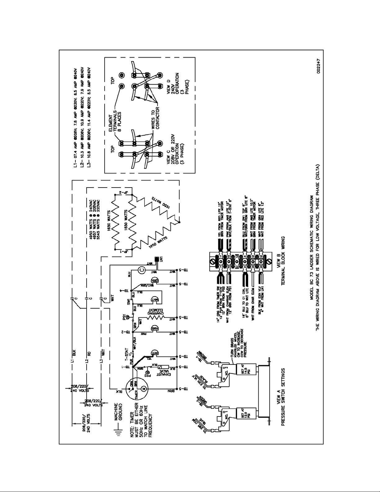
208V, 220V & 240V 1ph:
broaster.com Manual #17897 7/17
2-3
broaster.com Manual #17897 7/17
208V, 220V & 240V 3ph:

3 - CONTROL PANEL
3-1
broaster.com Manual #17897 7/17
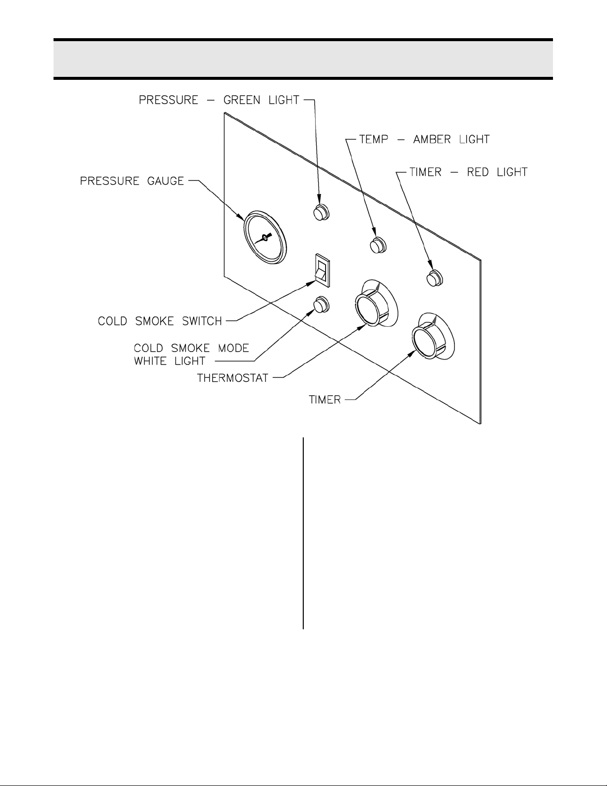
THERMOSTAT: Puts the smoker in either
BAR-B-Q or HOLD mode. When set, pro-
vides power to the power relay/contactor to
the heating elements.
COLD SMOKE SWITCH: Puts the smoker
into Cold Smoke Mode.
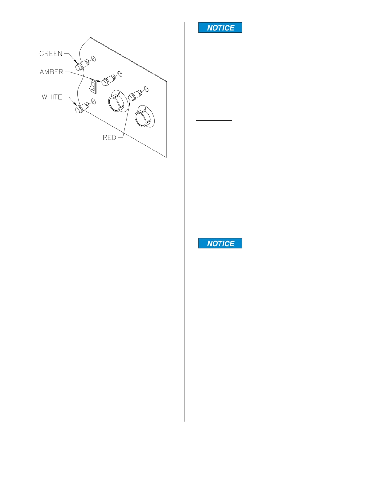
COLD SMOKE - WHITE LIGHT: Illumi-
nates when the TIMER and THERMOSTAT
are set and the COLD SMOKE SWITCH is
on.
PRESSURE GAUGE: Indicates the pres-
sure present in the Cooking Well.
PRESSURE - GREEN LIGHT: Illuminates
when the THERMOSTAT and TIMER are set
and the COLD SMOKE SWITCH is off. And
also when Pressure Switch #1 is closed
sending power to the elements.
TEMPERATURE - AMBER LIGHT: Illumi-
nates when the THERMOSTAT and TIMER
are set and when the thermostat is calling
for heat.
TIMER - RED LIGHT: Illuminates when the
TIMER is set.
TIMER: Sets the product cook time. When
the timer is set, it provides power to the
control circuit.

3-2
ACCESS FOR SERVICE
1. Unplug power cord.
2. Remove rear cover of unit.
broaster.com Manual #17897 7/17

3-3
PRESSURE GAUGE
1. See ACCESS FOR SERVICE.
2. Disconnect the hose from the fitting on
the back of the pressure gauge.
3. Remove the (2) mounting nuts and the
mounting clamp from the gauge.
4. Pull gauge out of control panel from
the front.
5. Remove fitting from back of gauge.
6. Install new pressure gauge in reverse
order.
COLD SMOKE SWITCH
1. See ACCESS FOR SERVICE.
2. Remove blue wires from switch.
3. The switch is removed from the front
of the control panel. To remove the
switch, depress the keepers on the top
and bottom of the switch and push
switch out toward the front of the
panel.
4. To install the new switch make sure
the center pole is toward the right as
you look at the back of the unit. (see
diagram below)
broaster.com Manual #17897 7/17
3-4
LIGHTS
1. See ACCESS FOR SERVICE.
2. Remove the wires from the light being
replaced.
3. Depress the keepers and push the
light out of the control panel.
4. Install the new light in reverse order.
Push light in until the chrome ring is
flush with the front of the control
panel.
TERMINAL BLOCK
Replacing the terminal block can be
done in one of two ways.
Method 1 (recommended)
1. Remove the (2) nuts holding the
block in place then remove the
terminal block leaving the wires
connected to the old block.
2. Mount the new terminal block
and secure with the original
mounting nuts.
Terminals 5 & 6 are jum-
pered together and
should be toward the right end when
facing the back of the control panel.
3. Transfer the wires from one ter-
minal to the same terminal on the
new terminal block.
Method 2
1. Remove the wires from the termi-
nal block.
2. Remove the (2) mounting nuts
and pull out the old terminal
block.
3. Mount the new terminal block
and secure with the original
mounting nuts.
Terminals 5 & 6 are jum-
pered together and
should be toward the right end when
facing the back of the control panel.
4. Reinstall the wires on the new
terminal block. See wiring dia-
grams in section 2 of this manual
for correct wire connections to
the terminal block)
broaster.com Manual #17897 7/17

4 - ELECTRICAL COMPONENTS
4-1
broaster.com Manual #17897 7/17
Many of the components
in this section will have
wires that will need to be connected to
the terminal (TB) the diagram below
shows how the terminals are numbered.
Terminal 5 has a jumper between them to
provide more terminals.
TIMER
Removal:
1. Unplug power cord.
2. Remove rear panel of unit..
3. Remove timer knob from front of panel
by pulling away from panel.
4. Remove timer mounting screws from
front holding the timer in place.
5. Remove timer from panel and discon-
nect the black and orange wires from
the terminal on the timer.
6. Disconnect the (2) brown wires from
the terminal block.
New Timer Installation:
7. Install new timer using mounting
screws removed earlier and connect
wires as shown above.
8. Push knob on to shaft on front of unit.
9. Reinstall rear panel.
10. Plug in power cord to put unit back in
service.

4-2
THERMOSTAT:
Removal & Installation:
1. Unplug power cord.
2. Remove rear panel of unit.
3. Lay unit on its back and loosen the
clamp holding the thermostat bulb in
place.
4. Set unit upright on its casters.
5. Remove thermostat knob from front of
panel by pulling away from panel.
6. Remove thermostat mounting screws
from front holding the timer in place.
7. Disconnect wires from the thermostat.
8. Pull capillary tube and bulb up through
hole in bottom of control box.
9. Thread capillary and bulb of new ther-
mostat down through hole in bottom of
control box.
10. Mount new thermostat to back of panel
using the screws removed earlier.
11. Reconnect wires to thermostat.
12. Install thermostat knob.
13. Lay unit on its back.
14. Insert bulb under clamp on bottom of
cooking well and tighten screw enough
to hold bulb in place.
Tightening screw too much
may damage the bulb.
15. Set unit upright on its casters.
16. Reinstall rear panel.
17. Plug in power cord to put unit back in
service.
broaster.com Manual #17897 7/17

4-3
PRESSURE SWITCHES:
REPLACEMENT:
PRESSURE SWITCH PS1:
When pressure is below its set point, PS1 is
closed, providing power to the power relay/
contactor, which powers the heating ele-
ments.
To remove PS1 it is neces-
sary to remove PS2.
1. Unplug power cord.
2. Remove rear panel of unit.
2. Remove wires from both pressure
switches.
3. Remove pressure switch PS2.
4. Remove pressure switch PS1.
5. Install the new pressure switch.
6. Reinstall pressure switch PS2.
7. Reconnect wires as indicated in the di-
agram at left.
8. Adjust pressure switch PS1 as de-
scribed in the PRESSURE SWITCH
ADJUSTMENT section.
9. Reinstall rear panel.
10. Plug in power cord to put unit back in
service.
PRESSURE SWITCH PS2
When pressure is below its set point, PS2 is
closed providing power to the exhaust
valve, keeping it closed to build pressure.
1. Unplug power cord.
2. Remove rear panel of unit.
3. Remove wires from pressure switch
PS2.
4. Remove pressure switch PS2.
5. Install new pressure switch.
6. Reconnect wires as indicated in the di-
agram at left.
7. Adjust pressure switch PS1 as de-
scribed in the PRESSURE SWITCH
ADJUSTMENT section.
8. Reinstall rear panel.
9. Plug in power cord to put unit back in
service.
broaster.com Manual #17897 7/17

4-4
PRESSURE SWITCH ADJUST-
MENT
1. Put one quart of water in cooker.
2. Place cover on cooking well and tight-
en.
3. Turn power on by setting timer to “1”
hour.
4. If the exhaust valve releases pressure
lower than 14.5 PSI, adjust knurled nut
on the pressure switch clockwise to in-
crease pressure. As the pressure pass-
es 14.5 PSI turn the knurled nut
counterclockwise to activate the ex-
haust valve. Test to insure that the ex-
haust vlave continues to be activated
at 14.5 PSI.
5. Continue to adjust until solenoid valve
maintains a pressure between 14 to15
PSI on the pressure gauge. Try to set it
at 14.5 PSI.
6. Open ejector valve to reduce pressure
in the cooking well to approximately 10
PSI.
7. If the power relay/contactor de-ener-
gizes before the pressure reaches 12
PSI, adjust the knurled nut on PS2
clockwise to re-energize the power re-
lay/contactor. As the pressure passed
12 PSI adjust the knurled nut counter-
clockwise to de-energize the power re-
lay/contactor. Test to ensure that the
power relay/contactor continues to de-
energize at 12 PSI.
broaster.com Manual #17897 7/17
This manual suits for next models
2
Table of contents
Other Smokaroma Smoker manuals


