SMP VetGuardian Manual instruction

A
DEVICE SETUP AND OPERATION
STRUCTURED MONITORING PRODUCTS

NOTICE OF COPYRIGHT INFORMATION
© 2017, Structured Monitoring Products, Inc., Orlando. Florida
All rights reserved to Structured Monitoring Products. This document was designed, prepared, and
submitted by Structured Monitoring Products to be used only by the recipient.

1
Table of Contents
1. Revision History and Change Control.............................................................................. 2
2. Equipment Statements .............................................................................................. 3
3. Setting up the VetGuardian ........................................................................................ 6
4. Install Driver .......................................................................................................... 8
4.1.Running the Kipling Program .................................................................................. 8
5. VetGuardian.......................................................................................................... 11
5.1.Install the Vetguardian Software per the installer file................................................... 11
5.2.Running the VetGuardian Program .......................................................................... 11

2
1. REVISION HISTORY AND CHANGE CONTROL
Date
Reason for Change
Version
10/1/18
Initial Version for Production Release
A
12/20/18
Updated Per Review
B

3
2. EQUIPMENT STATEMENTS
For All Equipment:
Changes or modifications not expressly approved by SMP could void the user's authority to operate the
equipment.1 This device complies with Part 15 of FCC Rules. Operation is subject to the following two
conditions: (1) this device may not cause harmful interference, and (2) this device must accept any
interference received, including interference that may cause undesired operation.
Class B equipment: This equipment has been tested and found to comply with the limits for a Class B
digital device, pursuant to part 15 of the FCC Rules. These limits are designed to provide reasonable
protection against harmful interference in a residential installation. This equipment generates, uses
and can radiate radio frequency energy and, if not installed and used in accordance with the
instructions, may cause harmful interference to radio communications. However, there is no guarantee
that interference will not occur in a particular installation. If this equipment does cause harmful
interference to radio or television reception, which can be determined by turning the equipment off
and on, the user is encouraged to try to correct the interference by one or more of the following
measures: —Reorient or relocate the receiving antenna. —Increase the separation between the
equipment and receiver. —Connect the equipment into an outlet on a circuit different from that to
which the receiver is connected. —Consult the dealer or an experienced radio/TV technician for help.
This device contains an array of SPAD (single photon avalanche diode) detectors and an integrated 940
nm light source based on an eye-safe Class 1 VCSEL (vertical cavity surface-emitting laser). The laser
output is designed to remain within Class 1 laser safety limits under all reasonably foreseeable
conditions including single faults in compliance with IEC 60825-1:2014 (third edition).
Caution: Use of controls or adjustments or performance of procedures other than those specified
herein may result in hazardous radiation exposure

4
Compliance Information for the WiFi module
FCC PART 15 STATEMENTS:
This equipment has been tested and found to comply with the limits for a Class A digital device,
pursuant to Part 15 of the FCC Rules. These limits are designed to provide reasonable protection
against harmful interference when the equipment is operated in a commercial environment. This
equipment generates, uses, and can radiate radio frequency energy and, if not installed and used in
accordance with the instruction manual, may cause harmful interference to radio communications.
Operation of this equipment in a residential area is likely to cause harmful interference in which case
the user will be required to correct the interference at his own expense. The end user of this product
should be aware that any changes or modifications made to this equipment without the approval of the
manufacturer could result in the product not meeting the Class A limits, in which case the FCC could
void the user's authority to operate the equipment.
Compliance Information for the WiFi module in the T7-Pro and T7-Pro-OEM
FCC:
Contains FCC ID: T9J-RN171
This device complies with Part 15 of the FCC Rules. Operation is subject to the following two
conditions: (1) this device may not cause harmful interference, and (2) this device must accept any
interference received, including interference that may cause undesired operation.
This equipment has been tested and found to comply with the limits for a Class B digital device,
pursuant to part 15 of the FCC Rules. These limits are designed to provide reasonable protection
against harmful interference in a residential installation. This equipment generates, uses and can
radiate radio frequency energy, and if not installed and used in accordance with the instructions, may
cause harmful interference to radio communications. However, there is no guarantee that interference
will not occur in a particular installation. If this equipment does cause harmful interference to radio or
television reception, which can be determined by turning the equipment off and on, the user is
encouraged to try to correct the interference by one or more of the following measures:
• Reorient or relocate the receiving antenna.
• Increase the separation between the equipment and receiver.
• Connect the equipment into an outlet on a circuit different from that to which the receiver is
connected.
• Consult the dealer or an experienced radio/TV technician for help.

5
To satisfy FCC RF Exposure requirements for mobile and base station transmission devices, a separation
distance of 20 cm or more should be maintained between the antenna of this device and persons during
operation. To ensure compliance, operation at closer than this distance is not recommended. The
antenna(s) used for this transmitter must not be co-located or operating in conjunction with any other
antenna or transmitter.

6
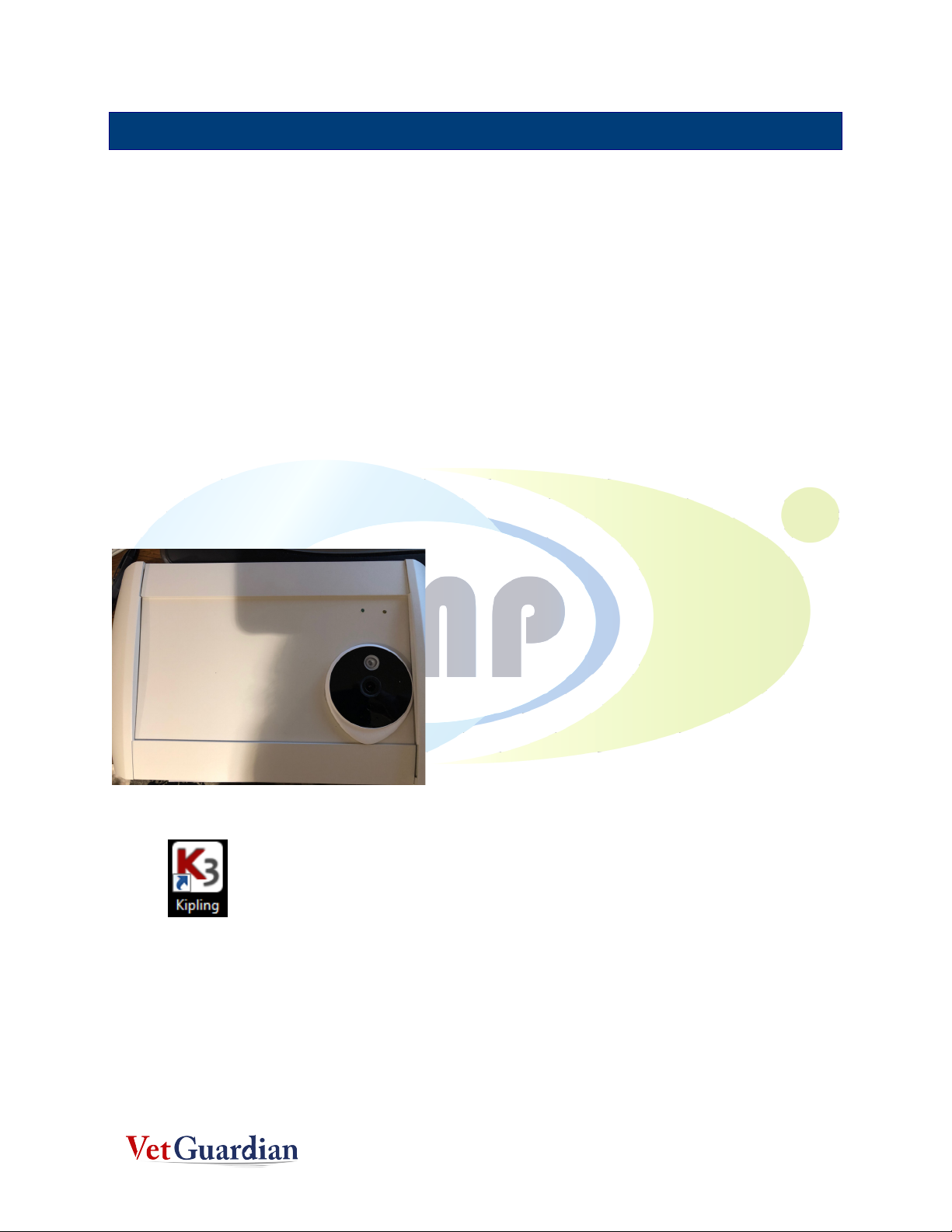
3. SETTING UP THE VETGUARDIAN
1. Unpack the contents of the box
2. The Device Arm is already connected to the Piranha-Lox® mount
3. Unpack the TP_Link ®Hotspot Router and plug it to the wall socket within the room. (Note:
The TP-Link DOES NOT connect to anything else).
4. Unpack VetGuardian (Contained in the smaller box) and mount the bottom of the device to the
Device Arm.
5.
Warning! The screw-insert of the VetGuardian is glued in. So be careful when you mount the
device to the arm. Any sudden movements, the screw insert may come off. Please mount it
until the flat portion on the arm is flush with the device base. Future models will have better
clamped screw-inserts.

7
6. Attach the Kennel Gear to a Cat cage
7. Mount the assembled VetGuardian along with the Device Arm and the Pirhana Lox on to the
Kennel Gear, with the VetGuardian outside the cage with the camera lens facing the animal.
8. Plug in the VetGuardian using the adapter provided in the box.
NOTE: The VETGUARDIAN power Adapter is in a small white box)
8
4. INSTALL DRIVER
4.1.RUNNING THE KIPLING PROGRAM
1. Install the Kipling Software driver.
oThe Kipling program contains the drivers and Kipling SW which can be used to test the
hardware connections.
2. Once the TP-Link is setup as an Access Point, Turn on VetGuardian
3. A Green LED Light indicates that the device is on
4. Wait for a few seconds and the Camera, the Yellow light, and the flashing blue light will
appear on the camera
5. On the Desktop, look for the Kipling Software
6. The Kipling software is initially used to connect to the LABJACK. (The LabJack is a device that
is inside the VetGuardian to transmit the raw signals to the laptop via the TP-Link)
9
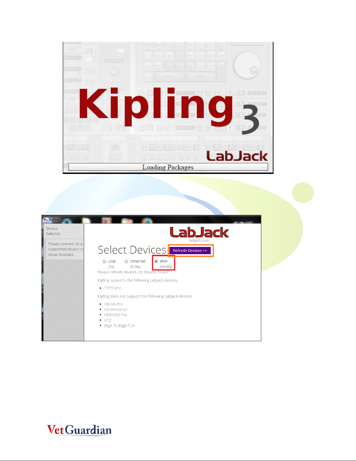
7. After the program loads, you may see the below page. Make sure the wifi is option checked
and then click on Refresh Devices
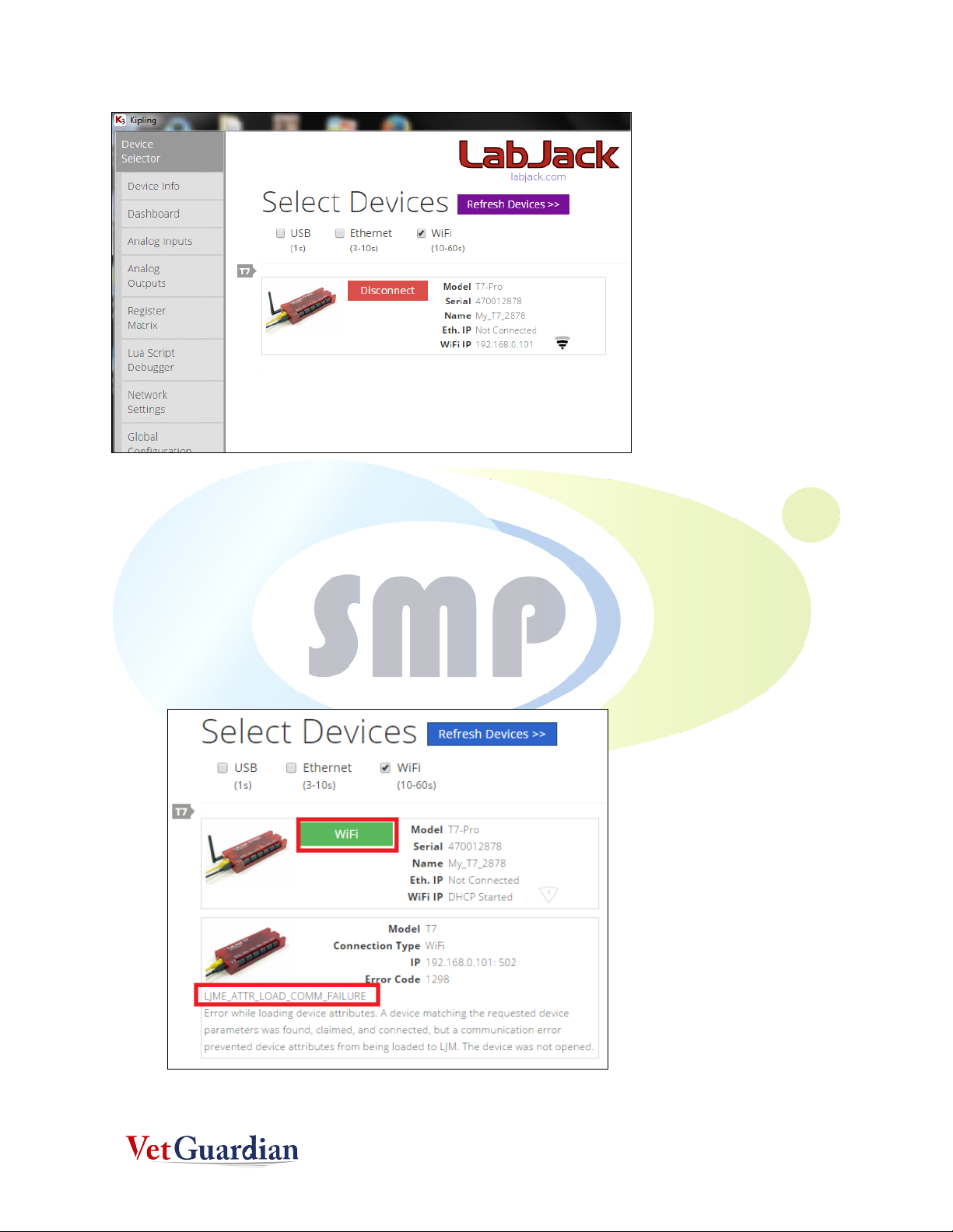
8. If the refresh is successful, you will see the screen below. (DO NOT CLICK ON THE
DISCONNECT BUTTON). If it's not successful, please keep refreshing as shown in step 6, until
you get the screen below. If it still does not work after a couple of tries, call 305-799-3075 for
support.
10
9. You will notice that an Yellow light also starts flickering on the VetGuardian
10. After this step, close the Kipling Software.
11. Some other errors you may encounter are shown below. In this case, click on the Green Wifi
Button and then Step 7 will be shown

11
5. VETGUARDIAN
5.1.INSTALL THE VETGUARDIAN SOFTWARE PER THE INSTALLER
FILE
Note: Registration may be required to run the program.
5.2.RUNNING THE VETGUARDIAN PROGRAM
1. WARNNG! DO NOT OPEN\RUN VETGUARDIAN SOFTWARE and the KIPLING test software. It
will cause the Wifi Connection to disconnect.
2. Make sure Kipling is closed
3. Open the VetGuardian application only after step 7 of Section 4.2 (running Kipling software) is
successful
4. Please make sure you click VG Application only once. Also note that it takes time to load the
application (at least 30 seconds). If you open more than one VG application, the wifi will fail
and you may get a message like this shown below. If this happens, close the message box and
try opening the VG application again.

12
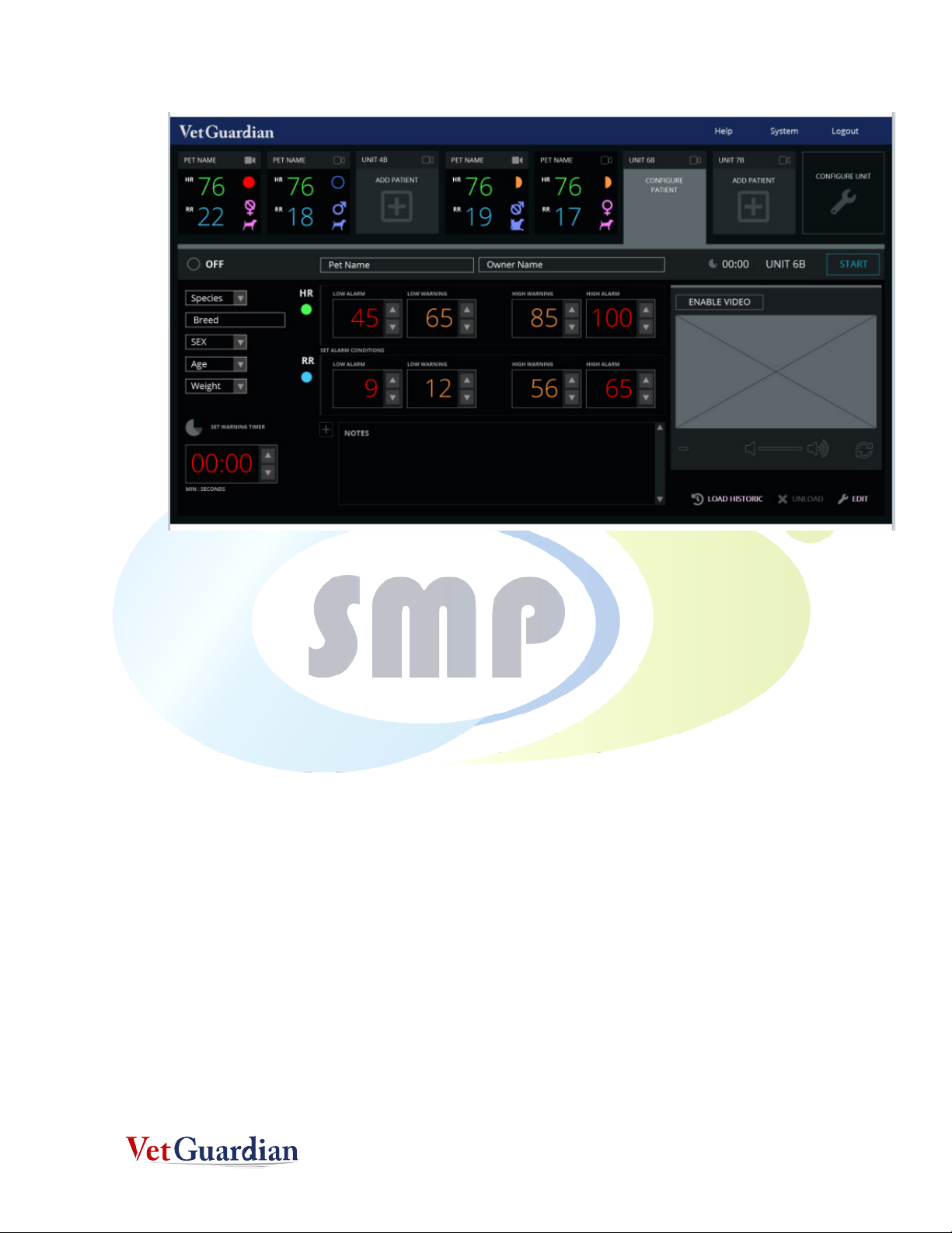
5. When the application opens up, you will be seeing the screen below.
6. Select Animal and then choose the animal to be monitored such as CAT or DOG ,etc
13
7. Then choose Setting Menu, select Calibrate (if needed).
8. Warning! Make sure the unit is pointing at an empty cage or any location where there is no
movement. Calibration is performed to differentiate between noise and signal. After
Calibration, The application understands that if there is no movement, it will assign 0 for RR
and HR.
9. Calibration Window open and after Calibration is completed, Click OK.
10. After the Calibration is completed, focus the device on the cat in the cage.
11. Enter the animals name and click on Start Monitoring
12. You will be now able to see HR and RR of the Subject

14
13. To complete Monitoring, click on Stop Monitoring.
oAfter stopping notes ,etc can be entered
14. To open the Saved animal file
15. Choose the file to open and view the saved HR and RR readings
16. To see the physical location of the files, open this Root Directory: C:\DataCapture. All Pictures
are saved at every minute and stored in this folder.

15
Table of contents


