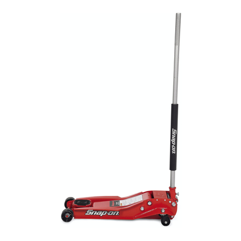
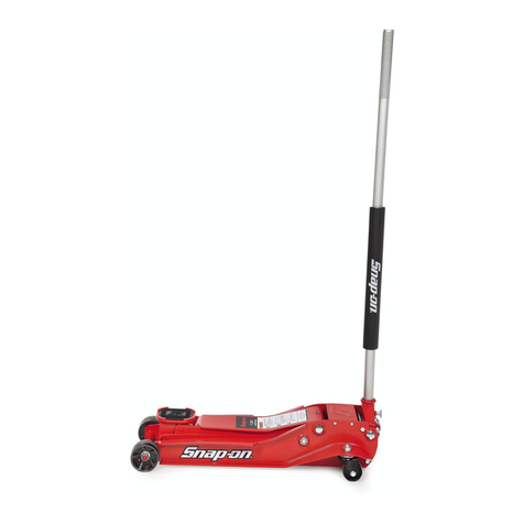
Snap-On FJ400 User manual

4 TON FLOOR JACK
FJ400
INTRODUCTION
The FJ400 4 Ton Floor Jack is an exclusive Snap-on® design which provides the
professional technician with quick performance, ideal lift heights and the dependable
service they require.
TECHNICAL SUPPORT AND SERVICE
US: 877-762-7664
CANADA: 866-824-0524

FJ400 2 Rev. 07/23/18
TABLE OF CONTENTS
Introduction ...................................................Front Cover
Table of Contents. . . . . . . . . . . . . . . . . . . . . . . . . . . . . . . . . . . . . . . . . . . . . . . . . . . . . . . .2
Safety Information .......................................................3
Specications ..........................................................4
Features ..............................................................5
Start-up Guide ..........................................................6
Operation..............................................................7
Maintenance .........................................................8-9
Troubleshooting........................................................10
Parts List .............................................................11
Warranty/Service and Repair .............................................12

FJ400 3 Rev. 07/23/18
SAFETY INFORMATION
MUST READ INSTRUCTIONS
BEFORE USE
• Improper use can result in vehicle falling or jack failure
Study, understand, and follow all instructions before operating this device.
Inspect the jack before each use.
Donotusejackifdamaged,alteredmodied,inpoorcondition,leaking
hydraulicuid,orunstableduetolooseormissingcomponents.Make
corrections before using.
Use this jack as a lifting device only.
Failure of jack or jack stands or falling of vehicle can caused serious injury or death.
• Jack may fail or allow vehicle to fall if used improperly
Do not attempt to lift more than the rated capacity of jack and jack stands.
Lift vehicle only on its designated lift points and centerload on saddle.
Do not move or dolly the vehicle when supported by the jack.
Do not use materials that may serve as risers, spacers or extenders between the
stock lifting saddle and the load.
Do not use adapters that replace the stock lifting saddle unless supplied by
Snap-on®.
Failure of jack or falling vehicle can cause property damage, serious injury
or death.
• Jack may allow vehicle to fall if additional support is not used while working on vehicle
Use jack and jack stands only on a hard level surface.
Do not work on vehicle supported only by the jack.
Use jack stands in pairs to support the vehicle immediately after lifting.
Falling vehicle can cause property damage, serious injury or death.
WARNING: This product can expose you to chemicals including nickel which is known to
the State of California to cause cancer and birth defects or other reproductive harm.
For more information go to www.P65Warnings.ca.gov.
SAVE THESE INSTRUCTIONS

FJ400 4 Rev. 07/23/18
SPECIFICATIONS
Specications FJ400
Capacity 4 Ton
Low Height (in.) 4.2
Max Lifting Height (in.) 24.5
Saddle size (in.) 5.1 x 5.1 sq.
Ground Clearance 0.75
Chassis Length (in.) 33.3
Overall Width @ Front wheels (in.) 11.5
Minimum Chassis Width (in.) 7.1
Overall Width @ Rear Casters (in.) 14.8
Handle Length to Floor (in. @90 ) 56.6
Handle Length (in.) 50.0
Front Wheel Diameter (in.) 3.94
Front Wheel Width (in.) 2.0
Axle Diameter (in.) 0.98
Caster Wheel Diameter (in.) 2.56
Saddle height, one pump, no load (in.) 8.5
Pump strokes to reach max lifting height, no load 6
Hydraulic Oil Snap-on®High-Performance
Weight (lbs.) 122.8
Shipping Weight (lbs.) 131.8

FJ400 5 Rev. 07/23/18
FEATURES
The Snap-on®FJ400 4 Ton Capacity Service
Jack was designed specically for the profession-
al technician. The Model FJ400 is assembled in
the USA and includes Patents and Patent Pend-
ing features that provide exceptional performance
and reliability.
CHASSIS
The exclusive Snap-on®jack chassis is made
of steel plate with re-enforcing upper and lower
anges for added strength. Low lift height and
extended low prole frame provide access under
low ground clearance vehicles. High lift height for
positioning vehicles on frame straightening racks
or alignment systems. Large patented saddle
for load positioning, locks into saddle base and
is easily removed for installation of other saddle
adapters.
HYDRAULIC POWER UNIT
The two pump piston power unit raises the jack’s
saddle to the load quickly to save work time. Once
a load is applied to the saddle, the jack will func-
tion normally and not lift the load with the fast
rise feature. Spring loaded pump pistons are in
constant contact with the handle yoke to prevent
handle from falling. An integrated ltration system
prohibits contaminants from entering hydraulic
valves and high pressure components. Self-con-
tained non-vented reservoir prevents uid leaks.
High performance seals and hydraulic uid pro-
vide longer life. Load-limiting and bypass valves
prevent use beyond working capacity and prevent
over-extension of the ram.
MANEUVERABILITY
Wide track front wheels with crowned rolling
surface and grease ttings provide smooth
rotation. Wheels secured to axles by way of
locknuts. Two rear swivel caster assemblies are
constructed with dual bearings and lubricated
axles for minimal axial and radial play.
SMOOTH OPERATION
Fully factory lubed with grease ttings in the lift
arm and two ttings in the handle yoke to access
pivot pins. Handle yoke includes quick-lock spring
knob for easy handle insertion or removal. Heavy
duty release valve assembly with built-in stop pre-
vents accidental removal and provides easy rota-
tion. Long one-piece handle for easier pumping
and positioning of jack under vehicle.
ADDITIONAL INFORMATION:
• Low height of 4.2" to t easily under a
variety of vehicles.
• Lift arm is contoured to allow clearance
with vehicle’s rocker panel.
• Maximum lifting height of 24.5".
• Dual pump pistons for speed to reach
service height quickly.
• Premium U-cup seals on pumps and ram
pistons for long life.
• Removable saddle with rubber pad.
• Professional, one-piece handle design.
• Grease ttings in lift arm pivot, handle yoke
pivot and front wheels.
• Front wheels have a nut and shoulder
design for positive retention.
•
Special Snap-on
®
high-performance
hydraulic
oil for extreme temperatures and
reduced wear.
• Internal ltration with magnet in pump
reservoir to maintain oil cleanliness.
• Powder coated nish for durability.

FJ400 6 Rev. 07/23/18
START-UP GUIDE
1. The handle yoke assembly FJ400-11 is
contained in a horizontal position for shipping
purposes by way of a retaining wire. In
order to remove the wire, push down on the yoke
with the heel of one hand while simultaneously
pinching the legs of the wire together with the
other hand. The yoke is under spring pressure
so be sure to ease hand pressure off the yoke
when the retaining wire is removed.
• Retaining wire may have sharp edges.
Wear gloves while performing
this step.
Sharp edges may cause personal injury.
2. Insert the grooved end of the handle with foam
pad FJ400-2 in the handle yoke assembly
FJ400-11 until the groove is engaged by the
pin of the handle yoke retaining assembly
FJ200-12. Pull up on the handle to make sure
the pin has engaged the handle groove.
Slightly rotate the handle clockwise and
counterclockwise to make sure the universal
joint assembly FJ400-3 movement corresponds
with the handle rotation.
3. Turn the handle FJ400-2 clockwise until
tight. Pump the handle from its vertical to
horizontal position in order to raise the jack’s
saddle FJ400-6 to maximum height. It
should take 6 full incremental pump strokes
(give or take 1/2 stroke) to raise the
saddle to maximum height without a
load. If the jack pumps to maximum height in
the required number of strokes the jack is ready
to use. Use the following procedure if the jack
does not go to maximum height without a
load in the number of required strokes:
a. Turn the handle counterclockwise two
full rotations from its closed position.
Proceed to pump the jack without a load
about 10 to 15 pump strokes. This will
force the air in the system into the power
unit’s reservoir.
b. Turn the handle in a clockwise rotation
until tight. Proceed to pump the handle
in full incremental pump strokes until
the saddle is raised to maximum height
without a load.
c. If the full incremental pump strokes still
exceed 6-1/2 pumps, repeat steps
a and b until all air is purged from
the system.

FJ400 7 Rev. 07/23/18
OPERATION
To Raise A Load
1. The vehicle transmission should be in “park” if
automatic or in gear if a standard shift. Apply
the emergency brake.
2. Check with the vehicle’s owner’s manual or
manufacturer for the proper lifting points.
3. Using the jack’s handle FJ400-2, maneuver the
jack so its saddle FJ400-6 is positioned right
below the vehicle’s designated lift point. Rotate
the jack’s handle FJ400-2 clockwise until it
stops.
4. Pump the jack slowly to ensure the saddle will
be aligned with the vehicle’s lift point. As the
saddle gets closer to the lift point, reposition the
jack so the saddle will contact the lift point
rmly and the load is centered on the saddle.
If the saddle and load are not properly aligned,
rotate the handle slowly in a counterclockwise
direction so the saddle is released from the
vehicle. Repeat step 4 until the saddle and
vehicle lift point are properly aligned.
• Jack may allow vehicle to fall if
additional support is not used while
working on vehicle
Use jack and jack stands only on
a hard level surface.
Do not work on vehicle
supported only by the jack.
Use jack stands in pairs to
support the vehicle immediately
after lifting.
Falling vehicle can cause property
damage, serious injury or death.
5. After the vehicle has been lifted to its desired
work height, place jack stands at the vehicle’s
designated support points and raise the jack
stand’s support columns as high as they will
go without touching the vehicle’s support
points. Make sure the stand’s support columns
are aligned with the vehicle’s support points
and the support points will not be resting on the
columns’ locating lugs.
6. After the jack stands have been properly
positioned and their columns adjusted to the
required height, rotate the jack’s handle
slowly counterclockwise to lower the vehicle on
the stands. Inspect the relationship between
the jack stands and vehicle support points to
make sure the setup is stable and safe. If the
setup is not stable and safe, follow the
preceding steps until corrected. If the setup is
safe, continue rotating the jack’s handle until its
saddle is lowered all the way down and remove
the jack from underneath the vehicle.
To Lower A Load
1. Follow steps 1 through 4 under To Raise
A Load above.
2. Slowly pump the jack until the vehicle lift points
are raised off and clear the jack stand’s
columns.
3. Remove the jack stands from under the vehicle
without crawling under the vehicle.
4. Rotate the jack’s handle slowly in a
counterclockwise direction to lower the vehicle.
Once the jack’s saddle has cleared the
vehicle’s lift point, remove the jack from
underneath the vehicle.

FJ400 8 Rev. 07/23/18
MAINTENANCE
To ensure that this jack maintains its operating
efciency, the following maintenance schedule
and procedures are required. These schedules
and procedures are the responsibility of the jack
owner.
REGULARLY - Usage and shop conditions
determine frequency.
1. Always store the jack in a well protected area
where it will not be exposed to inclement
weather, corrosive vapors, abrasive dust, or
any harmful elements. The jack must be
cleaned of water, snow, sand, grit, oil,
grease or other foreign matter
immediately after exposure.
2. Every jack owner is responsible for keeping
jack labels clean and readable. Cleaning can
be accomplished by using a mild soap solution
to wash external surfaces but not any moving
hydraulic components. Immediately after
cleaning dry the jack completely.
3. Inspect the jack before each work day. Do not
use the jack if any component is cracked,
broken, bent, shows sign of damage or leaks
hydraulic uid. Remove from service until
properly serviced or repaired.
4. Inspect the jack before each day for loose or
missing hardware or components. Take
corrective action before using. Premature
wearing or damage to any jack components
resulting from loose or missing hardware are
not eligible for warranty consideration.
WEEKLY
1. The jack must be lubricated with lithium base
grease (only) in order to prevent premature
wearing of parts and guarantee smooth
operation. A general purpose lithium base grease
must be used in the grease ttings provided in
both front wheels FJ400-4, lift arm assembly,
and two in the handle yoke assembly FJ400-11.
Additional areas of lubrication are found in
Figure 1. Worn parts resulting from the use of
improper grease, inadequate or no lubrication are
not eligible for warranty consideration.
a. Using a grease gun, add lithium base
grease to grease tting in the lift arm pivot
shaft, front wheels, and handle yoke.
b. Lubricate all linkages and pivot points.
(Use white lithium spray grease only.)
c. Remove handle; lubricate handle
receptacle and handle end. (Use white
lithium spray grease only.)
d. Lubricate both rear casters bearings (Use
white lithium spray grease only.)
Figure 1
#3
#3
#1
#2
#1
#2
#4
#1

FJ400 9 Rev. 07/23/18
MAINTENANCE
2. Check tightening of all hardware.
3.
Check rotation of front wheels and rear caster
wheels.
4. Use compressed air to remove any dust or
dirt from the jack.
TYPE OF OIL AND CORRECT OIL LEVEL
In the event the jack’s hydraulic reservoir
requires additional uid, use only a non-detergent
hydraulic jack oil with 22 viscosity rating. Using
any other uid will cause damage to the seals
and void the warranty.
In order to ensure proper performance, the
correct uid level must be maintained in the
reservoir.
Follow these steps to check for the correct
oil level:
1. Place the jack on a at level surface.
Remove the jack’s cover plate. The jack’s lift
arm should be all the way down. See Figure 3.
2. Rotate the handle in a counter-
clockwise direction from its closed
position and push the handle down so it is
parallel to the ground.
3. Remove the ll screw from the power unit’s
reservoir as shown in Figure 2. Look through
the ll screw hole in the reservoir to see that
the uid level is no higher than the top of the
cylinder inside the reservoir. It may be
necessary to add or remove uid accordingly.
4. Reinstall the ll screw and follow step 3 on page
6 of this manual to purge air out of the power
unit.
Figure 2
FILL SCREW
FLUID LEVEL RESERVOIR TUBE
CYLINDER
Figure 3
Scan codes
for more
Information

FJ400 10 Rev. 07/23/18
TROUBLESHOOTING
FOR TECH SERVICE, CALL USA: 877-762-7664, CANADA: 866-824-0524
PROBLEM POSSIBLE
CAUSE REMEDY
Jack will not lift or
sustain rated load.
A. Release valve is not
tightened down.
B. Air is trapped in the
hydraulic system.
C. Check ball valve is not
seating properly.
D. Load exceeds the rated
capacity of the jack.
A. Re-insert handle in handle
yoke making sure the
release valve is engaged
by the handle. Rotate
handle clockwise until it
stops. Proceed to pump.
B. Follow step 3 on page 6 of
this manual.
C. Call Tech Service.
D. Use the proper rated
capacity jack for the
application.
Jack will not lift to full
height.
A. Air is trapped in the
hydraulic system.
B. Not enough hydraulic
uid in reservoir.
A. Follow step 3 on page 6.
B. Remove reservoir ll plug.
Make sure uid level is
equal to top of the internal
cylinder with the lift arm
lowered all the way. See page 9.
Jack will not lower all the
way down without a load.
A. Too much uid in
reservoir.
B. Mechanical restriction
somewhere within the
chassis assembly.
C. Bent or deformed
chassis component.
A. Remove reservoir ll plug. Make
sure uid level is equal to top of
internal cylinder with lift arm and
handle lowered all the way.
See pg 9.
Remove excess uid if
above internal cylinder.
B. Follow step 1 under
WEEKLY Maintenance
section of this manual. See page 8.
C. Call Tech Service.
FILL SCREW
FLUID LEVEL RESERVOIR TUBE
CYLINDER

FJ400 11 Rev. 07/23/18
PARTS DRAWING AND PARTS LIST
Key Stock Number Description
01 FJ400-1
Rear Caster Assy, Spacer, Nut and Washer
02 FJ400-2 Handle w/Foam Pad
03 FJ400-3 Universal Joint w/Seal
04 FJ400-4 Front Wheel, Nut & Washers
05 FJ400-5 Power Unit Assembly - Complete
06 FJ400-6 Saddle
07 FJ300-7 Yoke Pump Roller Assembly
08 FJ400-8 Nut & Washers for Front Wheel
09 FJ400-9 Retaining Rings and Cotter Pin Set
10 FJ300-10 Return Springs (2)
11 FJ400-11 Handle Yoke Casting
Key Stock Number Description
12 FJ200-12 Handle Retaining Pin
13 FJ400-13 Foam Handle Pad
14 FJ200-14 Grease Fitting (5ea)
15 FJ200-15 Saddle Pad
16 FJ200-16 Yoke Pivot Bolts & Washers (2)
17 FJ200-17 Universal Joint Retainer & Screw
18 FJ400-18
Floor Jack and Handle Packaging (2)
19 FJ200-19 HPU Shipping Strap and Screw
(not shown)
20 FJ400-20 Truinon Block and Cotter Pin
21 FJ200-21 Cover plate screws - set of four
22 FJ400-22 Cover plate
15
6
9
4
14
1
16
10
5
17 3
14
11
16
14
13
10
8
12
9
2
8
8
7
3
9
9
20
22
21

FJ400 12 Rev. 07/23/18
WARRANTY/SERVICE AND REPAIR
Snap-on®Tools Limited Three (3) Year Warranty
Snap-on®Tools Company (the “Seller”) warrants only to original purchasers who use the Equipment in their
business that under normal use, care and service, the Equipment (except as otherwise provided herein) shall
be free from defects in material and workmanship for 3 years from the date of original invoice. Seller does not
provide any warranty for accessories used with the Equipment that are not manufactured by Seller.
SELLER’S OBLIGATIONS UNDER THIS WARRANTY ARE LIMITED SOLELY TO THE REPAIR OR, AT
SELLER’S OPTION, REPLACEMENT OF EQUIPMENT OR PARTS WHICH TO SELLER’S SATISFACTION
ARE DETERMINED TO BE DEFECTIVE AND WHICH ARE NECESSARY, IN SELLER’S JUDGMENT, TO
RETURN THIS EQUIPMENT TO GOOD OPERATING CONDITION. NO OTHER WARRANTIES, EXPRESS
OR IMPLIED OR STATUTORY, INCLUDING WITHOUT LIMITATION ANY IMPLIED WARRANTY OF MER-
CHANTABILITY OR FITNESS FOR A PARTICULAR PURPOSE, SHALL APPLY AND ALL SUCH WARRAN-
TIES ARE HEREBY EXPRESSLY DISCLAIMED.
SELLER SHALL NOT BE LIABLE FOR ANY INCIDENTAL, SPECIAL OR CONSEQUENTIAL COSTS OR
DAMAGES INCURRED BY PURCHASERS OR OTHERS (including, without limitations, lost prots, revenues,
and anticipated sales, business opportunities or goodwill, or interruption of business and any other injury or
damage).
This warranty does not cover (and separate charges for parts, labor and related expenses shall apply to) any
damage to, malfunctioning, in operability or improper operation of the Equipment caused by, resulting from
or attributable to (A) abuse, misuse or tampering; (B) alteration, modication or adjustment of the Equipment
by other than Seller’s authorized representatives; (e) installation, repair or maintenance (other than specied
other than Seller’s authorized representatives; (D) improper or negligent use, application, operation, care,
cleaning, storage or handling; (E) re, water wind, lightning or other natural causes; (F) adverse environmental
conditions, including, without limitation, excessive heat, moisture, corrosive elements, dust or other air con-
taminants, radio frequency interference, electric power failure, power line voltages beyond those specied for
the Equipment, unusual physical, electrical or electromagnetic stress and/or any other condition outside of
Seller’s environmental specications; (G) use of the Equipment in combination or connection with other equip-
ment, attachments, supplies or consumables not manufactured or supplied by Seller; or (H) failure to comply
with any applicable federal, state or local regulation, requirement or specication governing lifting equipment
and related supplies.
Repairs or replacements qualifying under this Warranty will be performed on regular business days
during Seller’s normal working hours within a reasonable time following purchaser’s request. All requests for
Warranty service must be made during the stated Warranty period. Proof of purchase date is required to make
a Warranty request. This Warranty is nontransferable.
Snap-on Tools, Kenosha, Wisconsin 53141-1410
Technical Support and Service US: 877-762-7664
Canada: 866-824-0524
Assembled and Tested in the USA. Product of China. Snap-on and Wrench “S” are trademarks of Snap-on Incorporated.
© Snap-on Incorporated 2018. All Rights Reserved. Patentes: visite https://patents.snapon.com
Snap-on 2801 80th St., Kenosha, WI 53143 www.snapon.com

GATO DE PISO 4 TONELADAS
FJ400
INTRODUCCIÓN
El gato de piso FJ400 de 4 toneladas es un diseño exclusivo de Snap-on® que le
brinda al técnico profesional un rendimiento rápido, alturas de elevación ideales y el
servicio conable el que ellos requieren.
SOPORTE Y SERVICIO TÉCNICO
US: 877-762-7664
CANADÁ: 866-824-0524

FJ400 14 Rev. 07/23/18
ÍNDICE DE CONTENIDOS
Introducción...........................................................13
Índice de contenidos ....................................................14
Información de seguridad ................................................15
Especicaciones .......................................................16
Características. . . . . . . . . . . . . . . . . . . . . . . . . . . . . . . . . . . . . . . . . . . . . . . . . . . . . . . . .17
Guía de arranque ......................................................18
Operación ............................................................19
Mantenimiento .....................................................20-21
Diagnóstico de averías ..................................................22
Lista de partes.........................................................23
Garantía/Servicio y reparaciones ..........................................24

FJ400 15 Rev. 07/23/18
INFORMACIÓN DE SEGURIDAD
INSTRUCCIONES OBLIGATORIAS
ANTES DEL USO
• El uso inadecuado podrá ocasionar la caída del vehículo o la falla de gato
Estudie, comprenda y siga todas las instrucciones antes de operar este dispositivo.
Inspeccione el gato antes de cada uso.
Nouseelgatosiestádañado,modicado,alterado,enpobrescondiciones,
si tiene fugas de líquido hidráulico, o si está inestable debido a componentes
ojosofaltantes.Asegúresederealizarlascorreccionesantesdeusarlo.
Use este gato como dispositivo de levantamiento solamente.
La falla del gato o de las bases del gato o la caída del vehículo podrá ocasionar lesiones serias o
aún la muerte
• El gato podría fallarse o permitir la caída del vehículo si se usara inadecuadamente.
No intente levantar más de la capacidad nominal del gato ni la de las bases del gato.
Levante el vehículo sólo en sus puntos designados y centre la carga en la silla.
No mueva ni use como plataforma rodante cuando esté soportado por el gato.
No use materiales los que puedan fungir como elevadores, separadores o expansores en
tre la silla de elevación estándar y la carga.
No use adaptadores los que repongan la silla de elevación estándar del fabricante al
menos que sea provisto por Snap-on®.
La falla del gato o la caída del vehículo podrá ocasionar daños a la propiedad, lesiones serias o
aún la muerte.
• El gato puede permitir la caída del vehículo si no se use soporte adicional al momento de
trabajar en el vehículo.
Use jack and jack stands only on a hard level surface.
Do not work on vehicle supported only by the jack.
Useelgatoylasbasesdelgatosobreunasuperciedurayniveladasolamente.
Notrabajesobrealgúnvehículosoportadosóloporelgato.
Use las bases del gato en pares para soportar el vehículo inmediatamente después del
levantamiento.
Un vehículo en caída podrá ocasionar daños, lesiones serias o aún la muerte
ADVERTENCIA: Este producto le podrá exponer a ciertos químicos, para incluir el níquel, conoci
dos en el Estado de California por ocasionar cáncer y defectos congénitos u otros daños a la
reproducción. Para mayores informes, visite: www.P65Warnings.ca.gov.
CONSERVE ESTAS INSTRUCCIONES

FJ400 16 Rev. 07/23/18
ESPECIFICACIONES
Especicaciones FJ400
Capacidad 4 toneladas
Altura baja (pulg.) 4.2
Máxima altura de levantamiento (pulg.) 24.5
Tamaño de la silla (pulg.) 5.1 x 5.1 cuad.
Despeje del piso 0.75
Largura del chasis (pulg.) 33.3
Anchura global en las ruedas delanteras (pulg.) 11.5
Mínima anchura de chasis (pulg.) 7.1
Anchura global en las rodajas posteriores (pulg.) 14.8
Largura del mango hasta el piso (pulg. a 90 ) 56.6
Largura del mango (pulg.) 50.0
Diámetro de la rueda delantera (pulg.) 3.94
Anchura de la rueda delantera (pulg.) 2.0
Diámetro del eje (pulg.) 0.98
Diámetro de la rueda de rodaja (pulg.) 2.56
Altura de la silla, un recorrido, sin carga (pulg.) 8.5
Recorridos de bomba para alcanzar la máxima
altura de levantamiento, sin carga
6
Aceite hidráulico Snap-on®Alto rendimiento
Peso (lbs.) 122.8
Peso de embarque (lbs.) 131.8

FJ400 17 Rev. 07/23/18
CARACTERÍSTICAS
El gato de servicio con 4 toneladas de capacidad
FJ400 de Snap-on® fue diseñado especícamente
para el técnico profesional. El modelo FJ400 se
ensambla en los E.U. e incluye las características
de patentes y patentes en trámite las que brindan
un rendimiento y conabilidad excepcionales.
CHASIS
El chasis del gato exclusivo de Snap-on®está
hecho de acero laminado con rebordes superi-
ores e inferiores reforzantes que agregan resis-
tencia adicional. La baja altura de levantamiento
y el armazón extendido de bajo perl brindan un
acceso debajo de los vehículos de bajo despeje
del piso. Alta altura de levantamiento para posicio-
nar los vehículos en los estantes de armazón de
enderezamiento o sistemas de alineación. Una
silla patentada grande para el posicionamiento de
carga se bloquea en la base de la silla y se extrae
fácilmente para la instalación de otros adaptado-
res de silla.
UNIDAD DE POTENCIA HIDRÁULICA
La unidad de potencia de dos bombas eleva la silla
del gato hasta la carga rápidamente para ahorrar
tiempo de trabajo. Una vez que se haya aplicado
una carga a la silla, el gato funcionará normal-
mente y no elevará la carga con la funcionalidad
de elevación rápida. Los pistones accionados por
resorte de la bomba están en constante contacto
con el mango de la abrazadera para prevenir la
caída del mango. Un sistema de ltración integrado
prohíbe que entren contaminantes a las válvulas
hidráulicas y a los componentes de alta presión. El
recipiente autosuciente sin ventilas previene las
fugas de líquidos. Los sellos de alto rendimiento y
líquido hidráulico brindan una vida útil más larga.
Las válvulas de limitación de carga y de paso pre-
vienen el uso más allá de la capacidad nominal de
trabajo y la sobre extensión del eje.
MANIOBRABILIDAD
Las ruedas delanteras de rodada ancha con super-
cie ondulada coronada y graseras brindan una ro-
tación suave. Las ruedas están sujetadas a los ejes
por medio de unas contratuercas. Dos ensambles
de rodaja giratoria trasera están construidas con
doble cojinete y ejes lubricados para una mínima
holgura axial y radial.
OPERACIÓN SUAVE
Lubricación plena de fábrica con graseras en el
brazo de levantamiento y dos acoplamientos en
la abrazadera del mango para tener acceso a los
pasadores de pivote. La abrazadera del mango in-
cluye una perilla accionada por resorte de bloqueo
rápido para facilitar la inserción y extracción. El
ensamble de la válvula de liberación para servicio
pesado con tope integrado previene la extracción
accidental y brinda una fácil rotación. Mango largo
de una sola pieza para el fácil bombeo y posiciona-
miento del gato debajo del vehículo.
INFORMACIÓN ADICIONAL:
• Baja altura de 4.2"para caber fácilmente
debajo de una variedad de vehículos.
• El brazo de levantamiento está contorneado
para proveer un despeje del estribo del
vehículo
• Máxima altura de levantamiento de 24.5".
• Pistones de doble bomba para una
velocidad que rápidamente alcance la altura
de servicio.
• Sellos acopados en forma de U y pistones
de calidad suprema para una vida útil larga.
• Silla desmontable con almohadilla de hule.
• Diseño de mango profesional de un sólo
mango.
• Graseras en el pivote del brazo de
levantamiento, pivote de la abrazadera del
mango y las ruedas delanteras.
• La ruedas delanteras cuentan con un
diseño de tuerca y hombro para la retención
positiva.
• Aceite hidráulico de alto rendimiento
especial de Snap-on®para las temperaturas
extremas y el degaste reducido.
• Filtración interna con imán en el recipiente
de la bomba con el n de mantener la
limpieza del aceite.
• Acabado de recubrimiento en polvo para
una mayor durabilidad.

FJ400 18 Rev. 07/23/18
GUÍA DE ARRANQUE
1. El ensamble del yugo del mango FJ400-11
se mantiene en una posición horizontal para los
propósitos de envío por medio de un alambre de
sujeción. Con el n de extraer el alambre, em-
puje hacia abajo sobre el yugo con la parte infe-
rior de la mano, mientras que simultáneamente
se pellizquen juntas las cuerdas del alambrado
con la otra mano. El yugo está bajo presión de
resorte, así que asegúrese de liberar la presión
lentamente sobre el yugo al momento de extraer
el alambre de sujeción.
• El alambre de sujeción podrá contar
con bordes losos.
Lleve puesto guantes durante la
realizacióndeestepaso.
Los bordes alados podrían ocasiones
lesiones personales.
2. Inserte el extremo ranurado del mango con la
almohadilla espumada FJ400-2 en el conjunto
de la abrazadera del mango FJ400-11 hasta
que la ranura se encaje por el pasador del
ensamble de la abrazadera del mango
FJ200-12. Jale hacia arriba en el mango para
asegurarse que el pasador se haya encajado
la ranura del mango. Gire el mango
ligeramente en el sentido de las agujas del
reloj y en el contrasentido de las agujas del
reloj con el n de asegurar que el movimiento
del ensamble de la junta universal FJ400-3
corresponda a la rotación del mango.
3. Gire el mango FJ400-2 en el sentido de las
agujas del reloj hasta que esté apretado.
Bombee el mango desde su posición vertical
hasta su posición horizontal con el n de elevar
la silla del gato FJ400-6 hasta su máxima
altura. Se requerirán 6 carreras de bomba i
crementales completas aproximadas (más o
menos una ½ carrera) para elevar la silla hasta
la máxima altura sin carga. Si el gato se bombee
hasta su máxima altura en el número de carreras
necesarias, entonces el gato está listo para us-
arse. Siga el procedimiento a continuación si el
gato no se eleva hasta su máxima altura sin carga
dentro del número de carreras necesarias:
a. Gire el mango en el contrasentido de las
agujas del reloj dos rotaciones completas
desde su posición cerrada. Proceda
a bombear el gato sin carga 10 a 15
recorridos aproximados. Lo mismo
forzará el aire en el sistema hasta entrar
al recipiente de la unidad de potencia.
b. Gire el mango en una rotación en el
sentido de las agujas del reloj hasta que
esté apretado. Proceda a bombear el
mango en recorridos incrementales
completos de la bomba hasta que se
eleve la silla hasta su máxima altura sin
carga.
c. Si las carreras incrementales completas
de la bomba aun excedan 6 ½ bombeos,
repita los pasos a y b hasta que se haya
purgado todo el aire del sistema.

FJ400 19 Rev. 07/23/18
OPERACIÓN
Para elevar una carga
1. La transmisión del gato deberá estar en
posición de “estacionado” si es una transmisión
automática, o en marcha puesta, si es de
cambios. Aplique el freno de mano.
2. Verique con el manual del propietario del
vehículo o con el fabricante los puntos de
levantamiento adecuados.
3. Usando el mango del gato FJ400-2, maniobre
el gato con el n de que la silla FJ400-6 esté
posicionada directamente debajo del punto
de levantamiento designado del vehículo. Gire
el mango del gato FJ400-2 en el sentido de las
agujas del reloj hasta que se pare.
4. Bombee el gato lentamente para asegurar que
la silla se alinee con el punto de levantamiento
del vehículo. En la medida que la silla se
acerque al punto de levantamiento, reposicione
el gato para que el gato tenga contacto rme
con el punto de levantamiento y la carga esté
centrada en la silla. Si la silla y la carga no
están alineadas adecuadamente, gire el ma
go lentamente en el contrasentido de las
agujas del reloj para que la silla se libere del
vehículo. Repita el paso 4 hasta que la silla y
el punto de levantamiento del vehículo estén
adecuadamente alineados.
• El gato puede permitir la caída del
vehículo si no se use algún soporte
adicional mientras que se está
trabajando en el vehículo.
Use el gato y las bases del gato sobre
una supercie dura y nivelada
solamente. No trabaje sobre algún
vehículo soportado sólo por el
gato. Inmediatamente después del
levantamiento,uselasbases delgato
en pares para soportar el vehículo.
Un vehículo en caída podrá
ocasionar daños a la propiedad,
lesiones serias o aún la muerte.
5. Después de que se haya elevado el vehículo
hasta su altura deseada de trabajo, coloque las
bases del gato en los puntos de soporte
designados y eleve las columnas de soporte
de la base del gato lo más alto que se pueda
sin que éstas toquen los puntos de soporte del
vehículo. Asegúrese que las columnas de
soporte de la base estén alineadas con los
puntos de soporte del vehículo y que los puntos
de soporte no recarguen sobre las muescas
de posicionamiento de las columnas.
6. Después de que las bases del gato se hayan
posicionado adecuadamente y que sus clumnas
hayan sido ajustadas hasta la altura requerida,
gire el mango del gato lentamente en el
contrasentido de las agujas del reloj para
bajar el vehículo sobre las bases. Inspeccione
la relación entre las bases del gato y los
puntos de soporte del vehículo para asegurar
que el montaje esté estale y seguro. Si el
montaje no está estable ni seguro, siga los
pasos anteriores hasta que esté corregido. Si
el montaje es seguro, siga girando el mango
del gato hasta que su silla se haya bajado
completamente hacia abajo y extraiga el gato
de debajo del vehículo.
Para bajar una carga
1. Siga los pasos 1 al 4 anteriores bajo Para Elevar
una Carga.
2. Bombee el gato lentamente hasta que los
puntos de levantamiento del vehículo se eleven
de y se despejen las columnas de la base del
gato.
3. Extraiga las bases del gato de debajo del
vehículo sin arrastrarse debajo del vehículo.
4. Gire el mango del gato lentamente en el
contrasentido de las agujas del reloj para bajar el
vehículo. Un vez que el gato haya despejado
el punto de levantamiento del vehículo, extraiga
el gato de debajo del vehículo.

FJ400 20 Rev. 07/23/18
MANTENIMIENTO
Para asegurarse que este gato mantenga su
eciencia de operación, son necesarios los
siguientes procedimientos y horario de
mantenimiento. Dichos horarios y procedimientos
son la responsabilidad del propietario del gato.
FRECUENTEMENTE - El uso y las
condiciones del taller determinarán la frecuencia.
1. Siempre almacene el gato en un área bien
protegida donde no estará expuesto a las
inclemencias del clima, vapores corrosivos,
polvo abrasivo ni cualquier otro elemento
dañino. El gato deberá estar limpio de agua,
nieve, arena, arenilla, aceite, grasa y otro
material foráneo inmediatamente después de
la exposición al mismo.
2. Cada propietario del gato será responsable
por mantener limpias y legibles las etiquetas
del gato. La limpieza puede lograrse al usar
una solución de jabón suave para lavar las
supercies externas pero sin mover ningún
componente hidráulico. Inmediatamente
después de la limpieza, seque el gato
completamente.
3. Inspeccione el gato antes de cada día de
trabajo. No use el gato si cualquier
componente esté agrietado, doblado, si
demuestre indicaciones de daños o si haya
fugas de líquido hidráulico. Deje de usarlo
hasta que el gato reciba mantenimiento o las
reparaciones adecuadas.
4. Inspeccione el gato antes de cada día de
trabajo por ferretería o componentes ojos o
faltantes. Tome acciones correctivas antes de
usarse. El desgaste prematuro o daños a
cualquier componente del gato ocasionado
por ferretería oja o faltante no son elegibles
para las consideraciones de garantía.
SEMANALMENTE
1. El gato debe lubricarse con una grasa a base
de litio (solamente) con el n de prevenir el
desgaste prematuro de las partes, así como
garantizar una operación suave. Una grasa de
uso general y a base de litio debe usarse en
las graseras provistas en ambas ruedas de
anteras FJ400-4, el ensamble del brazo de
levantamiento y dos en el ensamble de la
abrazadera del mango FJ400-11.
Las áreas adicionales de lubricación se
encuentran en la gura 1. Las partes
desgastadas ocasionadas por el uso de una
grasa inadecuada, una lubricación inadecu
da o faltante no son elegibles para las
consideraciones de garantía.
a. Usando una pistola lubricante, agregue
una grasa a base de litio a la grasera en
el eje de pivote del brazo de
levantamiento, ruedas delanteras y la
abrazadera del mango.
Figura 1
#3
#3
#1
#2
#1
#2
#4
#1
Table of contents
Languages:
Other Snap-On Jack manuals
Popular Jack manuals by other brands

Berger & Schroter
Berger & Schroter 31173 manual

King Tony
King Tony 9TY132 Series Operation manual

Napa
Napa 791-5280 Operating manual & parts list

Origen RV Accessories
Origen RV Accessories SnapPad Prime installation instructions

HWH
HWH 100 Series Operator's manual

Urrea
Urrea 260A User manual and warranty

Westward
Westward 1MZK9 Operating instructions & parts manual

Arcan
Arcan XL35R owner's manual

NEO TOOLS
NEO TOOLS 11-730 instruction manual

Cattini Oleopneumatica
Cattini Oleopneumatica YAK 300 Operating and maintenance manual

Branick
Branick 8700 Series Installation, Operation & Repair Parts Information

Weber UK
Weber UK 25-1 user guide