Snap-On FJ200 User manual

2 TON FLOOR JACK
FJ200
INTRODUCTION
The FJ200 2 Ton Floor Jack is an exclusive Snap-on design which provides the pro-
fessional technician with quick performance, ideal lift heights and the dependable
service they require.
TECHNICAL SUPPORT AND SERVICE
US: 877-762-7664
CANADA: 866-824-0524

FJ200 2 Rev. 09/09/14
TABLE OF CONTENTS
Introduction ...................................................Front Cover
Table of Contents. . . . . . . . . . . . . . . . . . . . . . . . . . . . . . . . . . . . . . . . . . . . . . . . . . . . . . . .2
Safety Information .......................................................3
Specications ..........................................................4
Features ..............................................................5
Start-up Guide ..........................................................6
Operation..............................................................7
Maintenance .........................................................8-9
Troubleshooting........................................................10
Parts List .............................................................11
Warranty/Service and Repair .............................................12

FJ200 3 Rev. 09/09/14
SAFETY INFORMATION
MUST READ INSTRUCTIONS
BEFORE USE
• Improperusecanresultinvehiclefallingorjackfailure
Study, understand, and follow all instructions before operating this device.
Inspect the jack before each use.
Donotusejackifdamaged,alteredmodied,inpoorcondition,leaking
hydraulicuid,orunstableduetolooseormissingcomponents.Make
corrections before using.
Use this jack as a lifting device only.
Failure of jack or jack stands or falling of vehicle can caused serious injury or death.
• Jackmayfailorallowvehicletofallifusedimproperly
Do not attempt to lift more than the rated capacity of jack and jack stands.
Lift vehicle only on its designated lift points and centerload on saddle.
Do not move or dolly the vehicle when supported by the jack.
Do not use materials that may serve as risers, spacers or extenders between the
stock lifting saddle and the load.
Do not use adapters that replace the stock lifting saddle unless supplied by
Snap-on.
Failure of jack or falling vehicle can cause property damage, serious injury
or death.
• Jackmayallowvehicletofallifadditionalsupportisnotusedwhileworkingonvehicle
Use jack and jack stands only on a hard level surface.
Do not work on vehicle supported only by the jack.
Use jack stands in pairs to support the vehicle immediately after lifting.
Falling vehicle can cause property damage, serious injury or death.
This product contains chemicals known to the state of California to cause cancer or birth defects or other
reproductive harm. Wash hands thoroughly after handling.
SAVE THESE INSTRUCTIONS

FJ200 4 Rev. 09/09/14
SPECIFICATIONS
Specications FJ200
Capacity 2 Ton
Low Height (in.) 3.5
Max Lifting Height (in.) 23.34
Saddle size (in.) 5.1 x 5.1 sq.
Ground Clearance 0.562
Chassis Length (in.) 30.75
Overall Width @ Front wheels (in.) 11.25
Minimum Chassis Width (in.) 7.06
Overall Width @ Rear Casters (in.) 14.56
Handle Length to Floor (in. @90 ) 56.13
Handle Length (in.) 50.0
Front Wheel Diameter (in.) 3.21
Front Wheel Width (in.) 2.0
Axle Diameter (in.) 0.78
Caster Wheel Diameter (in.) 2.34
Saddle height, one pump, no load (in.) 10.69
Pump strokes to reach max lifting height, no load 4
Hydraulic Oil Snap-on®High-Performance
Weight (lbs.) 101.0
Shipping Weight (lbs.) 103.5

FJ200 5 Rev. 09/09/14
FEATURES
The Snap-on®FJ200 2 Ton Capacity Service
Jackwasdesignedspecicallyfortheprofession-
al technician. The Model FJ200 is assembled in
the USA and includes Patents and Patent Pend-
ing features that provide exceptional performance
and reliability.
CHASSIS
The exclusive Snap-on jack chassis is made of
steel plate with re-enforcing upper and lower
anges for added strength. Low lift height and
extendedlowproleframeprovideaccessunder
low ground clearance vehicles. High lift height for
positioning vehicles on frame straightening racks
or alignment systems. Large patented saddle
for load positioning, locks into saddle base and
is easily removed for installation of other saddle
adapters.
HYDRAULIC POWER UNIT
Thetwopumppistonpowerunitraisesthejack’s
saddle to the load quickly to save work time. Spring
loaded pump pistons are in constant contact with
the handle yoke to prevent handle from falling. An
integratedltrationsystemprohibitscontaminants
from entering hydraulic valves and high pressure
components. Self-contained non-vented reservoir
preventsuidleaks.Highperformancesealsand
hydraulic uid provide longer life. Load-limiting
and bypass valves prevent use beyond working
capacity and prevent over-extension of the ram.
MANEUVERABILITY
Wide track front wheels with crowned rolling
surface and grease ttings provide smooth
rotation. Wheels secured to axles by way of
locknuts. Two rear swivel caster assemblies are
constructed with dual bearings and lubricated
axles for minimal axial and radial play.
SMOOTH OPERATION
Fully factory lubed with grease ttings in the lift
armandtwottingsinthehandleyoketoaccess
pivot pins. Handle yoke includes quick-lock spring
knob for easy handle insertion or removal. Heavy
duty release valve assembly with built-in stop pre-
vents accidental removal and provides easy rota-
tion. Long one-piece handle for easier pumping
andpositioningofjackundervehicle.
ADDITIONAL INFORMATION:
• Low height of 3.5" to t easily under a
variety of vehicles.
• Liftarmiscontouredtoallowclearance
withvehicle’srockerpanel.
• Maximumliftingheightof23.34".
• Dual pump pistons for speed to reach
service height quickly.
• Premium U-cup seals on pumps and ram
pistons for long life.
• Removablesaddlewithrubberpad.
• Professional,one-piecehandledesign.
• Greasettingsinliftarmpivot,handleyoke
pivot and front wheels.
• Front wheels have a nut and shoulder
design for positive retention.
•
Special Snap-on high-performance hydraulic
oil for extreme temperatures and reduced
wear.
• Internal ltration with magnet in pump
reservoir to maintain oil cleanliness.
• Powdercoatednishfordurability.

FJ200 6 Rev. 09/09/14
START-UP GUIDE
1. The handle yoke assembly FJ200-11 is
contained in a horizontal position for shipping
purposes by way of a wire clip. In order to
remove the wire clip, push down on the yoke
with the heel of one hand while simultaneously
disconnecting the clip legs from the lower
spacer bar with the other hand. The yoke is
under spring pressure so be sure to ease hand
pressure off the yoke when the clip legs are
disconnected.
2. Insert the grooved end of the handle with foam
pad FJ200-2 in the handle yoke assembly
FJ200-11 until the groove is engaged by the
pin of the handle yoke retaining assembly
FJ200-12. Pull up on the handle to make sure
the pin has engaged the handle groove.
Slightly rotate the handle clockwise and
counterclockwise to make sure the universal
jointassemblyFJ200-3movementcorresponds
with the handle rotation.
3. Turn the handle FJ200-2 clockwise until
tight. Proceed to activate the handle in full
incremental pump strokes in order to raise the
jack’s saddle FJ200-6 to maximum height. It
should take four full incremental pump
strokes (give or take a half a pump) to raise
the saddle to maximum height without a
load. If ve or more full incremental pumps
are required, there is air trapped in the power
unit assembly FJ200-5. Follow this procedure
to remove the air from the system:
a. Turn the handle counterclockwise two
full rotations from its closed position.
Proceedtopumpthejackwithoutaload
about 10 to 15 pump strokes. This will
force the air in the system into the power
unit’sreservoir.
b. Turn the handle in a clockwise rotation
until tight. Proceed to pump the handle
in full incremental pump strokes until
the saddle is raised to maximum height
without a load.
c. If the full incremental pump strokes still
exceed four and one half pumps, repeat
steps a and b until all air is purged from
the system.

FJ200 7 Rev. 09/09/14
OPERATION
To Raise A Load
1. The vehicle transmission should be in “park” if
automatic or in gear if a standard shift. Apply
the emergency brake.
2. Check with the vehicle’s owner’s manual or
manufacturer for the proper lifting points.
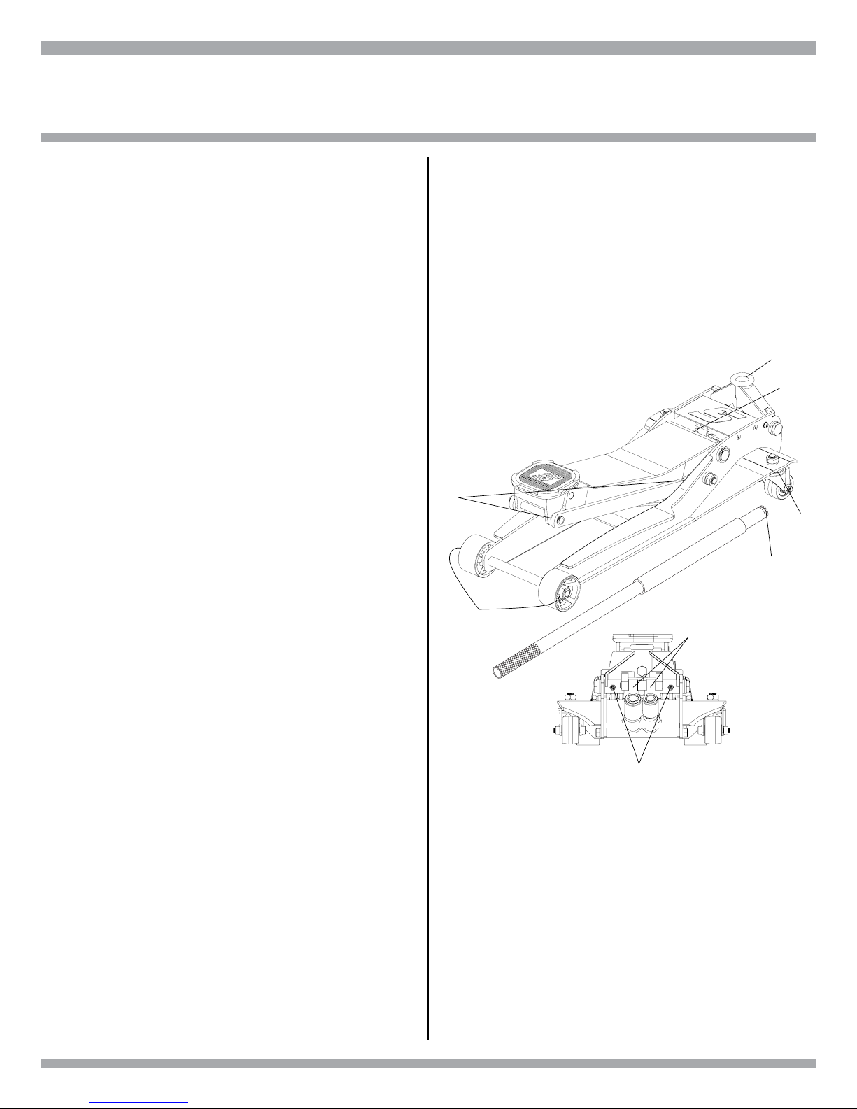
3.Usingthejack’shandleFJ200-2,maneuverthe
jack so its saddle FJ200-6 is positioned right
belowthevehicle’sdesignatedliftpoint.Rotate
the jack’s handle FJ200-2 clockwise until it
stops.
4.Pumpthejackslowlytoensurethesaddlewill
bealignedwiththevehicle’slift point.Asthe
saddle gets closer to the lift point, reposition the
jack so the saddle will contact the lift point
rmlyandtheloadiscenteredonthesaddle.
If the saddle and load are not properly aligned,
rotate the handle slowly in a counterclockwise
direction so the saddle is released from the
vehicle. Repeat step 4 until the saddle and
vehicle lift point are properly aligned.
• Jack may allow vehicle to fall if
additional support is not used while
working on vehicle
Use jack and jack stands only on
a hard level surface.
Do not work on vehicle
supported only by the jack.
Use jack stands in pairs to
support the vehicle immediately
after lifting.
Falling vehicle can cause property
damage, serious injury or death.
5. After the vehicle has been lifted to its desired
workheight,placejackstandsatthevehicle’s
designated support points and raise the jack
stand’s support columns as high as they will
go without touching the vehicle’s support
points.Makesurethestand’ssupportcolumns
are aligned with the vehicle’s support points
and the support points will not be resting on the
columns’locatinglugs.
6. After the jack stands have been properly
positioned and their columns adjusted to the
required height, rotate the jack’s handle
slowly counterclockwise to lower the vehicle on
the stands. Inspect the relationship between
thejackstands and vehicle support pointsto
make sure the setup is stable and safe. If the
setup is not stable and safe, follow the
preceding steps until corrected. If the setup is
safe,continuerotatingthejack’shandleuntilits
saddle is lowered all the way down and remove
thejackfromunderneaththevehicle.
To Lower A Load
1. Follow steps 1 through 4 under To Raise
A Load above.
2.Slowlypumpthejackuntilthevehicleliftpoints
are raised off and clear the jack stand’s
columns.
3.Removethejackstandsfromunderthevehicle
without crawling under the vehicle.
4.Rotate the jack’s handle slowly in a
counterclockwise direction to lower the vehicle.
Once the jack’s saddle has cleared the
vehicle’s lift point, remove the jack from
underneath the vehicle.

FJ200 8 Rev. 09/09/14
MAINTENANCE
To ensure that this jack maintains its operating
efciency, the following maintenance schedule
and procedures are required. These schedules
andproceduresaretheresponsibilityofthejack
owner.
REGULARLY - Usage and shop conditions
determine frequency.
1. Alwaysstorethejackinawellprotectedarea
where it will not be exposed to inclement
weather, corrosive vapors, abrasive dust, or
any harmful elements. The jack must be
cleaned of water, snow, sand, grit, oil,
grease or other foreign matter
immediately after exposure.
2. Every jack owner is responsible for keeping
jacklabelscleanandreadable.Cleaningcan
be accomplished by using a mild soap solution
to wash external surfaces but not any moving
hydraulic components. Immediately after
cleaningdrythejackcompletely.
3. Inspectthejackbeforeeachworkday.Donot
use the jack if any component is cracked,
broken, bent, shows sign of damage or leaks
hydraulic uid. Remove from service until
properly serviced or repaired.
4. Inspectthejackbeforeeachdayforlooseor
missing hardware or components. Take
corrective action before using. Premature
wearingor damageto anyjack components
resulting from loose or missing hardware are
not eligible for warranty consideration.
WEEKLY
1. Thejackmustbelubricatedwithlithiumbase
grease (only) in order to prevent premature
wearing of parts and guarantee smooth
operation. A general purpose lithium base grease
must be used in the grease ttings provided in
both front wheels FJ200-4, lift arm assembly,
and two in the handle yoke assembly FG200-11.
Additional areas of lubrication are found in
Figure 1. Worn parts resulting from the use of
improper grease, inadequate or no lubrication are
not eligible for warranty consideration.
a. Using a grease gun, add lithium base
greasetogreasettingintheliftarmpivot
shaft, front wheels, and handle yoke.
b. Lubricate all linkages and pivot points.
(Use white lithium spray grease only.)
c. Remove handle; lubricate handle
receptacle and handle end. (Use white
lithium spray grease only.)
d. Lubricate both rear casters bearings (Use
white lithium spray grease only.)
Figure 1
#3
#3
#1
#2
#1
#2
#4
#1

FJ200 9 Rev. 09/09/14
MAINTENANCE
2. Check tightening of all hardware.
3.
Check rotation of front wheels and rear caster
wheels.
4. Use compressed air to remove any dust or
dirtfromthejack.
TYPE OF OIL
In the event the jack’s hydraulic reservoir
requiresadditionaluid,useonlyanon-detergent
hydraulic jack oil with 22 viscosity rating. Using
any other uid will cause damage to the seals
and void the warranty. In order to ensure proper
performance, the correct uid level must be
maintainedinthereservoir.Theproperuidlevel
ischeckedwhenthejack’sliftarmisalltheway
down.Theuidlevelshouldbenohigherthanthe
top of the internal cylinder as shown in Figure 2.
Figure 2
FILL SCREW
FLUID LEVEL RESERVOIR TUBE
CYLINDER

FJ200 10 Rev. 09/09/14
TROUBLESHOOTING
FOR TECH SERVICE, CALL USA: 877-762-7664, CANADA: 866-824-0524
PROBLEM POSSIBLE
CAUSE REMEDY
Jack will not lift or
sustain rated load.
A. Release valve is not
tightened down.
B. Air is trapped in the
hydraulic system.
C. Check ball valve is not
seating properly.
D. Load exceeds the rated
capacityofthejack.
A. Re-insert handle in handle
yoke making sure the
release valve is engaged
by the handle. Rotate
handle clockwise until it
stops. Proceed to pump.
B. Follow step 3 on page 6 of
this manual.
C. Call Tech Service.
D. Use the proper rated
capacityjackforthe
application.
Jack will not lift to full
height.
A. Air is trapped in the
hydraulic system.
B. Not enough hydraulic
uidinreservoir.
A. Follow step 3 on page 6.
B.Removereservoirllplug.
Makesureuidlevelis
equal to top of the internal
cylinder with the lift arm
lowered all the way. See page 9.
Jack will not lower all the
way down without a load.
A.Toomuchuidin
reservoir.
B. Mechanical restriction
somewhere within the
chassis assembly.
C. Bent or deformed
chassis component.
A.Removereservoirllplug.Make
sureuidlevelisequaltotopof
internal cylinder with lift arm
lowered all the way. See page 9.
Removeexcessuidif
above internal cylinder.
B. Follow step 1 under
WEEKLY Maintenance
section of this manual. See page 8.
C. Call Tech Service.
FILL SCREW
FLUID LEVEL RESERVOIR TUBE
CYLINDER

FJ200 11 Rev. 09/09/14
PARTS DRAWING AND PARTS LIST
Key Stock Number Description
01 FJ200-1 Rear Caster Assy, Nut and Washer
02 FJ200-2 Handle w/Foam Pad
03 FJ200-3 Universal Joint w/Seal
04 FJ200-4 Front Wheel, Nut & Washers
05 FJ200-5 Power Unit Assembly - Complete
06 FJ200-6 Saddle
07 FJ200-7 Yoke Pump Roller Assembly
08 FJ200-8 Nut & Washers for Front Wheel
09 FJ200-9 Retaining Rings and Cotter Pin Set
Key Stock Number Description
10 FJ200-10 Return Springs (2)
11 FJ200-11 Handle Yoke Casting
12 FJ200-12 Handle Retaining Pin
13 FJ200-13 Foam Handle Pad
14 FJ200-14 Grease Fitting (5ea)
15 FJ200-15 Saddle Pad
16 FJ200-16 Yoke Pivot Bolts & Washers (2)
17 FJ200-17 Universal Joint Retainer & Screw
18 FJ200-18
Floor Jack and Handle Packaging (2)

FJ200 12 Rev. 09/09/14
WARRANTY/SERVICE AND REPAIR
Snap-on®Tools Limited Three (3) Year Warranty
Snap-onTools Company (the “Seller”) warrants only to original purchasers who use the Equipment in their
business that under normal use, care and service, the Equipment (except as otherwise provided herein) shall
be free from defects in material and workmanship for 3 years from the date of original invoice. Seller does not
provide any warranty for accessories used with the Equipment that are not manufactured by Seller.
SELLER’S OBLIGATIONS UNDER THIS WARRANTY ARE LIMITED SOLELY TO THE REPAIR OR, AT
SELLER’SOPTION,REPLACEMENTOFEQUIPMENTORPARTSWHICHTOSELLER’SSATISFACTION
AREDETERMINEDTOBEDEFECTIVEANDWHICHARENECESSARY,INSELLER’SJUDGMENT,TO
RETURNTHISEQUIPMENTTOGOODOPERATINGCONDITION.NOOTHERWARRANTIES,EXPRESS
OR IMPLIED OR STATUTORY, INCLUDING WITHOUT LIMITATION ANY IMPLIED WARRANTY OF MER-
CHANTABILITY OR FITNESS FOR A PARTICULAR PURPOSE, SHALL APPLY AND ALL SUCH WARRAN-
TIESAREHEREBYEXPRESSLYDISCLAIMED.
SELLER SHALL NOT BE LIABLE FORANY INCIDENTAL, SPECIAL OR CONSEQUENTIAL COSTS OR
DAMAGESINCURREDBYPURCHASERSOROTHERS(including,withoutlimitations,lostprots,revenues,
andanticipatedsales,businessopportunitiesorgoodwill,orinterruptionofbusinessandanyotherinjuryor
damage).
This warranty does not cover (and separate charges for parts, labor and related expenses shall apply to) any
damage to, malfunctioning, in operability or improper operation of the Equipment caused by, resulting from
orattributableto(A)abuse,misuseortampering;(B)alteration,modicationoradjustmentoftheEquipment
byotherthanSeller’sauthorizedrepresentatives;(e)installation,repairormaintenance(otherthanspecied
other than Seller’s authorized representatives; (D) improper or negligent use, application, operation, care,
cleaning,storageorhandling;(E)re,waterwind,lightningorothernaturalcauses;(F)adverseenvironmental
conditions, including, without limitation, excessive heat, moisture, corrosive elements, dust or other air con-
taminants,radiofrequencyinterference,electricpowerfailure,powerlinevoltagesbeyondthosespeciedfor
the Equipment, unusual physical, electrical or electromagnetic stress and/or any other condition outside of
Seller’senvironmentalspecications;(G)useoftheEquipmentincombinationorconnectionwithotherequip-
ment, attachments, supplies or consumables not manufactured or supplied by Seller; or (H) failure to comply
withanyapplicablefederal,stateorlocalregulation,requirementorspecicationgoverningliftingequipment
and related supplies.
Repairs or replacements qualifying under this Warranty will be performed on regular business days
duringSeller’snormalworkinghourswithinareasonabletimefollowingpurchaser’srequest.Allrequestsfor
Warranty service must be made during the stated Warranty period. Proof of purchase date is required to make
a Warranty request. This Warranty is nontransferable.
Snap-on Tools, Kenosha, Wisconsin 53141-1410
Technical Support and Service US: 877-762-7664
Canada: 866-824-0524
Assembled and Tested in the USA. Snap-on and Wrench “S” are trademarks of Snap-on Incorporated.
© Snap-on Incorporated 2014. All Rights Reserved.
Snap-on 2801 80th St., Kenosha, WI 53143 www.snapon.com
Table of contents
Other Snap-On Jack manuals
Popular Jack manuals by other brands

Duff-Norton
Duff-Norton 528AMJ Operating and Maintenance Instructions with Parts

Sealey
Sealey 300ETJ instructions

AC Hydraulic
AC Hydraulic 25-1 user guide

Borum
Borum BTJ35TA owner's manual

Tronair
Tronair 02-7813C0100 Operation & service manual

K Tool International
K Tool International KTI63515 owner's manual

Sealey
Sealey TSJ10 instructions

Clarke
Clarke Strong-Arm CTJ100 Operating & maintenance instructions

Torin BIG RED
Torin BIG RED TH932001B owner's manual

Mega
Mega N10-3 Operation and maintenance instructions

SFA
SFA Platinum Series Operating instructions & parts manual

Rescue 42
Rescue 42 TeleCrib Strut Jack manual