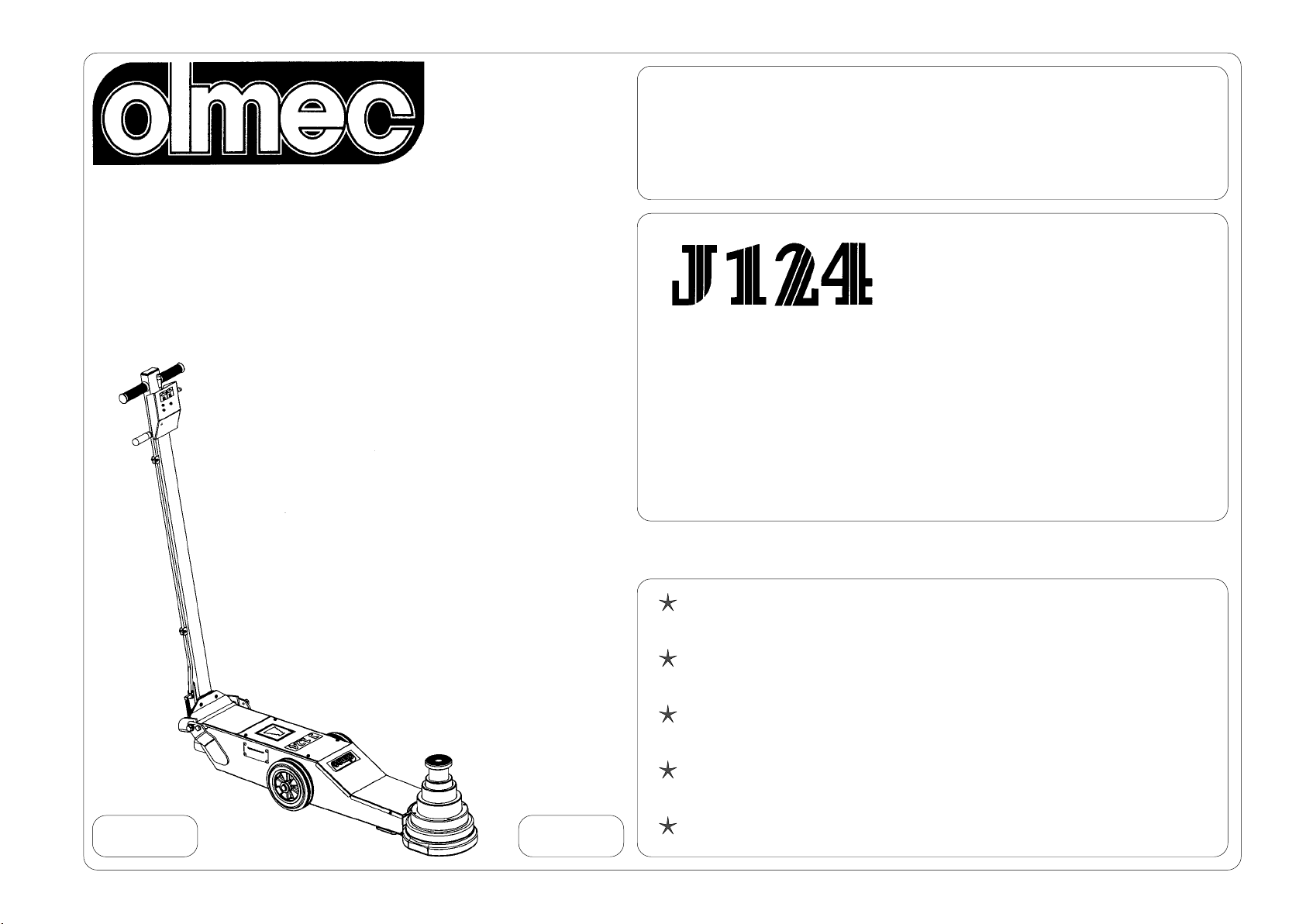
Cod. 7.020.0151 - Rev. 01/07
1 PRESENTATION 1 VORBEMERKUNG 1 PRESENTACION
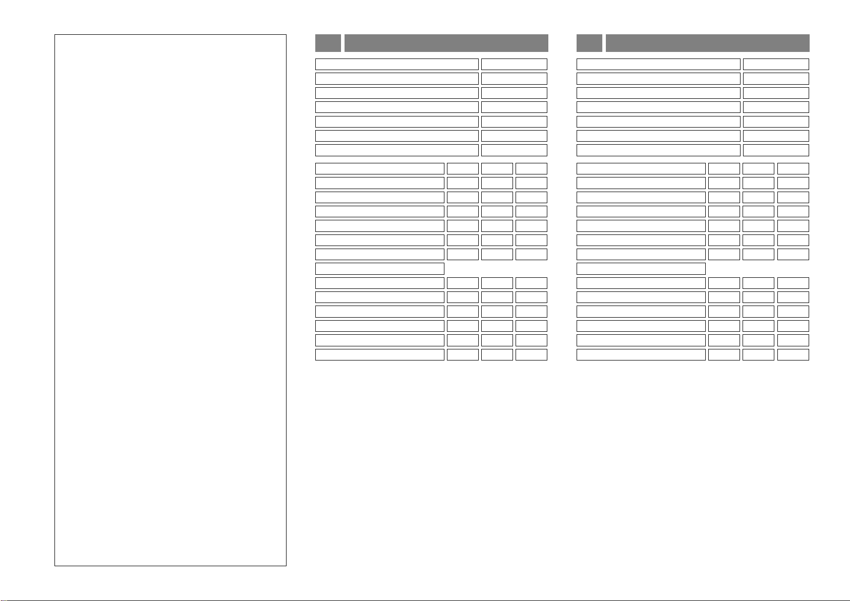
2 PLAQUE SIGNALETIQUE 2 DATEN DES TYPENSCHILDS 2 DATOS DE MATRICULA
3
CARACTERISTICAS TECNICAS
3 TECHNISCHE DATEN3
CARACTERISTIQUES TECHNIQUES
9
Cher Client,
le présent manuel d’instructions fait partie intégrante et
essentielle du produit et a pour but de faire connaître à
l’opérateurles normes fondamentaleset les critéres àsuivre
pour l’utilisation et l’entretien du cric.
Lescricshidropneumatiquesontétéconçuscommemoyen
de levage partiel dans le seul but de la dépose/repose de
la roue du véhicule.
Toute autre utilisation est considérée impropre et par
conséquent non autorisée.
Avant de commencer tout type d’opération il est
INDISPENSABLEdelireetdecomprendrece quiestindiqué
dans cette notice.
Le Constructeur ne sera pas responsable des dégâts
causés par une utilisation impropre de ses équipements.
CONSERVER SOIGNEUSEMENT CE MANUEL POUR
TOUTECONSULTATION ULTERIEURE.
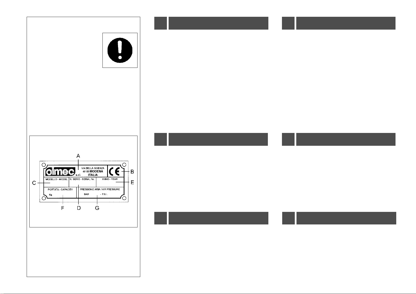
Sur le côté droit du cric se trouve une plaquette (fig.2/1)
d’identification de l’appareil reportant:
A- Données du constructeur
B- Marque CE (attestant la conformité à la Directive
98/37/CE du 22.06.1998 et ses modifications succ.)
C- Modèle du cric
D- Numéro de série
E- Année de construction
F- Charge maximale d’utilisation
G- Pression de l’air en BAR et P.S.I.
Dans la conception de l’élévateur, pour ce qui concerne la
vérification de durée à fatigue (résistance mécanique
structurelle), on a calculé une vie à fatigue égale à 200.000
(deuxcentmille)cyclesdelevage ;enconsidérantunedurée
de vie de 10 (dix) ans, cela correspond à un maximum de
50 ÷ 100 (cinquante ÷ cent) cycles de levage par jour.
Sehr geehrter Kunde,
das vorliegende Handbuch ist ein wesentlicher Bestandteil
des Produkts und dient dazu, dem Anwender die
grundlegenden Normen und Kriterien für Gebrauch und
Wartung des Wagenhebers zu vermitteln.
Die ölpneumatischen Wagenheber sind für das Anheben
vonFahrzeugen an einer SeitezumausschließlichenZweck
der Demontage bzw. Montage von Rädern ausgelegt.
Jede andere Verwendung ist als nicht vom Hersteller
vorgesehen zu betrachten und daher verboten. Bevor man
irgendeine Arbeit mit der Maschine beginnt, ist es
UNBEDINGTerforderlich, dieseAnleitungdurchzulesenund
ihren Inhalt zu verstehen. Der Hersteller haftet nicht für
Schäden,die durchdienicht vorgeseheneundunvernünftige
Benutzung ihrer Geräte entstehen.
DIESES HANDBUCH SORGFÄLTIG AUFBEWAHREN,
UM BEI BEDARF STETS DARIN NACHSCHLAGEN ZU
KÖNNEN.
Auf der rechten Seite des Wagenhebers befindet sich das
Kennschild (abb.2/1) mit folgenden Daten:
A- Herstellerdaten
B- CE Prüfzeichen (Konformität der Maschine 98/37/CE
vom22.06.1998 und ihren nachfolgenden Änderungen)
C- Maschinenmodell
D- Seriennummer der Maschine
E- Baujahr
F- Maximal zulässigeArbeitslast
G- Betriebsdruck in BAR und P.S.I.
Bei der Projektierung des Wagenhebers wurde bezüglich
der Zeit der Beständigkeit bis zur Ermüdung (mechanisch-
strukturelle Ermüdung) eine Betriebslebensdauer von 10
(zehn) Jahren mit ca. 200.000 (zweihunderttausend)
Hubzyklen veranschlagt; dies entspricht maximal 50 ÷ 100
(fünfzig ÷ hundert) Hubzyklen pro Tag.
Estimado Cliente,
este manual de instrucciones forma parte integrante y
esencial del producto y tiene por objeto poner en
conocimientodel operador las normas fundamentalesy los
criterios a adoptar durante el uso y el mantenimiento del
elevador.
Los elevadores oleoneumáticos han sido fabricados como
medios de elevación parcial, cuyo único fin es desmontar/
reinstalar una rueda del vehículo.
Cualquier otro uso es impropio y por tanto irracional y no
permitido. Antes de comenzar cualquier tipo de operación
es INDISPENSABLE leer y comprender cuanto muestra
estasinstrucciones.El fabricante nopuedeserconsiderado
responsable de daños causados por el uso impropio e
irracional de sus equipos.
CONSERVAR CON CUIDADO ESTE MANUAL PARA
CUALQUIER CONSULTAULTERIOR.
Enelcostadoderechodelelevadorha sido fijada una placa
(fig.2/1)deidentificacióndelamáquina,enlacualseindican:
A- Datos del fabricante
B- Marca CE (certifica la conformidad con la Directiva
98/37/CE du 22.06.1998 y sus sucesivas modific.)
C- Modelo de la máquina
D-Número de matrícula de la máquina
E- Año de fabricación
F-Carga máxima de uso
G- Presión aire de uso en BARES y P.S.I.
Por lo que se refiere a la verificación de resistencia a la
fatiga(resistencia mecánicaestructural),el proyecto delgato
contemplauna vida equivalente a 200.000(doscientos mil)
ciclos de elevación. Considerando una duración o vida útil
de 10 (diez) años, lo anterior corresponde a un máximo de
50 ÷ 100 (cincuenta ÷ cien) ciclos de elevación diarios.