SnapCab Focus User manual
Call 888-766-7834
Press 0 and ask for Pod
installation assistance
1199 Pod Installation Instructions 1 of 10 10/16/2020
Pod Installation Instructions
• All Necessary Safety Items/PPE
• Utility Knife
• Two (2) Cordless Drills/Drivers
• (1) 4-6 ft. Ladder
• 4”+ Long Magnetic Bit Holder
Meet 4 - 53” x 77” x 91”
Focus - 43.5” x 46” x 91” Meet 6 - 77” x 77” x 91”
Installation - Tools Needed
Notes before starting:
Evaluate existing room to ensure there are no obstructions that will interfere with placement of Pod.
Ensure building outlet is near final placement of Pod.
Determine whether or not your Pod can be transported preassembled to its final location.
Keep all material for one Pod together as parts are specific for each Pod.
• 4’ Level
• 1/2” Wrench
• Dead Blow Hammer/Mallet
• Panel Cart(s)
• (2) Vacuum Suction Cups with load
capacity of 100 lbs. per cup

Call 888-766-7834
Press 0 and ask for Pod
installation assistance
1199 Pod Installation Instructions 2 of 10 10/16/2020
SNAPCAB POD: MODELS FOCUS, MEET 4, MEET 6
IMPORTANT SAFETY INSTRUCTIONS
READ ALL INSTRUCTIONS PRIOR TO INSTALLING OR USING THE POD.
BASIC PRECAUTIONS SHOULD ALWAYS BE TAKEN WHEN USING AN ELECTRICAL FURNISHING.
POD IS FOR INDOOR USE ONLY
DANGER: TO REDUCE THE RISK OF ELECTRICAL SHOCK:
• DO NOT SPRAY CLEANERS OR OTHER LIQUIDS DIRECTLY ONTO OUTLETS, LIGHTS, AND OTHER ELECTRI-
CAL COMPONENTS.
• DO NOT ATTEMPT TO STICK ANYTHING OTHER THAN AN APPROVED PLUG INTO THE OUTLET SOCKETS
OF THE POD.
WARNING: TO REDUCE THE RISK OF BURNS, FIRE, ELECTRICAL SHOCK, OR INJURY TO PERSONS:
• MAKE SURE POD IS UNPLUGGED BEFORE ASSEMBLY OR DISASSEMBLY OF THE POD OR ANY PARTS OF
THE POD.
• ONLY CONNECT THE ELECTRICAL SYSTEMS IN THE POD AS DIRECTED BY THE MANUFACTURER. DO NOT
ATTEMPT TO ALTER OR MODIFY THE ELECTRICAL SYSTEM IN THE POD – DOING SO MAY RESULT IN PROP-
ERTY DAMAGE AND/OR PERSONAL INJURY.
• NEVER OPERATE THE POD IF IT HAS A DAMAGED POWER CORD OR PLUG. OR IF IT IS NOT WORKING
PROPERLY. CONTACT THE MANUFACTURER FOR REPAIR.
• KEEP THE CORD AWAY FROM HEATED SURFACES
• NEVER OPERATE THE POD WITH THE AIR OPENINGS BLOCKED.
• DO NOT OPERATE WHERE AEROSOL (SPRAY) PRODUCTS ARE BEING USED, OR IN LOCATIONS WHERE OX-
YGEN IS BEING ADMINISTERED
• DO NOT SIT OR STAND ON TABLE (WEIGHT RATING MAX LOAD FOCUS: 120LBS. MEET 4 AND MEET 6:
200LBS.)
WARNING: RISK OF ELECTRIC SHOCK – CONNECT THIS FURNISHING TO A PROPERLY GROUNDED OUTLET ONLY. SEE
GROUNDING INSTRUCTIONS.
GROUNDING INSTRUCTIONS
THIS PRODUCT IS DESIGNED FOR USE ON A NOMINAL 120-VOLT AC CIRCUIT AND HAS A GROUNDING PLUG. MAKE
SURE THE POD IS CONNECTED TO AN OUTLET HAVING THE SAME CONFIGURATION AS THE PLUG AND HAS BEEN
VERFIED THAT THE GOUND IS PROPERLY CONNECTED. DO NOT CONNECT THIS PRODUCT TO AN OUTLET USING AN
ADAPTER OF ANY KIND.
Call 888-766-7834
Press 0 and ask for Pod
installation assistance
1199 Pod Installation Instructions 3 of 10 10/16/2020
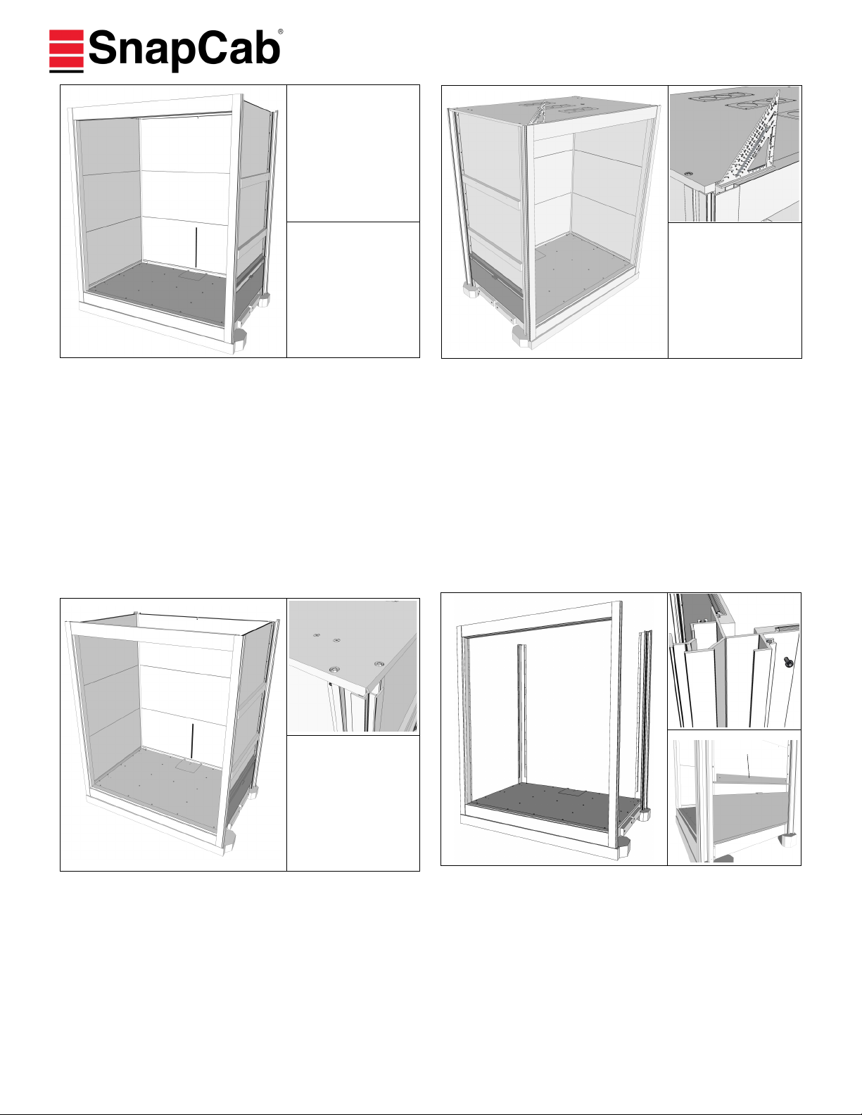
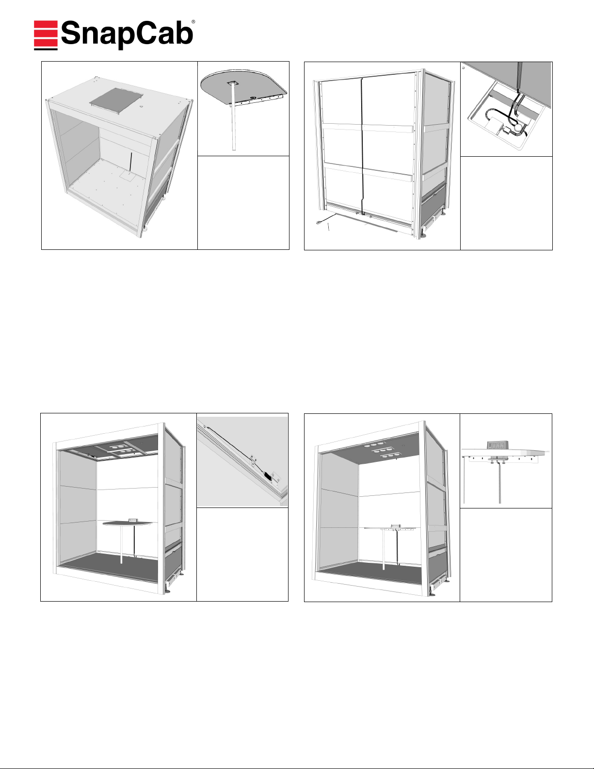
3. Remove Ceiling Canopy:
At each corner of Canopy Ceiling Sub-Assembly, remove six
(6) total 1/4”-20 x 1 1/2” Flange head bolts securing Cano-
py to Corner Extrusions. In a Focus or Meet 4, the Ceiling
Canopy is one piece. If a Meet 6 (two piece Ceiling Cano-
py), remove bolts along front and corners. Remove the bis-
cuits aligning the two Ceiling Canopy sections. Set aside
hardware for reassembly.
2. Determine which step to proceed with:
If preassembled Pod can be transported to its final destina-
tion, remove shipping corner blocks from under Pod using
provided 7/16” nut driver (requires Johnson bar or forklift).
Ensure outside edges of top and bottom horizontal pieces of
Front Frame Assembly are flush with ends of vertical extru-
sions of Front Frame Assembly. See Step 9. If not flush,
loosen nut, adjust, and tighten. Then proceed with Step 13.
If preassembled Pod cannot be transported to its final desti-
nation, proceed with Step 3 to disassemble. Keep all hard-
ware during disassembly as this hardware is required
to reassemble Pod. Do not remove any material pro-
tection at this time.
1. Unpack Pod:
Unpack Pod in convenient location.
Remove/dispose plastic Pod wrapping and cardboard pro-
tective corners. Open installation kit to access provided bit
(Red Bag).
Unstrap and place aside all material inside Pod. Remove
four (4) D-Rings screwed inside Pod on Floor Base and Ceil-
ing Canopy.
4. Remove Baffles, Interior Panels, Toe Kick Binder:
Remove baffles on lower row of panels first. Have one in-
staller inside Pod to support wall panels while the other
removes screws from outside Pod. Use provided bit to re-
move eight (8) #10 x 3/4” Round head square drive screws
holding each Panel to the Corner Extrusions. Start with Top
Panels and work your way down, setting Panels and hard-
ware aside for reassembly. When removing Side Wall Pan-
els, lift up and angle Panel away from Rear Corner Extru-
sion first, then remove from Front Corner Extrusion.
Remove Toe Kick Binder from inside of Pod
Baes
Call 888-766-7834
Press 0 and ask for Pod
installation assistance
1199 Pod Installation Instructions 4 of 10 10/16/2020
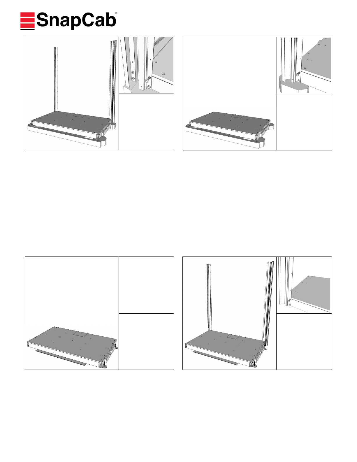
7. Position Floor Base:
Remove shipping corner blocks from under Pod using pro-
vided 7/16” nut driver. Position Floor Base on building floor
in area that provides access to assemble Pod. Keep in
mind, the Pod has casters and final positioning of Pod will
occur after assembly.
If seismic feet are provided, but not attached, attach (4)
total by threading on in each corner.
8. Attach Rear Corner Extrusions to Floor Base:
Match colored labels on Floor Base with colored labels on
each Corner Extrusion. Note: colored labels (Red, Yellow,
Blue) represent color label of each wall. With notched side
up, attach each Rear Corner Extrusion to the Floor Base
using two (2) provided 3/8 x 1-3/4" serrated flange bolts.
To allow adjustment, only hand tighten bolts (snug). Fully
tighten after Step 12.
6. Remove Rear Corner Extrusions from Floor Base:
Remove two (2) 3/8 x 1-3/4" Serrated Flange Bolts per cor-
ner, holding each Corner Extrusion to Floor Base. Set aside
hardware for reassembly.
After Corner Extrusions are removed, all components are
ready to move to final location for assembly.
5. Remove Front Frame Assembly from Floor Base:
Use provided 9/16” wrench to remove four (4) 3/8 x 1-3/4"
Serrated Flange bolts holding Front Corner Extrusions to
Floor Base. Set aside hardware for reassembly. DO NOT
remove the top Header or Sill piece connecting Front Cor-
ner Extrusions, unless assembly will not fit through door/
hallway. If disassembly is required, use 1/2” wrench to re-
move two (2) lock nuts in each corner. Set aside hardware
for reassembly.
Call 888-766-7834
Press 0 and ask for Pod
installation assistance
1199 Pod Installation Instructions 5 of 10 10/16/2020
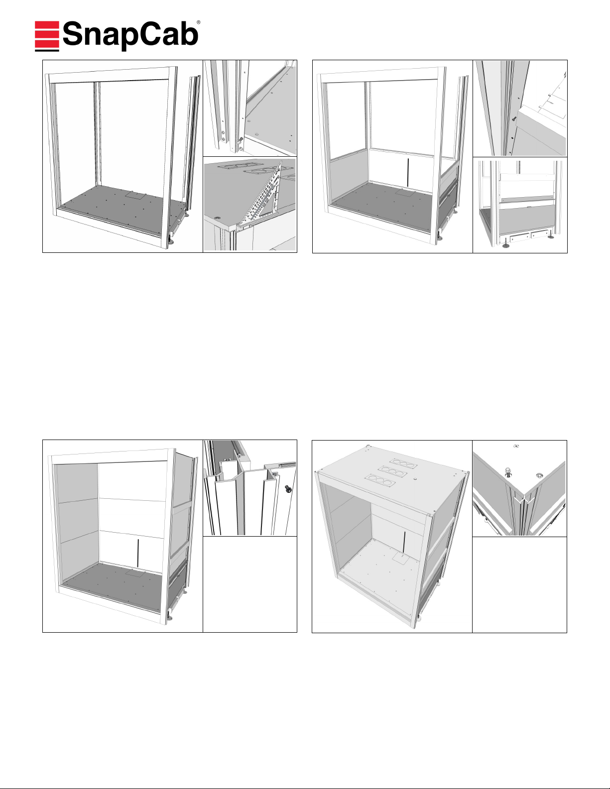
9. Attach Front Frame Assembly to Floor Base:
If Front Frame Assembly was disassembled, attach vertical
pieces to horizontal pieces by reinserting two (2) lock nuts
per corner. Ensure outside edges of top and bottom hori-
zontal pieces of Front Frame Assembly are flush with ends
of vertical extrusions of Front Frame Assembly. If not flush,
loosen nut, adjust, and tighten. Match colored labels for
placement and attach each front corner of Front Frame
Assembly to Floor Base by inserting four (4) provided 3/8 x
1-3/4" serrated flange bolts. To allow adjustment, only
hand tighten bolts at this time. Fully tighten bolts after Step
12.
10. Attach bottom row of Toe Kick Binders, Interior
Panels & Baffles:
Match colored labels on Floor Base with colored panel label
for placement. Reinstall Toe Kick Binder with #8-32 x 3/8”
machine screw, then install Red (side) panel, position so
blacked out tongue is inserted into Toe Kick Binder. Angle
Panel into Front Frame Assembly. Ensure opposite end of
panel notch sits into flange of Rear Corner Extrusion. Posi-
tion panels so existing holes line-up. Adjust Rear Corner Ex-
trusion as needed. From outside of Pod, attach by installing
eight (8) provided #10 x 3/4” silver round head square drive
screws per panel, through holes in Corner Extrusions and
tighten. Repeat for bottom Blue (side) and bottom Yellow
(rear) labeled panels.
11. Attach middle and top rows of Interior Panels:
Starting with Red (side) labeled panel, insert bottom
tongue of middle interior panel in previously installed interi-
or bottom panel. Ensure panel edges are flush. Repeat at-
tachment method of interior bottom panels. Note there will
be a decorative 1/8" black shadow line (gap) between in-
side face of all panels. Repeat for middle Blue (side) and
middle Yellow (rear) labeled panels. Repeat to attach top
row of interior panels.
12. Place Ceiling Canopy Note a Focus and Meet 4 will
have a one piece canopy. A Meet 6 will have a two (2) piece
canopy. Place Ceiling Canopy on top of Corner Extrusions
and Front Frame Extrusions. If a Meet 6, place second half
of Canopy Ceiling Sub-Assembly on top of Corner Extrusions
and Front Frame Extrusions, align biscuits, and push sections
tight together to interlock (no gap). Fasten the Canopy to
each of the Corner Extrusions using six (6) provided 1/4"-20
x 1-1/2" Flange head bolts and tighten. Tighten all bolts pre-
viously installed in Steps 8 and 9.
Call 888-766-7834
Press 0 and ask for Pod
installation assistance
1199 Pod Installation Instructions 6 of 10 10/16/2020
14. Install Electric:
Open floor hatch to access factory installed electrical system.
Uncoil main power cord and route it through notch in hatch
divider, across skid plate, and out under rear of Pod. Do not
remove preinstalled strain relief. Do not plug in now. Plug
Low Voltage power supply (found in Installation Kit) into
outlet on short leg of Power Distribution Unit. Run Low Volt-
age conduit up outside Rear Wall interior panels and through
hole on Top Panel. Connect Low Voltage Wire inside to Low
Voltage Power Supply in Pod Base. If no table, mount elec-
tric unit to notch hatch in floor hatch, then skip to Step 16.
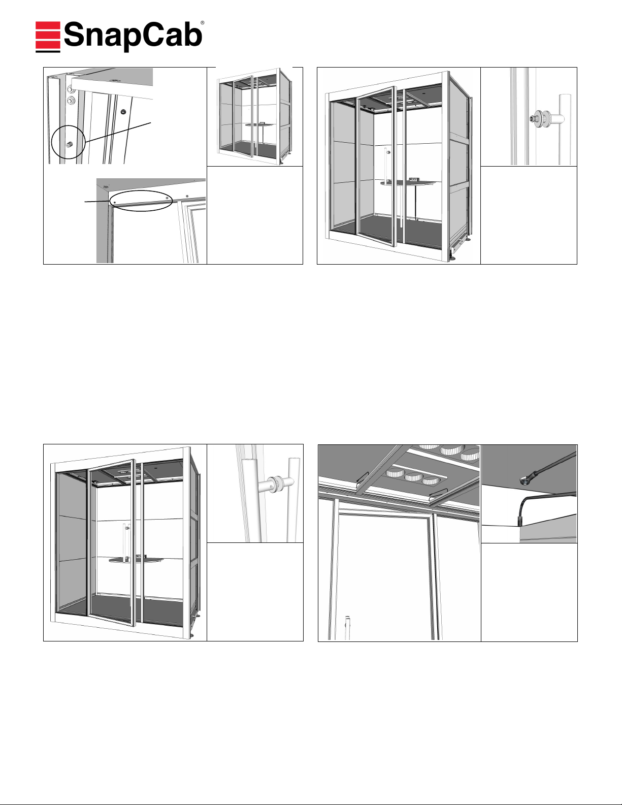
15. Install Drop Ceiling to Canopy:
Remove and set aside ceiling tiles. Partially thread in rear
1/4"-20 x 1" bolts into T-Nuts from inside Canopy. Lift Ceil-
ing into place and slide Rear Ceiling Legs onto partially in-
stalled bolts. Push Front Ceiling Legs up to make contact
with magnets on Canopy. Install the other two 1/4"-20 x 1"
bolts. Center Ceiling left to right, and make sure gap at
Yellow (rear) wall is even and has equal side wall gaps.
Tighten bolts and place pulley cable over pulley if provided.
13. Install floor mat & table leg:
Position mat in Pod with flap at rear of Pod and place onto
base. Pull carpet up tight to aluminum frame.
Remove protective covering on all bottom row panels. If pro-
vided, prepare Table for attachment, otherwise skip to Step
14. For Meet 4 or Meet 6, attach Table Leg to bottom of Ta-
ble by installing four (4) provided 1/4"-20 x 1/2" Pan head
machine screws through existing holes in Table Leg plate and
tighten.
If Pod was able to be moved to the final location without dis-
assembly, and Seismic/leveling feet were not installed, install
them now, one (1) in each corner.
Main Power Cord
16. Attach table:
Secure table mounted electric unit to notch in table by
tightening clamps. If installing a Focus, install brackets on
rear and side wall into predrilled holes with #10 x 3/4” Pan-
head Robertson, place table on brackets, line up holes on
bottom of table and secure with 1/4”-20 x 1/2” Pan-head
Machine screws. Run cord in back corner of Pod and along
back to the hatch. If Meet 4 or Meet 6, attach bracket(s)
to table first then fasten table assembly to rear wall. Run
cord into cable management strip down to hatch along rear
wall.

Call 888-766-7834
Press 0 and ask for Pod
installation assistance
1199 Pod Installation Instructions 7 of 10 10/16/2020
17. Install Glass Side Lights:
Focus—Skip to Step 18 (No Sidelight included)
Vertical trim of Glass Sidelight should face toward vertical extrusion. Insert top (black trim) of Glass Sidelight into top
channel of Front Frame Assembly. Lower bottom (silver trim) of Glass Sidelight into bottom channel of Front Frame
Assembly. Lift and slide Glass Sidelight into vertical Corner Extrusion, repeat to install second Glass Sidelight.
Place top filler block in header and secure with set screws.
18. Focus—Install Glass Door
Using suction cups, lift and angle door so that the tab at
the bottom of the door hinge sits closest to the red side of
the front frame. Move top of door so that the tab at the top
of the door slides through channel in header and ends up
tight to red side of Front Frame. With one person holding
the door in place, insert three (3) 3/8 x 1-3/4” serrated
flange bolts into predrilled holes at outside of vertical extru-
sion. This will secure door right to Front Frame.
Place bottom filler block in sill. Take Strike Post and angle
diagonally inside Front Frame opening, careful not to
scratch the front frame. Then move top tab over so Strike
Post is tight to blue side of Front Frame. Fasten using same
method that was used to install the door. Place Top Filler
Block in header and secure using set screws.
19. Meet 4 and Meet 6—Install Glass Door
Have one installer push up strike side of top filler block tem-
porarily by loosening set screw holding it, tighten center set
screw to pin it in place temporarily. Take provided Strike
Post and angle diagonally inside Front Frame opening, care-
ful not to scratch Front Frame. Then move top tab over so
Strike Post captures sidelight.
Have one installer push up door side of the top filler block.
temporarily by loosening set screw holding it, tighten center
set screw to pin it in place temporarily. Using suction cups
lift and angle bottom of door to input tab at bottom of door
hinge between Bottom Filler Block and Left Sidelight. Move
top of door over to sidelight so door frame captures the
glass sidelight. With door in place, set Top Filler Block in
top channel. Place bottom filler block in sill.
Top Door Filler Block
Call 888-766-7834
Press 0 and ask for Pod
installation assistance
1199 Pod Installation Instructions 8 of 10 10/16/2020
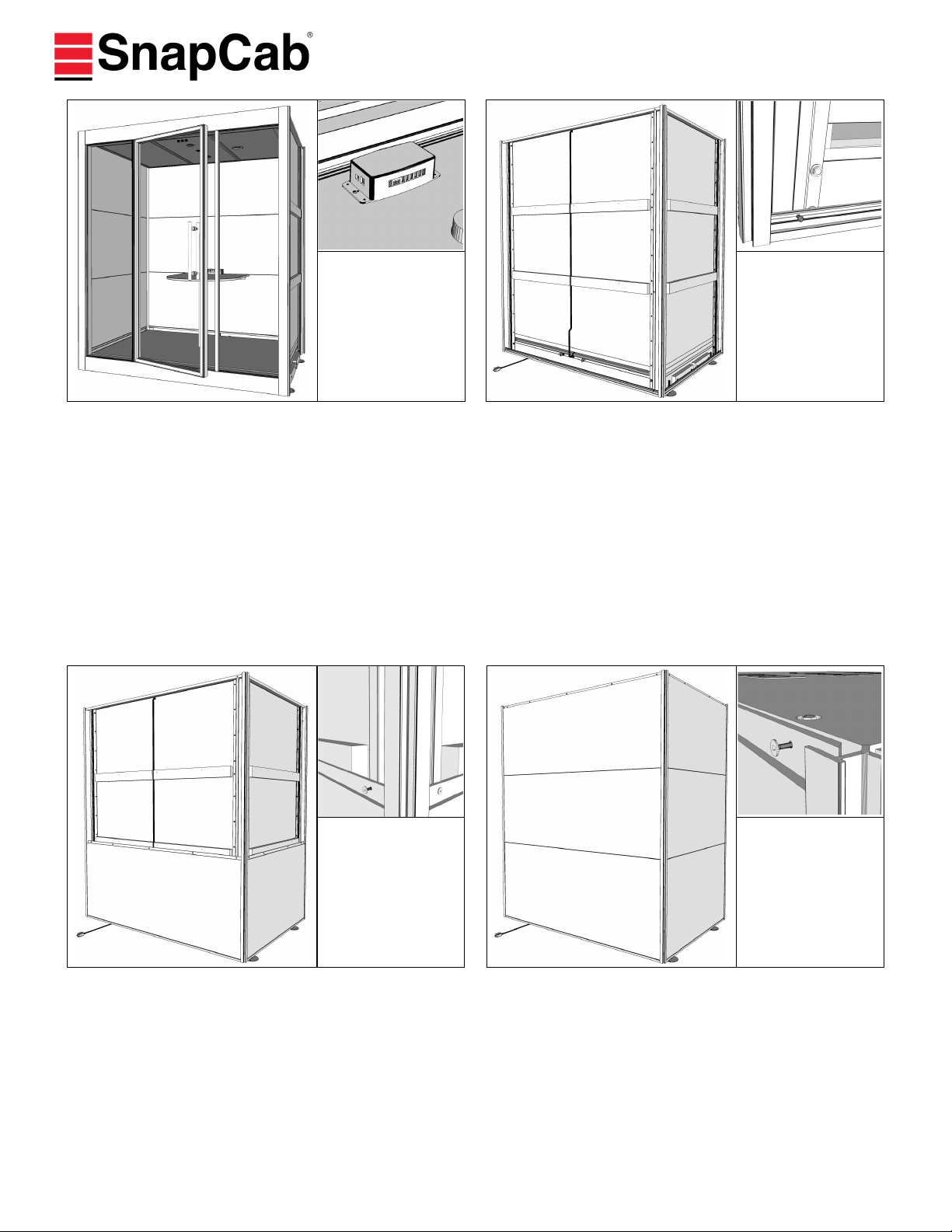
23. Secure Ceiling:
Fasten cable stop attached to front of Ceiling Frame to
Canopy using provided #10 x 3/4" round head square drive
screw. A pre-drilled pilot hole is in Canopy directly above
cable stop attachment point on Ceiling Frame. Meet 4 and
Meet 6 have two (2) cable stops, attach both. On Meet 4
and Meet 6, place cable attached between spring and ceil-
ing frame over the Pulley Wheel attached to Canopy.
21. Install Exterior Door Pull:
Loosen four set screws holding interior door pull. Remove
screw attached to exterior door pull. From inward side of
door, insert screw with attached stem through washer and
gasket into top Glass Door hole. Plastic portion of washer
should be against glass. From outward side of Glass Door
place washer over screw thread. Loosely attach Exterior
Door Pull (side without set screws) by hand threading
screw into Door Pull. Repeat for bottom attachment. Tight-
en both screws.
22. Install Interior Door Pull:
Slide Interior Door Pull over screws with attached stem.
Tighten set screws.
20. Adjust and Secure Glass Sidelight(s):
Focus—Skip to Step 21
Meet 4 and Meet 6—From outside Pod take provided
green tip set screws and insert into predrilled holes in
Front Frame Vertical Extrusions. Tighten so sidelights
push tight against Top and Bottom Filler Blocks. Do not
over tighten.
From inside Pod, lower front of drop ceiling and fully
tighten remaining set screws in Header to finish securing
Glass Sidelights.
Test door opening and closing, adjust glass sidelights as
needed with set screws.
Top Set
Screws
Side Set
Screws
A
B
C
Call 888-766-7834
Press 0 and ask for Pod
installation assistance
1199 Pod Installation Instructions 9 of 10 10/16/2020
25. Attach Toe Kick Binders to Corner Extrusions:
*If Focus should be fastened to floor, complete steps in
supplemental instructions "Pod Floor Fastening Instruc-
tions" before continuing. Match colored labels for place-
ment of Toe Kick Binders. Angle Toe Kick Binder into Cor-
ner Extrusion and slide into/behind opposing Corner Extru-
sion. Position so existing holes line-up. Fasten Toe Kick
Binders in place through predrilled holes using provided 8-
32 x 3/8” machine screws.
27. Attach middle and top row Exterior Panels:
Starting with Red (side) Panel, insert panel into Corner Ex-
trusion and lower bottom tongue into top tongue of lower
panel. Using 1 1/4" SnapCab panel screws, attach wall pan-
els. Note, there will be a decorative 1/8" black shadow line
(gap) between the face of the panels. Repeat for Blue
(side) and Yellow (rear) panels.
26. Attach bottom row of Exterior Panels:
Match colored labels on Floor Base with colored panel label
for placement. Start with Red (side) panel, insert front
edge of panel into Front Corner Extrusion and lower bot-
tom tongue of panel into previously installed Toe Kick Bind-
er. For ease of installation, insert beveled side of panels
first. Position panels so existing holes line-up. From outside
of Pod, attach panels using 1-1/4" SnapCab Panel screws.
Repeat for bottom Blue (side) and bottom Yellow (rear)
panels.
24. Connect Wires, Install Ceiling Tiles:
Install Ceiling Tile without any holes/lights on Red wall (left
side) of ceiling frame. Connect Low Voltage cable from Yel-
low (rear) wall to Low Voltage Control Unit on ceiling tile.
On Meet 4 and Meet 6, install right ceiling tile with knock-
out for fire suppression. Connect Ventilation Fans to labeled
USB Ports on Low Voltage Control Unit. Downlights and
motion sensor will be connected from the factory. If rear
perimeter light is provided, connect to designated location
on Low Voltage Control Unit.
Call 888-766-7834
Press 0 and ask for Pod
installation assistance
1199 Pod Installation Instructions 10 of 10 10/16/2020
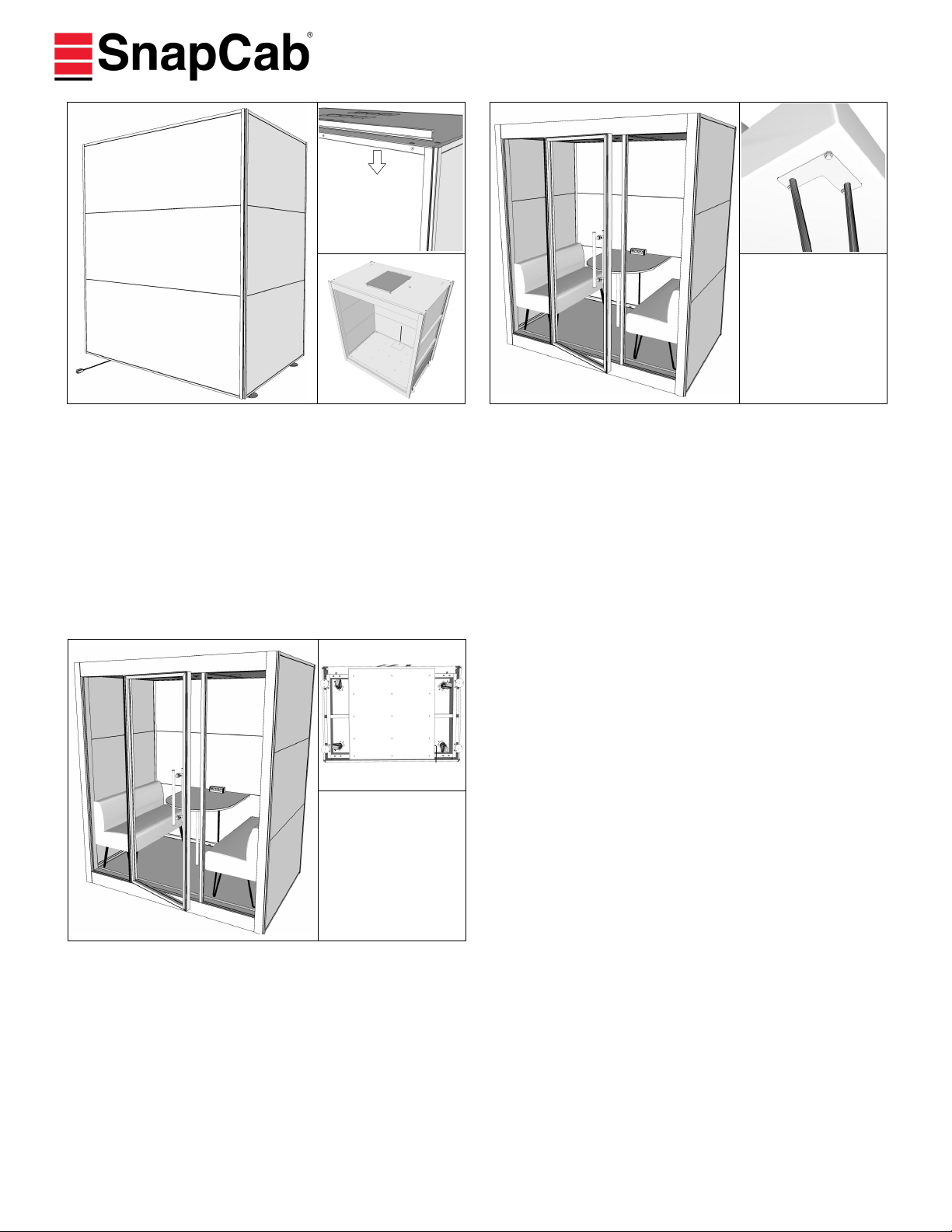
29. Install Benches, if Applicable:
Attach legs to base on bench(es) by inserting (3) provided
1/4—20 x 1” Serrated Flange Bolts per leg through existing
pre-drilled holes and tighten. Insert bench(es) into Pod.
28. Install External Top Caps and set Fan Cover:
Match colored labels for placement. Place tongue of Exteri-
or Top Cap in groove of Exterior Top panels. Press down
until Top Cap securely seats in groove of wall panel. If
needed, lightly tap in with rubber mallet. Top Cap should
be flush with top of Corner Extrusions.
Rest fan cover directly over fans.
30. Position Pod, Adjust, and Clean:
If Pod is not in final location, move it there now. Adjust
Leveling Feet to level Pod by turning them up or down.
This will also keep the Pod from moving when in use. Re-
move protective films, tapes, and any visible labels.
Plug Pod into outlet and adjust lights to desired brightness.
Clean Pod using provided glass cleaner and paper towels,
leave remaining cleaning supplies with end user. Put trash
in supplied trash bag and dispose. Take some great in-
stalled Pod pictures and email them to
This manual suits for next models
2


