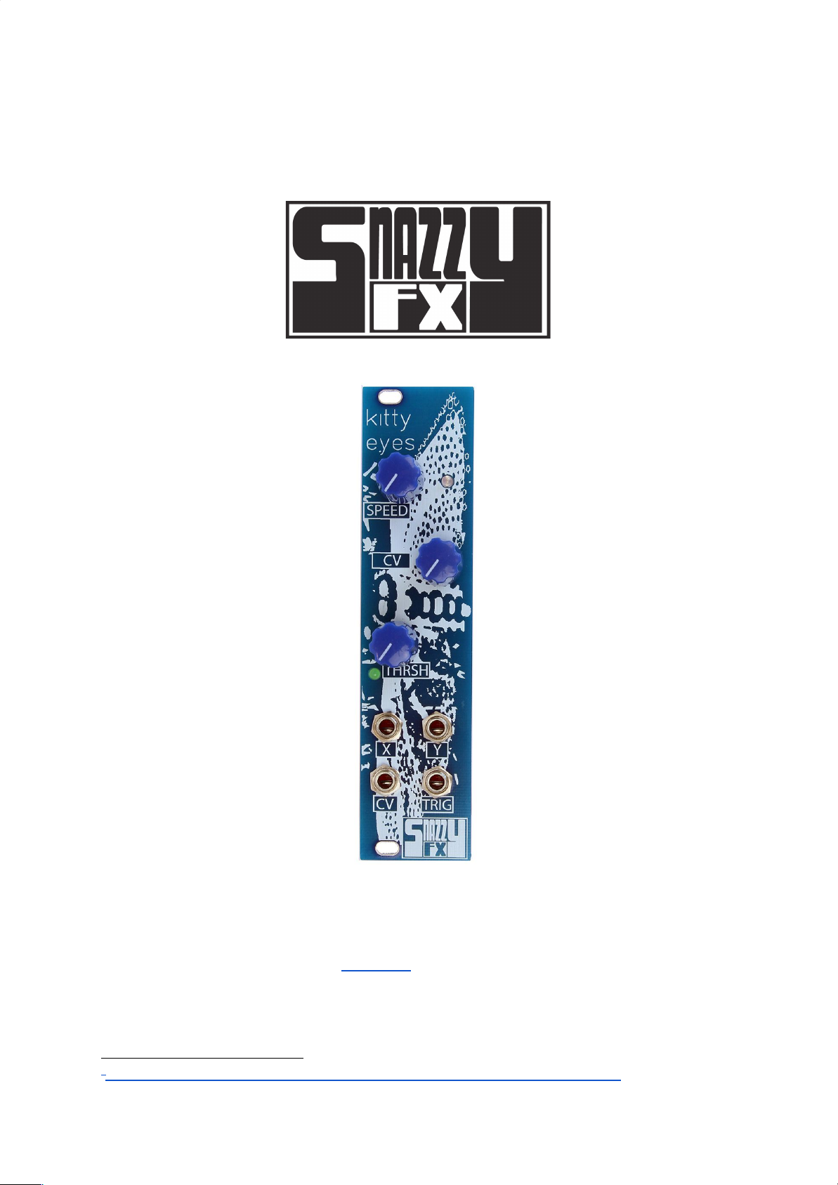
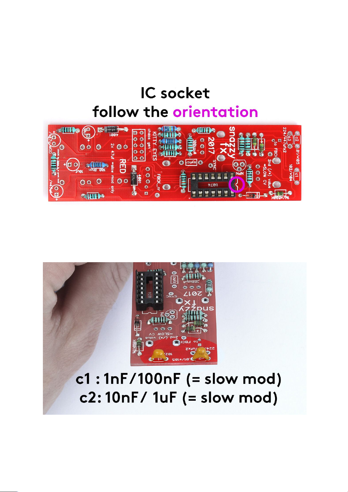
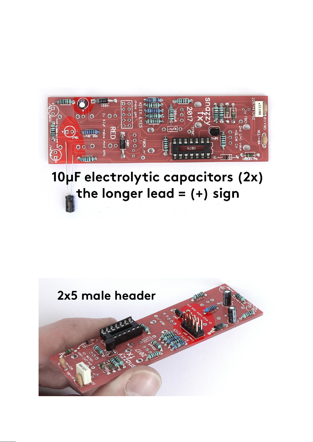
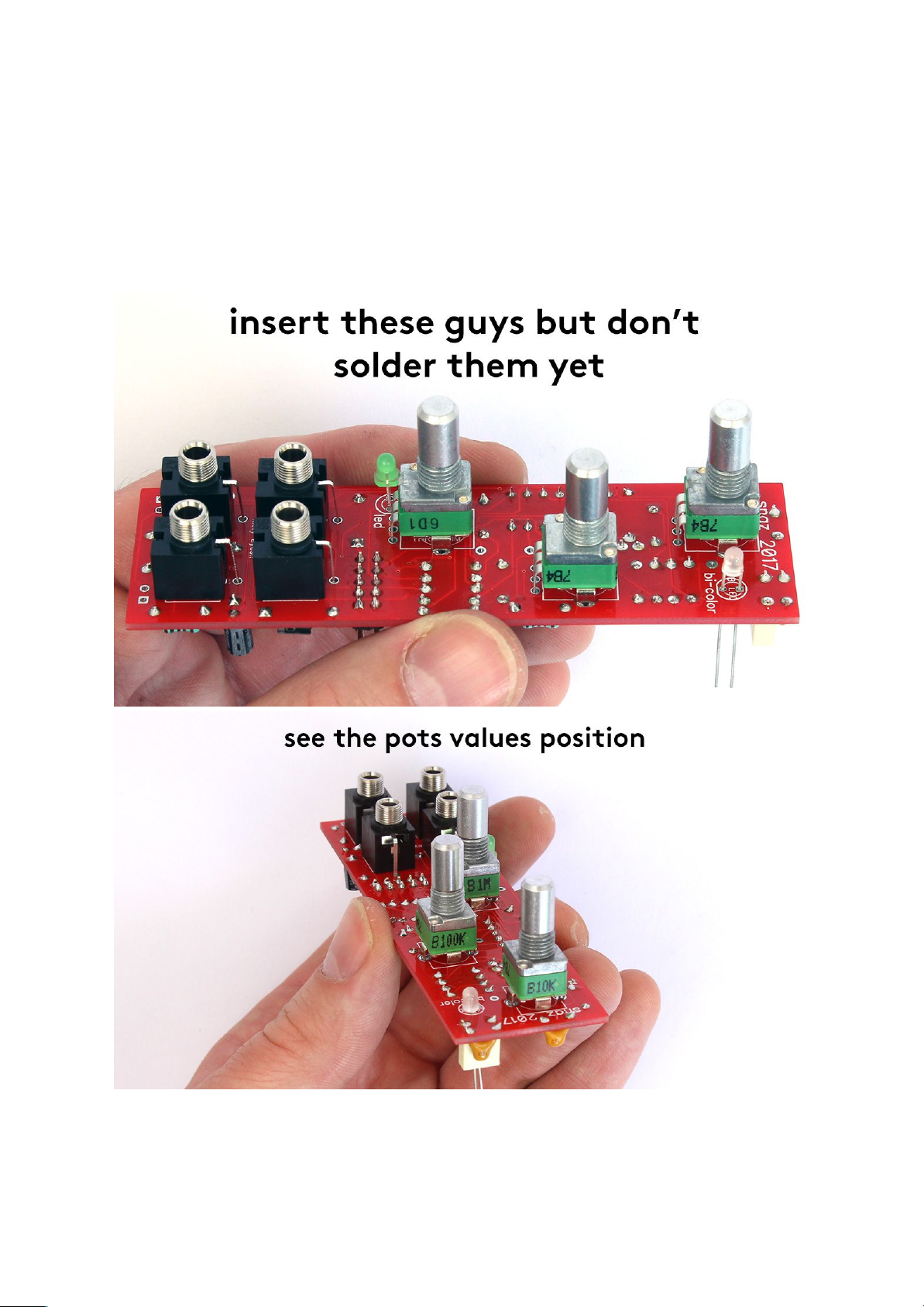
Snazzy FX Kitty Eyes User manual

last update: 27. 9. 2017
KITTY EYES - Assembly Guide
snazzyfx.com
INTRODUCTION
This guide is for building KITTY EYES module by SNAZZY FX. It is good to have basic soldering
skills and to be able to identify electronic components before starting this kit. However if you have
never soldered before, check out this tutorial first . We even included some of the best quality solder
1
to help you solder everything faster and better.
This kit consists of just one printed circuit board (PCB). See the Bill of Materials (BOM) for detailed list
of all components.
1 https://cdn-learn.adafruit.com/downloads/pdf/adafruit-guide-excellent-soldering.pdf
1

IMPORTANT NOTE: You can choose to build Kitty Eyes in the default or slow mod as you got
components for both of these. Keep an attention for the notes in the resistors and capacitors section.
KITTY EYES BOM
qty
value
part
RESISTORS
1
sync
unpopulated
2
100R
1/4W
1
220R
1/4W
5
1k
1/4W
2
2k2
1/4W
2
10k
1/4W
2
47k
1/4W
2
100k
1/4W
1
1M/ 820k
1/4W
1
2M2
1/4W
CAPACITORS
1
1nF
CER/FILM4
1
100nF
ceramic capacitor (slow mod)
1
220nF
CER/FILM4
1
10nf
CER/FILM4
1
1uF
ceramic capacitor (slow mod)
2
10uF
electrolytic capacitor
2
47uF
electrolytic capacitor (slow mod)
SEMICONDUCTORS
2
1N4007
diode
1
1N4148
diode
1
LED 3 mm G D
1
LED bicolor
1
2N3904T
transistor
1
TL074
TL074AN
POTS
1
POT LIN B 10K
linear potentiometer
1
POT LIN B 100K
linear potentiometer
1
POT LIN B 1M
linear potentiometer
HARDWARE
4
thonkiconn jack
1
2 x 5 pin
male pinheader
1
dip 14 socket
2

ASSEMBLY
3
knob
3
big nut pots
4
nut jack
1
front panel
1
power cable 10-16
2
panel screw
Before starting this kit, prepare the following tools:
● Soldering iron
● Multi-meter
● Flush cutters
● Phillips screwdriver
● Flat screwdriver
● Wrench No. 8
● Protective eyewear
We suggest that you work in a clean, well lit and ventilated environment to avoid accidents or losing
any of the small components.
Also briefly go through this guide and make sure that you understand all the steps.
3

SOLDERING
Before you start soldering, take your time and find all the resistors values using a multimeter (or you
2
can check the color codes if you are seasoned enough).
RESISTORS
There are eighteen resistors of different values: 2x 100R, 1x 220R, 5x 1k, 2x 2k2, 2x 10k, 2x 47k, 2x
100k, 1x 1M / 820k*, 1x 2M2). Be careful to insert these resistors on the right place (rectangular with
appropriate value) and solder them. Then snip the overhanging leads (be sure to make this step on all
remaining leads in the course of this guide).
*IMPORTANT NOTE: for slow mod solder the 820k resistor instead of 1M one. And to not let you get
confused: the "sync" rectangular remains unpopulated.
2 https://learn.sparkfun.com/tutorials/how-to-use-a-multimeter/measuring-resistance
4

5

6

DIODES
After that solder the diodes: 1x 1N4148, 2x 1N4007. Place the latter ones in "4001" rectangular. Be
careful, diodes are polarized! Make sure that the stripe on the diode body matches the stripe on the
PCB. Check the photo below.
7

IC SOCKET
Let's populate the PCB with the IC socket (14 pin). Make sure that the notch on the socket
matches the print on the board.
CERAMIC CAPACITORS
Now you can add the ceramic capacitors. There is one 1nF (marked "102" on itself) that goes to the
"c1" spot and one 10nF (marked "103" on itself) that goes to the "c2" spot. IMPORTANT NOTE: for
slow mod solder 100nF ("104") instead of 1nF and 1uF ("105") instead of 10nF.
8

TRANSISTOR
Solder also the 2N3904 transistor. The flat side has to match with the printing on the PCB.
FILM CAPACITOR
The next capacitor to solder is the film one (220nF) that goes on the "c3" spot. IMPORTANT NOTE:
for slow mod DO NOT solder this component, leave this spot unpopulated.
9

ELECTROLYTIC CAPACITOR
There are also two electrolytic capacitors (10μF)*.These ones are polarized! There is a plus (+)
sign on the PCB that should match the longer lead of the electrolytic capacitor (actually the minus (–)
side is also marked on the body of the capacitor with a white strip).
* IMPORTANT NOTE: for slow mod solder also the two 47μF caps.
POWER CONNECTOR
Solder the male pinheader now. Be careful to solder it straight. You may first solder just one of the
pin, take the board in your hand and re-heat that pin while pressing down on the header to align it (be
careful, you don’t want to touch the pin you are heating up). Wait for it to cool and solder the rest of
the pins.
10

POTS, JACKS AND LEDs WITH PANEL
You are almost done. Let's do the rest of the components. Turn the PCB around and insert jacks (4x)
and potentiometers (3x) of different values: B10k, B100k and B1M - be sure to insert them on the
right place. Insert also the LEDs: the green one goes to the bottom. Watch out for orientation! The
longer lead has to go into the square hole on PCB. Don't solder these guys yet!
11

Place the front panel on and mount the pots and jacks with nuts.
Check the position of all the parts if they are flat on the board, push the LEDs to the panel and do the
soldering.
12

IC
Don't forget to insert the IC into the socket. Installing the IC can be a little tricky. The IC leads are
flared out a bit wider than the socket will accept. Bend them in slightly with your fingers, and then try
to press all the leads into the sockets in one shot. IMPORTANT: the notch on ICs has to match
with the notch on the socket.
13

ASSEMBLY
Now just add the knobs and your KITTY EYES module is ready to go! Before you connect anything,
make sure that your system is disconnected from power. Also double check the polarity of the ribbon
cable, the red cable should match the -12V rail both on the module and on the bus board!
14
Other manuals for Kitty Eyes
1
Table of contents