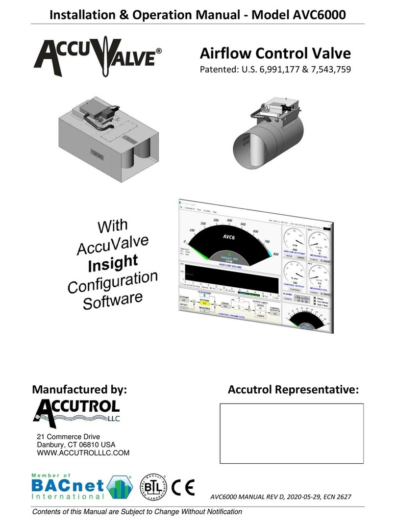
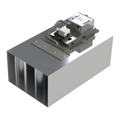
Accutrol AccuValve AVC4000 User manual

Installation & Operation Manual - Model AVC4000
Contents of this Manual are Subject to Change Without Notification
Manufactured by: Accutrol Representative:
AVC4000 MANUAL REV B, 2022-03-04, ECN 2772
21 Commerce Drive
Danbury, CT 06810 USA
WWW.ACCUTROLLLC.COM
Airflow Control Valve
Patented: U.S. 6,991,177 & 7,543,759

Installation & Operation Manual - Model AVC4000
Contents of this Manual are Subject to Change Without Notification Page ii
LIMITED WARRANTY
Accutrol LLC, having its principal place of business at 21 Commerce Drive, Danbury, CT USA
("Manufacturer") warrants its AccuValve®, Model AVC4000 product (the "Products") as follows:
1. Limited Warranty.
Manufacturer warrants that the Products sold hereunder will be free from defects in material
and workmanship for a period of sixty (60) months from the date of purchase. If the Products do
not conform to this Limited Warranty during the warranty period (as herein above specified),
Buyer shall notify Manufacturer in writing of the claimed defects and demonstrate to
Manufacturer’s satisfaction that said defects are covered by this Limited Warranty. If the defects
are properly reported to Manufacturer within the warranty period, and the defects are of such
type and nature as to be covered by this warranty, Manufacturer shall, at its own expense,
furnish, replacement Products or, at Manufacturer's option, replacement parts or services for
the defective Products. Shipping and installation of the replacement Products or replacement
parts shall be at Buyer's expense.
2. Other Limits.
THE FOREGOING IS IN LIEU OF ALL OTHER WARRANTIES, EXPRESS OR IMPLIED, INCLUDING BUT
NOT LIMITED TO THE IMPLIED WARRANTIES OF MERCHANTABILITY AND FITNESS FOR A
PARTICULAR PURPOSE. Manufacturer does not warrant against damages or defects arising out
of improper or abnormal use or handling of the Products; against defects or damages arising from
improper installation (where installation is by persons other than Manufacturer), against defects
in products or components not manufactured by Manufacturer, or against damages resulting
from such non-Manufacturer made products or components. Manufacturer passes on to Buyer
the warranty it received (if any) from the maker thereof of such non-Manufacturer made
products or components. This warranty also does not apply to Products upon which repairs have
been affected or attempted by persons other than Manufacturer or pursuant to written
authorization by Manufacturer. This warranty also does not apply to any product provided by
the Buyer and mounted by the Manufacturer to Products.
3. Exclusive Obligation.
THIS WARRANTY IS EXCLUSIVE. The sole and exclusive obligation of Manufacturer shall be to
repair or replace the defective Products in the manner and for the period provided above.
Manufacturer shall not have any other obligation with respect to the Products or any part
thereof, whether based on contract, tort, and strict liability or otherwise. Under no
circumstances, whether based on this Limited Warranty or otherwise, shall Manufacturer be
liable for incidental, special, or consequential damages.
4. Other Statements.
Manufacturer's employees or representatives' ORAL OR OTHER WRITTEN STATEMENTS DO NOT
CONSTITUTE WARRANTIES, shall not be relied upon by Buyer, and are not a part of the contract
for sale or this limited warranty.
5. Entire Obligation.
This Limited Warranty states the entire obligation of Manufacturer with respect to the Products.
If any part of this Limited Warranty is determined to be void or illegal, the remainder shall remain
in full force and effect.
Installation & Operation Manual - Model AVC4000
Contents of this Manual are Subject to Change Without Notification Page iii
TABLE OF CONTENTS
LIMITED WARRANTY................................................................................................................ii
TABLE OF CONTENTS...............................................................................................................iii
SECTION 1 - INTRODUCTION................................................................................................... 4
SECTION 2 –SPECIFICATIONS................................................................................................. 5
SECTION 3 –PHYSICAL DIMENSIONS & WEIGHTS .......................................................... 11
SECTION 4 - INSTALLATION .................................................................................................. 12
SECTION 5 –WIRING................................................................................................................ 15
SECTION 6 –ACCUVALVE INSIGHT CONFIGURATION SOFTWARE ............................ 16
SECTION 7 –BACnet.................................................................................................................. 31
SECTION 8 –MAINTENANCE ................................................................................................. 37
APPENDIX A: BLUETOOTH...................................................................................................... A

Installation & Operation Manual - Model AVC4000
Contents of this Manual are Subject to Change Without Notification Page 4
SECTION 1 - INTRODUCTION
The AVC product family integrates a high-performance controller with the revolutionary award
winning AccuValve®product. The Engineers at Accutrol have used technology and innovation
to make the AVC AccuValve®not only the most advanced airflow control valve in the industry,
but also the most reliable and intuitive airflow control valve available.
1.1 Theory of Operation (Reference the Diagram Below)
The AccuValve®divides the airflow into two equal chambers using an airfoil shaped
compression section. Each chamber is comprised of a vortex shedding airflow sensor, a
modulating control blade and a static regain section. As air enters the chambers it accelerates
and compresses, creating an ideal zone for measuring airflow velocity. The vortex shedding
airflow sensors provide a highly repeatable digital pulse-train with a frequency that is directly
proportional to the air flow velocity in each chamber of the AccuValve®.
The digital signal generated by each vortex shedding sensor provides a direct measurement of
the volumetric flow rate in each chamber of the AccuValve®. The airflow measurement
provides closed-loop feedback to the ePI®controller which modulates the valve actuator to
maintain the desired airflow set point. The airflow set point can be provided from either,
analog input, digital input, communications over BACnet MS/TP or AVC internal program
memory. The AVC also provides analog output signals.
For network communications, the AVC provides an EIA-485 port supporting BACnet MS/TP as a
Full Master Node state machine. Field programming is accomplished through AccuValve
Insight, which is an intuitive user-interface software. Connection between the AVC and
computer is provided through a USB port located on the AVC control module or through an
optional wireless Bluetooth connection.

Installation & Operation Manual - Model AVC4000
Contents of this Manual are Subject to Change Without Notification Page 5
1.2 Model Code
A V C 4
-
-
VALVE MATERIAL
2 = 304ss, 20 Ga.
3 = 316ss, 20 Ga.
4 = Aluminum, 16 Ga.
VALVE SIZE
06 = 6" Diameter
08 = 8" Diameter
10 = 10" Diameter
12 = 12" Diameter
14 = 14" Diameter
18 = 12" h x 18" w
24 = 12" h x 24" w
ACTUATOR
17 = Fail Last Position (FLP) 10-sec full cycle
OPTIONS
F = Flanges, Van Stone
I = Insulation
S = Tight Shut-off
W = Wireless Bluetooth
1.3 Valve Types
Round AccuValve
Sizes 06, 08, 10, 12 and 14
Rectangular AccuValve
Sizes 18 and 24

Installation & Operation Manual - Model AVC4000
Contents of this Manual are Subject to Change Without Notification Page 6
SECTION 2 –SPECIFICATIONS
PERFORMANCE
Accuracy
+/- 5% of reading or 5 CFM, whichever is greater
Speed of Response
< 1 second control signal response (full stroke cycle time is 10 seconds)
Shut-off Leakage Rate
Standard: < 1.5% FS at max operating pressure
"S" Option: < 0.5% FS round valves, < 1% FS rectangular valves @ max operating pressure
Max Operating Pressure
3”wc Differential Pressure Across Valve
Min Operating Pressure
Reference Section 2.1
Airflow Range
Reference Section 2.1
Failure Mode
Last Position
ENVIRONMENTAL
Temperature
Airstream: -20 to 165 deg. F for all Standard Valve Models
Ambient: -20 to 125 deg. F Storage: -40 to 165 deg. F
Humidity
0 to 90% non-condensing
ELECTRICAL
Power:
24VAC +/- 20% 50/60Hz. (Class 2 Power Source) 17VA
24VDC +/- 10%, 9W
Analog Input:
Software Selectable: Voltage, Current or Resistance
Voltage: 0-10v Range, Input Impedance = 100K ohms
Current: 0-20mA Range, Input Impedance = 500 ohms
Resistance: 0-20K Range, 500uA Internal Current Source
Digital Inputs:
2 dry-contact inputs
Analog Output:
Software Selectable: 0-20mA, 4-20mA, 0-10V, 2-10V, 0-5V or 1-5V
V-out capable of driving 1 K-ohm load @ 10V, I-out capable of driving 1K-ohm load
RS-485:
EIA 485 BACnet MS/TP 2-wire, Receiver Impedance: ¼ unit load
Note: Network bias and field termination are NOT provided by the AVC Control Module
Configuration Port:
USB Type C, Wireless Bluetooth (Optional)
Power: 2-Position, vertical pluggable, Wire Size range - 18-30 AWG
IO: 7-Position terminal block, Wire size range - 16-30 AWG
BACnet: 2-Position terminal block, Wire size range - 16-30 AWG
Compliance
, RoHS, BTL Listed
Electromagnetic
Compatibility
2014/30/EU, EMC Directive
EN61236-1:2013
2014/53/EU, Radio Equipment Directive
EN301489-1, V1.9.2:2011
ETSI EN301489-1, V2.2.0:2017
ETSI EN301489-3, V1.6.1:2013/V2.1.1:2017
ETSI EN301489-17, V2.2.1:2012/V3.2.0:2017
Product Safety
2014/35/EU, Low Voltage Directive
EN61010-1:2010/A1:2019/AC:2019

Installation & Operation Manual - Model AVC4000
Contents of this Manual are Subject to Change Without Notification Page 7
SPECIFICATIONS CONTINUED
FCC Part 15
This equipment has been tested and found to comply with the limits for a Class A digital
device, pursuant to Part 15 of the FCC Rules. These limits are designed to provide reasonable
protection against harmful interference when the equipment is operated in a commercial
environment. This equipment generates, uses, and can radiate radio frequency energy and, if
not installed and used in accordance with the instruction manual, may cause harmful
interference to radio communications. Operation of this equipment in a residential area is
likely to cause harmful interference in which case the user will be required to correct the
interference at the user’s own expense. This Class A digital apparatus meets all requirements
of the Canadian Interference-Causing Equipment Regulations.
Units provided with the optional Bluetooth low energy module contain
FCC ID: XPYNINAB1
IC: 8595A-NINAB1
This device complies with Part 15 of the FCC Rules. Operation is subject to the following
two conditions;
(1) This device may not cause harmful interference, and
(2) This device must accept any interference received, including interference that
may cause undesired operation.
KCC South Korea compliance certification number MSIP-CRM-ULX-NINA-B111
Australia and New Zealand regulatory compliance. The NINA-B1 modules are compliant
with AS/NZS 4268:2012?AMDT 1:2013 standard –Radio equipment and systems –Short
range devices –Limits and methods of standard measurement made by the Australian
Communications and Media Authority (ACMA)
MATERIALS OF CONSTRUCTION
Model Code Material Designator
(2) 304SS
(3) 316SS
(4) Aluminum
Housing
304L SS
316L SS
Alum.5052-H32
Compression Section
304L SS
316L SS
Alum.5052-H32
Static Regain Section
304L SS
316L SS
Alum.5052-H32
End Plate
304L SS
316L SS
Glv. Steel
Blades
304L SS
316L SS
Glv. Steel
Shafts
316L SS
316L SS
316L SS
Shaft Bearings
Teflon
Teflon
Teflon
Vortex Sensors
Polycarbonate UL94-VO
Sensor Tubing
Polyurethane, Ether-based
Compression Seals
Viton Rubber
Viton Rubber
EPDM Rubber
Machine Screws
304SS
316SS
304SS
Rivets
304SS
316SS
304SS
Blade Seals (optional)
Viton Rubber
Viton Rubber
EPDM Rubber

Installation & Operation Manual - Model AVC4000
Contents of this Manual are Subject to Change Without Notification Page 8
2.1 Operating Range
The operating range of each AccuValve is provided below along with a characteristic curve
showing the relationship between the minimum operating pressure and maximum airflow
volume as tested in accordance with ANSI/ASHRAE STD 130.
0.00
0.05
0.10
0.15
0.20
0.25
0.30
0.35
0.40
0.45
25 50 75 100 125 150 175 200 225 250 275 300 325
Valve DP ("wc)
Max Airflow (CFM)
0.00
0.05
0.10
0.15
0.20
0.25
0.30
0.35
0.40
0.45
100 150 200 250 300 350 400 450 500 550 600 650 700 750 800
Valve DP ("wc)
Max Airflow (CFM)
0.00
0.05
0.10
0.15
0.20
0.25
0.30
0.35
0.40
0.45
100 200 300 400 500 600 700 800 900 1000 1100 1200 1300
Valve DP ("wc)
Max Airflow (CFM)
6” AccuValve
Operating Range: 0-315 CFM
Min. Measurement: 30 CFM
8” AccuValve
Operating Range: 0-800 CFM
Min. Measurement: 80 CFM
10” AccuValve
Operating Range: 0-1300 CFM
Min. Measurement: 120 CFM

Installation & Operation Manual - Model AVC4000
Contents of this Manual are Subject to Change Without Notification Page 9
0.00
0.05
0.10
0.15
0.20
0.25
0.30
0.35
0.40
0.45
200 400 600 800 1000 1200 1400 1600 1800
Valve DP ("wc)
Max Airflow (CFM)
0.00
0.05
0.10
0.15
0.20
0.25
0.30
0.35
0.40
0.45
300 600 900 1200 1500 1800 2100 2400 2700
Valve DP ("wc)
Max Airflow (CFM)
0.00
0.05
0.10
0.15
0.20
0.25
0.30
0.35
0.40
0.45
400 800 1200 1600 2000 2400 2800 3200
Valve DP ("wc)
Airflow (CFM)
12” AccuValve
Operating Range: 0-1790 CFM
Min. Measurement: 180 CFM
14” AccuValve
Operating Range: 0-2750 CFM
Min. Measurement: 250 CFM
12x18” AccuValve
Operating Range: 0-3200 CFM
Min. Measurement: 260 CFM

Installation & Operation Manual - Model AVC4000
Contents of this Manual are Subject to Change Without Notification Page 10
0.00
0.05
0.10
0.15
0.20
0.25
0.30
0.35
0.40
0.45
500 1000 1500 2000 2500 3000 3500 4000
Valve DP ("wc)
Max Airflow (CFM)
12x24” AccuValve
Operating Range: 0-4000 CFM
Min. Measurement: 350 CFM

Installation & Operation Manual - Model AVC4000
Contents of this Manual are Subject to Change Without Notification Page 11
SECTION 3 –PHYSICAL DIMENSIONS & WEIGHTS
3.1 Round Valve Sizes
3.2 Rectangular Valve Sizes
Note: All dimensions are to the “outside” and have a tolerance of +/- .062” (1.6mm).
Valve
Model
Size
Dimensions
Weight
“D”
“L”
“H”
Stainless Steel
Aluminum
Flange Add
in.
mm
in.
mm
in.
mm
Lbs.
kg
Lbs.
kg
Lbs.
kg
06
5.88
149
22
559
10
254
13
5.9
9
4.1
2.0
0.9
08
7.88
200
24
610
13
330
16
7.3
12
5.4
2.6
1.2
10
9.88
250
24
610
15
381
20
9.1
14
6.4
3.2
1.5
12
11.88
300
27
686
17
432
26
11.8
16
7.3
4.5
2.0
14
13.88
350
30
762
19
483
30
13.6
20
9.1
5.2
2.4
Valve
Model Size
Valve Width “W”
Weight
Ref Diagram
Stainless Steel
Aluminum
Flange Add
in.
mm
Lbs.
kg
Lbs.
kg
Lbs.
kg
18
17.88
454
43
19.5
26
11.8
5.0
2.3
24
23.88
607
49
22.2
29
13.2
5.5
2.5
Inlet
9"
(229mm)
“H”
“D”
“L”
11.88"
302mm
“W”
30"
762mm
Inlet
17"
432mm

Installation & Operation Manual - Model AVC4000
Contents of this Manual are Subject to Change Without Notification Page 12
SECTION 4 - INSTALLATION
Read all instructions and review the installation diagrams provided on the following pages prior
to beginning installation.
CAUTION: Wear eye protection, cut-resistant gloves, and clothing suitable for working
with sheet metal. Failure to do so may result in personal injury.
1. Verify the tag number located on the valve label matches the HVAC schedule.
2. Locate the duct section which the valve is servicing and select a suitable mounting
location for the valve.
NOTE: Though the AccuValve does not require straight-run inlet conditions to operate
properly, it’s always best to follow HVAC Best Practices for Commercial Buildings during
installation which includes locating the valve away from transitions and bends to
minimize impact on system static pressure. Also, be sure to select a location that will
provide a minimum clearance of 14” (356mm) unobstructed access to the control
module, actuator and valve access cover.
3. Provide an opening in the duct section sized appropriately for the valve being installed.
NOTE: A slip-fit valve will require an opening approximately 2” smaller than the valve
length and a flanged valve will require an opening the same as the valve length. For
valve dimensions, reference Section 3.
4. Install duct hangers within 12” (305mm) from each end of the valve connections.
Reference Section 3 for valve weights.
WARNING:Use duct hangers and hardware designed to support the total load of the
valve and associated duct sections. Failure to do so may result in serious personal injury
or death.
5. Install the valve into the duct in accordance with the airflow direction label located on
the valve. Position the valve for easy access to the control module side. Since the
AccuValve is not position sensitive, it can be installed in any plane or rotational axis
without having impact on the performance.
NOTE: Screws, nuts, fasteners, duct sealant, hangers, companion flanges and gaskets
are NOT provided by Accutrol.

Installation & Operation Manual - Model AVC4000
Contents of this Manual are Subject to Change Without Notification Page 13
4.1 Round Valve Installation Diagrams
WARNING: Use duct hangers and hardware designed to support the total load of valve and
associated duct sections. Failure to do so may result in serious personal injury or death.
Standard Slip-fit Valve Secured to Duct with Tek Screws.
Standard Slip-fit Valve Secured to Duct with Draw Band Clamps
Flanged Valve “Option F” Secured to Duct with Companion Flanges and Hardware
(Companion Flanges are sold separately)
DISCHARGE
4. Secure valve to duct using appropriate
hardware. Reference the Accutrol Van
Stone Flange Detail Drawing.
2. Position valve to provide
unobstructed access to the control
module, actuator and access panel.
3. Install gaskets and/or duct
sealant between the valve flanges
and companion flanges.
1. Slip the draw band clamps over each end of the duct.
2. Slip the inlet end of the valve into the duct far enough to allow the valve
to be lifted into the duct opening.
3. Slip the discharge end of the
valve into the duct engaging valve
into duct 1” at each end.
4. Position valve to provide
unobstructed access to the
control module, actuator and
access panel.
6. Secure both ends of valve to the duct using draw band clamps.
2. Slip the discharge end of the
valve into the duct engaging
valve into duct 1” at each end.
1. Slip the inlet end of valve into the duct far
enough to allow the valve to be lifted into the
duct opening.
4. Apply duct sealant and secure valve to
duct at both ends using tek-screws.
3. Position valve to provide
unobstructed access to the
control module, actuator and
access panel.
DISCHARGE
INLET
1. Slip the companion flanges over each end of the duct and install to duct as required.
5. For clean air applications,
apply UL181 compliant foil tape
over the valve/duct seams.
For corrosive exhaust applications, apply PTFE tape (available from Accutrol)
over the valve/duct seams.
INLET
Figure 3
Install companion flanges to
duct ends and secure to duct.
Apply duct sealant and/or
gasket to flange face. Install
valve and rotate Van Stone
flanges to align with bolt holes
on the duct flanges. Secure
flanges using appropriate
hardware.
14" (356mm)
Keep-Out Zone
(Draw bands are sold separately)

Installation & Operation Manual - Model AVC4000
Contents of this Manual are Subject to Change Without Notification Page 14
4.2 Rectangular Valve Installation Diagrams
Valve Sizes 18 and 24
Flanged Valve “Option F”
4. Slip the discharge end of the valve
into the duct engaging valve into duct
1” at each end.
3. Slip the inlet end of valve into the
duct far enough to allow the valve to
be lifted into the duct opening.
5. Secure both ends of valve to duct
using tek screws and duct sealant.
Locate duct supports within 12” of each end of the valve.
14” (356mm) Min. Clearance for Access to this Side
INLET
DISCHARGE
1. Verify the opening in the duct is properly sized for the valve and installation method being used. Also verify
both ends of the duct where the valve is to be attached are true and square before attempting to install valve.
If the duct ends are not square and true, do not attempt to install valve as it will not operate properly.
2. Lift valve into position to provide
unobstructed access to the control
module, actuator and access panel.
3. Install gaskets and/or duct
sealant between the valve flanges
and companion flanges.
1. Install companion flanges (provided by others) over each end of the duct.
14” (356mm) Min. Clearance for Access to this Side
2. Lift the valve into position to
provide unobstructed access to
the control module, actuator
and access panel.
4. Secure both ends using tek-screws.
NOTE: It’s acceptable to fabricate and install flanges onto the AccuValve and ductwork on location. If
flanges are fabricated on site, it’s still important to verify both ends of duct are true and square prior to
and after installing flanges, otherwise the valve will not operate properly.
Locate duct supports within 12” of each end of the valve.
Secure both ends with Tek screws
And duct sealant
Secure both ends with Tek screws
And duct sealant

Installation & Operation Manual - Model AVC4000
Contents of this Manual are Subject to Change Without Notification Page 15
SECTION 5 –WIRING
5.1 AVC4000 Control Module
CONTROL MODULE
Alternate Cable Entry
24 Gauge Galvanized
Steel Cover
NOTE: If a conduit
connection is required,
the strain relief fitting
and bushing can be
removed and replaced
with a .875" (22mm)
conduit fitting.
(Provided by Others)
WARNING: Do not use
controller enclosure as
junction box for other
equipment 2. Route cables through the strain-
relief fitting into the enclosure.
3. Connect wires to the appropriate
terminals.
4. Secure terminal screws.
5. Insert the ratcheting strain relief over
cable(s) and push down until snug.
6. Reinstall cover.
Wiring
Instructions
1. Remove cover.
Bluetooth Antenna
(-W Option Only)
5.2 Control Module Wiring Diagram: Connections will vary based on application.
SW 1
NOTE: Connections will vary based on
application. For detailed wiring instructions, use
this drawing in conjunction with the job-specific
wiring diagrams.
OR
Power Source
24 vAC
24 vDC
DDC
Controller
SW 2
Analog
Output
Analog
Input
MS/TP
BACnet
EIA 485
BACnet
MS/TP Bus
From
Previous
Device
To Next
Device
Shield
Optional Wireless Bluetooth Module
Reference Wireless Bluetooth Field Manual.
NOTE:
Switch or circuit
breaker must be
included in the
installation
located where it
is easily reached
and marked as
disconnecting
device for the
equipment.
Power source must
be current limited to
less than 8 amps.
CAUTION: Maintain polarity if power source is used for multiple devices, otherwise
equipment may be damaged.

Installation & Operation Manual - Model AVC4000
Contents of this Manual are Subject to Change Without Notification Page 16
SECTION 6 –ACCUVALVE INSIGHT CONFIGURATION SOFTWARE
AccuValve Insight is a software configuration tool that provides a means to communicate
directly with the AVC AccuValve. All that’s required is a Windows 10 computer or tablet with a
USB Port, USB cable and the AccuValve Insight Software. For wireless communication, the AVC
can be ordered from the factory with an optional Bluetooth module.
6.1 Minimum Requirements for PC
•Windows 10 computer or tablet with a USB 2.0 port
•Bluetooth v 4.2 (or later) (Required Only for AVC4xxx-W Optional Wireless)
6.2 Installing the AccuValve Insight Software
Before starting the install process, close any programs running on the computer.
•Download the AccuValve Insight Software from http://www.accutrolllc.com.
•Run setup and follow the on-screen instructions.
6.3 AccuValve Insight Software Product Registration
After the software has been installed on your computer, you will need to register the product
and obtain a valid software key from the factory by performing the following steps.
Note: This process will require an automatic email to be generated from your computer,
therefore you will need to have internet access to generate the key request.
a. Double click on the desktop shortcut created during installation.
b. Complete the Product Registration Form.
c. Select “Request Product Key” to generate a “key request” email to the factory.
d. The factory will issue a Product Key to the email provided on the Registration Form.
e. Copy and paste the Product Key into the field provided at the bottom of the form then
select “Register Product Key”.
f. You will now be able to use the AccuValve Insight Software on this computer. If you
have any problems, contact Accutrol LLC at 203-445-9991.

Installation & Operation Manual - Model AVC4000
Contents of this Manual are Subject to Change Without Notification Page 17
6.4 Connecting the computer to the AVC Control Module
6.4.1 Connecting to a standard AVC4000 using USB cable
6.4.2 Connecting to AVC4000-W (with optional wireless Bluetooth module)
Note: Reference Appendix A for Bluetooth Connection Details.
AVC4000 - W
Windows 10 Device with
AccuValve Insight Software
Windows 10 Device with
Bluetooth Ver 4.2 and
AccuValve Insight Software
USB Cable
with C-type
Connector
AVC4000
Note: Be sure controller is powered
before attempting connection with the
USB cable to your computer.

Installation & Operation Manual - Model AVC4000
Contents of this Manual are Subject to Change Without Notification Page 18
6.5 AccuValve Insight Software Connection Window
To open the AccuValve Insight application double click on the desktop shortcut or go
to the Start Menu and select Programs > AccuValve Insight.
To communicate to the AVC4000 via USB connection, select “Locate Accutrol Devices” then
select the com port associated with the AVC4000 that your computer is connected to. To
communicate to the AVC4000-W (with optional Wireless Bluetooth Module) select “Locate BT
Devices” then select the discovered device TAG Name associated with the AVC4000 that you
would like to communicate with. Reference Appendix A for details on the Bluetooth
connection.
6.5.1 AccuValve Insight Dashboard
The Dashboard provides real-time performance information while also serving as an intuitive
graphical user interface that is easy to understand while providing access to the most common
field-configurable parameters with one click. The Dashboard that is pictured below is
connected to an AVC4000 control valve. A brief description of each Dashboard object is
provided on the following pages.

Installation & Operation Manual - Model AVC4000
Contents of this Manual are Subject to Change Without Notification Page 19
6.5.3 Airflow Volume Gauge
The Airflow Volume Gauge provides the most critical real-time operating parameters of the
AVC4000.The Airflow Volume Gauge is an “information only” object; therefore, no field
programming can be accessed through the Airflow Volume Gauge.
Notes
1. The colors used for the Alarm Band Indicators are user-definable by right-clicking
anywhere on the Airflow Volume Gauge.
2. When the Alarms are not active, the Alarm Band Indicator will appear on the gauge;
however the color will be gray.
6.5.4 Airflow Setpoint Gauge
The Airflow Setpoint Gauge displays the Airflow Setpoint Value, the Airflow Setpoint Range and
the Airflow Setpoint Operating Mode. Access to the Mode Configuration Menu is provided by
selecting the “MODE” button.
Airflow Volume Units
Select “MODE” to Open
Configuration Window
Airflow Setpoint Range
Indicated by Gauge Face Values
Airflow Setpoint Value Indicators
Present Setpoint Mode
Airflow Volume
Gauge
Airflow Setpoint
Maximum
Operating
Range of
Valve
Save Changes to Nonvolatile Memory
Airflow
Measurement
Indicator
Airflow Setpoint
Indicator

Installation & Operation Manual - Model AVC4000
Contents of this Manual are Subject to Change Without Notification Page 20
6.5.5 Operating Modes
Within Setpoint Mode, there are three different options for configuring the airflow setpoint
source; Analog Input (AI-1), Dry Contact Inputs (DI-1, DI-2) or BACnet MS/TP Communications.
The following examples show how to configure each setpoint source and their associated
parameters.
6.5.5.1 Setpoint Source = Analog Input (AI-1)
The following example shows how the controller would be configured to receive it’s setpoint
from Analog Input 1 (AI-1) as a 4 to 20mA signal scaled from 0 to 1000 cfm.
6.5.5.1.1 Setting Min and Max Volume Limits on the Setpoint
When the setpoint source is configured for “Analog”, min and max limits can be applied to the
setpoint without affecting the analog input scaling. To set min/max setpoint limits, double-
click the Airflow Setpoint Gauge Face, which will open the dialog box shown below on the
right. Enter the desired min and max limits and select Update Controller to save the changes.
These values will also appear on the PID graphic as a Tool Tip for the displayed SETPOINT value.
1. Double-click
anywhere on
the gauge face
2. Enter Limits
3. Save Changes
Table of contents
Other Accutrol Control Unit manuals

Accutrol
Accutrol AccuValve AVR6000 User manual

Accutrol
Accutrol AccuValve AVT6000 User manual

Accutrol
Accutrol AVC5000 User manual

Accutrol
Accutrol ACCUVALVE AVC6000 User manual

Accutrol
Accutrol AccuValve AVT3000 User manual

Accutrol
Accutrol AccuValve AV3000 User manual

Accutrol
Accutrol AccuValve AVT4000 Series User manual