Sneaker Dolly Deluxe Kit User manual

OWNER’S MANUAL

Sneaker Dolly Components ............................................................. 1
Mitchell Kit Components .................................................................. 2
Pneumatic Kit Components ............................................................ 3
Maintenance ......................................................................................... 4
Build 1 - Standard Modes ................................................................. 5
Build 2 - High Modes ......................................................................... 6
Build 3A - Low Mode 1 ...................................................................... 7
Build 3B - Low Mode 2 ....................................................................... 8
Build 3C - Low Mode 3 ....................................................................... 9
Build 4 - Mitchell High Modes ...................................................... 10
Build 5 and 6 - Mitchell Low Modes ........................................... 11
Build 7 - Mitchell Base Seat ........................................................... 12
Build 8 - Pneumatic Mode ............................................................. 13
Contents

(A) Sneaker Base w/ 5 wheels
(B) Base Flange w/ 2 Kipp Handles
(C) 4 - Fastening Knobs, 5/16”-18 thread
(D) Seat
(E) Seat Flange w/ 1 Kipp Handle
(F) 4 - Fastening Knobs, 5/16”-18 thread
(G) Pipe Coupler w/2 Kipp Handles
(H) 18” Center Pipe
(I) 12” Center Pipe
(J) 6” Center Pipe
(K) 2 - spare Fastening Knobs
G
H
I
J
D
E
FF
!
!
!
!
!
!
A
!
B
!
c
!
!
!
!
c
K
Sneaker Dolly Components
1

Mitchell Kit Components
A
B
E
F
D
CC
C
C
H
(A) Mitchell Block Top Plate
(B) Mitchell Block Bottom Plate
(C) 3 inch Riser Post (4 total)
(D) 5/16” screws (6 total)
G
(E) Mitchell Thread
(F) Mitchell Castle Nut
(G) 2 - 3/8” Screws for Mitchell Thread
(H) Keyway Screw
(close up)
D
D
D
D
2

Pneumatic Kit Components
(A) Pipe Housing w/ Gas Cylinder
(B) Pneumatic Seat Plate w/
Adjustment Lever
(C) 3 inch Riser Post (4 total)
A
B
C
3

Congratulations on your purchase of the Sneaker Handheld Mobility System. We at Teknicam
are condent that the Sneaker will give you many years of reliable use. Please contact us if you
have any questions or problems with your Sneaker system and we’ll do our very best to
provide a solution. We also appreciate any feedback you may have as we aim to constantly
improve and rene our system to be the best it can be.
Introduction and Maintenance
The Sneaker system is pretty much maintenance free, although for optimum benets, we
recommend the following light maintenance once or twice a year depending how heavily it’s used:
- When the pipes become heavily worn, a light sanding with some ne grit sandpaper will restore
a nice smooth nish. Although a worn pipe does not aect the functionality of the Sneaker.
- We recommend some light lubrication on the threads of the Knobs, Kipp handles and Sneaker
Base mounting holes. A simple, spray protectant/lubricant like WD-40 or Tri-Flo would prevent corro-
sion and keep moving parts smooth and operational. The wheels will eventually gather dust and
dirt depending on the conditions. A yearly cleaning and lubrication of bearings will keep the
wheels rolling and swiveling at peak performance.
All builds pictured in this manual use 4 Knobs
to attach the Base Flange to the Sneaker Base.
However, through eld-testing, we nd that
using only 2 Knobs is perfectly adequate for
this purpose. Also, working with 2 Knobs
instead of 4 greatly quickens conversion times.
So feel free to use 2 Knobs whenever attaching
the Base Flange to the Sneaker Base. However,
4 knobs should always be used when attaching
the Seat Flange to the Sneaker Seat.
Two Knobs vs. Four
4

BUILD 1 - Standard Mode
Build 1A
6” Centerpipe
Build 1C
18” Centerpipe
Build 1B
12” Centerpipe
High
Low
5

BUILD 2 - High Mode
The Pipe Coupler combines
two pipes for specic
heights or when 18” Center
Pipe is not high enough.
Build 2A
12” Centerpipe
and 6” pipe
joined with Coupler
Build 2B
18” Centerpipe
and 6” pipe
joined with Coupler
6
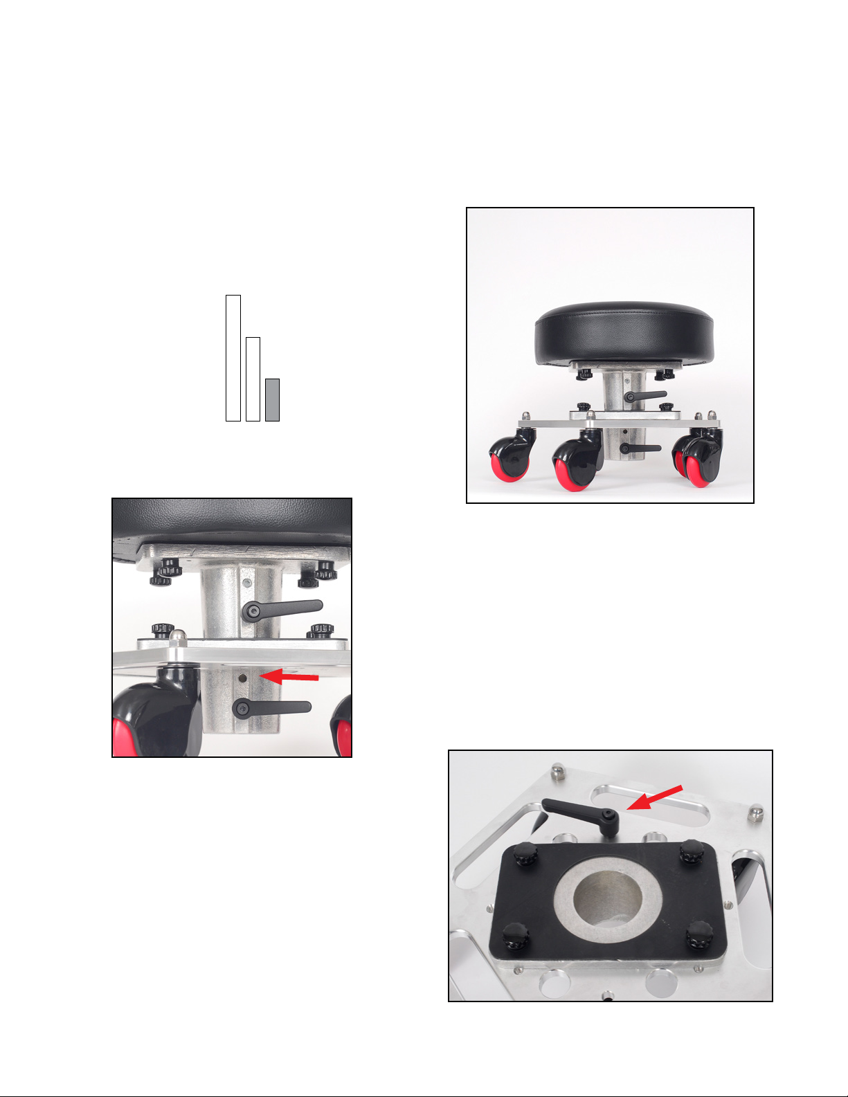
BUILD 3A - Low Mode 1
Build 3A
A 6” Center Pipe is used and the
Base Flange is mounted inverted.
This build places the seat 3 inches lower
than the lowest Standard-mode build.
* Note: It is necessary to temporarily
remove the lower Kipp handle from
the Base Flange in order for it to t
through the bottom of the Sneaker Base.
(see red arrow) Only 1 Kipp handle is used in
the Base Flange when installed inverted.
The un-used Kipp handle can be stored
in the 3/8” hole on the base as shown.
7

In this build, the seat and seat ange rest
rmly atop the Sneaker Base, but they are not
directly attached. This is to achieve a super quick
changeover. The seat can be lifted straight o the
Base. To FASTEN the seat directly to the Sneaker
Base, please refer to Build 3C on the next page.
Build 3B
Step 1: Remove the Base Flange
from the Sneaker Base (Figure 1).
Then screw two Knobs completely down into the
two threaded holes indicated in (Figure 1). The function
of this knob placement is to keep the seat from
rocking side to side.
Step 2: Remove any pipe from Seat Flange. Then thread
the Kipp Handle ( Figure 2) all the way in until it no
longer swivels. This is done to prevent the Kipp Handle
from dangling freely under the Sneaker base.
Step 3: Align the four Knobs of the Seat Flange (Figure 2)
with the four large holes in the Sneaker Base (Figure 3).
Then simply drop the seat into position on the base
BUILD 3B - Low Mode 2
(Fig. 1)
(Fig. 2) (Fig. 3)
8

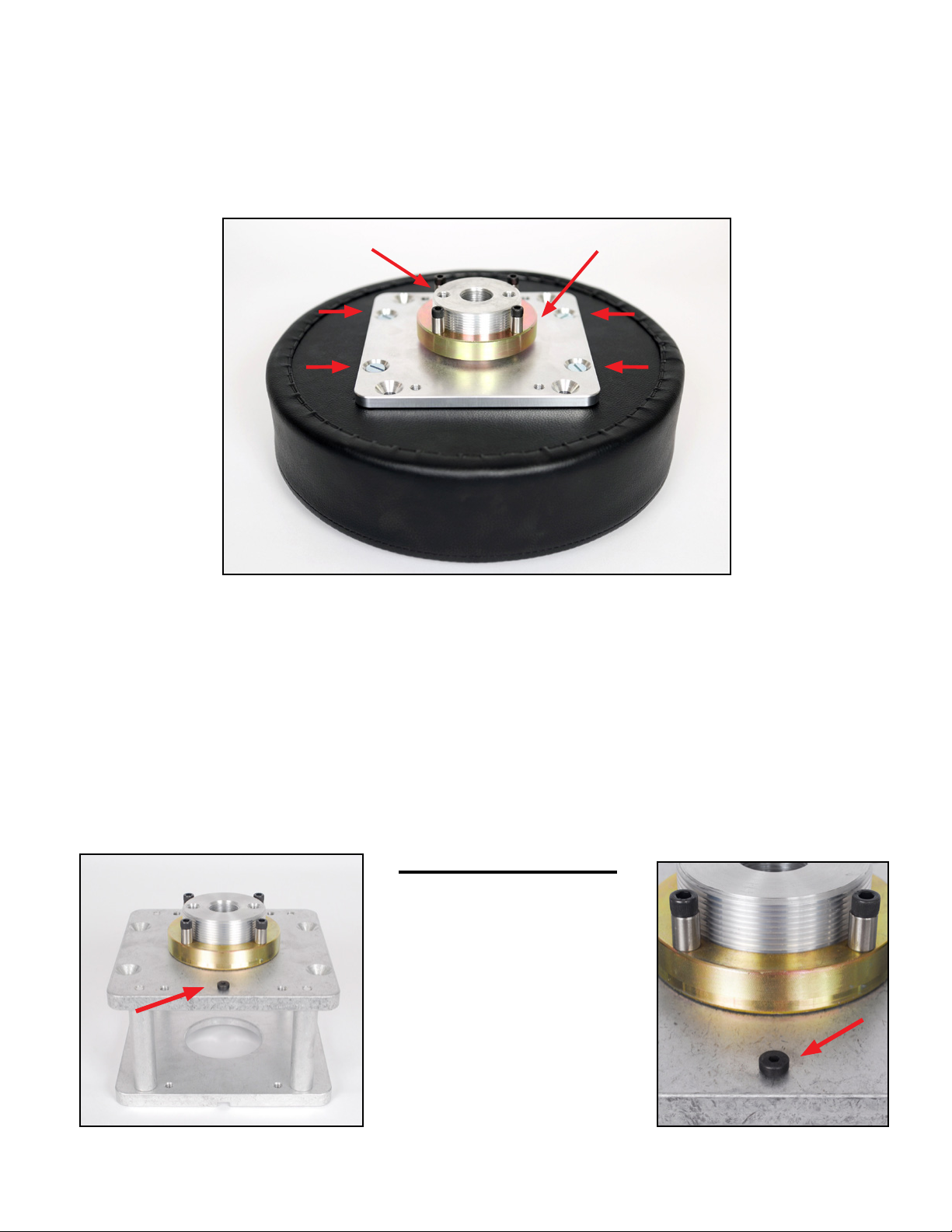
BUILD 3C - Low Mode 3
Build 3C
This build allows the seat to be FASTENED
directly to the Sneaker Base. It’s also the
lowest conguration of the Sneaker Dolly.
1/2 inch lower than Low Mode Build 4A.
No pipes or anges are used in this setup.
Step 1: Remove the Seat Flange and lay the
seat upside down on a at surface (Fig. 1).
Step 2: Remove the Base Flange from the
Sneaker Base and locate the two 3/8”
non-threaded through-holes (Fig. 2).
They are the only two small non-threaded
holes on the Base.
Step 3: Lay the Sneaker Base on top of the seat,
wheels facing up. Center the Base then rotate to
line up the two through-holes with two thread-
ed inserts in the seat. Then use two Knobs to
attach Seat to the Base (Fig. 3). Only 2 knobs are
used in this build.
(Fig. 1)
(Fig. 2)
(Fig. 3)
9

BUILD 4 - Mitchell High Mode
Build 4
By replacing the Sneaker Seat with the Mitchell
Block, you now have a rolling Mitchell Base.
There are 4 threaded 5/16”holes in the Mitchell
Block Bottom Plate. Use these holes and 4 Knobs
to attach the the Mitchell Block to the Seat Flange.
From here, use the various Center Pipes to adjust
your heights the same as you would in Seat Mode.
To go lower than 14 inches, refer to Build 5 and 6
Mitchell Low Modes on the next page.
Important Note: It is not recommonded to setup higher
than shoulder level in this conguration. Clearly, in this
build, the center of gravity and mass of the camera sit
high on a narrow base and can tip over if not careful.
For this reason it’s highly advisable that whenever built
in high Mitchell Mode, someone remain close to the
camera at all times and common sense is exercised.
10

BUILD 5 and 6 - Mitchell Low Modes
11
Build 5
This setup puts the height of the Mitchell base at
8” from the ground.
Step 1: Remove both Pipe anges from the
Sneaker Base and the Mitchell Block.
Step 2: Locate the 4 non-threaded holes in
the Mitchell Block Bottom Plate. And line them
up with 4 threaded 5/16”holes in Sneaker Base.
Step 3: Use 2 or 4 Knobs to fasten the Mitchell
Block directly to the Sneaker Base.
Build 6
This setup puts the height of the Mitchell
base at 5”. It’s basically a rolling hi-hat.
Step 1: Remove both Pipe anges from the
Sneaker Base and the Mitchell Block.
Step 2: Detach the Mitchell Top Plate from the
Mitchell Block by removing the four 5/16”
screws from the Mitchell Plate.
Step 3: Use the screws to attach the Mitchell Top
Plate to threaded 5/16”holes on Sneaker Base
Step 3 Alternate: Instead of using the athead
screws. The Mitchell Top Plate can be attached from
underneath the Sneaker Base using two knobs.
This setup adds a Mitchell Base to the Sneaker Seat. Mount it to a dolly boom arm,
a dolly oset, a vehicle rig or any special conguration you can dream up.
BUILD 7 - Mitchell Mount Seat
Build 7
Step 1: Remove the Seat Flange and Knobs from
the Sneaker Seat.
Step 2: Dis-assemble the Mitchell Block and
remove the Mitchell Bottom Plate.
Step 3: The Mitchell Kit includes a Mitchell
Thread and Castle Nut. Use the two at-head
3/8“ screws to attach the Mitchell Thread to
the Mitchell Bottom Plate.
Step 4: Attach the Mitchell Bottom Plate with
Thread to the Sneaker Seat using four 5/16”
at-head screws included in the Mitchell Kit.
The Mitchell Block can also be
used as a 4” riser. Simply
thread the Keyway Screw into
the 1/4”-28 hole as pictured.
The Keyway Screw can also be
used in Mitchell Seat mode,
although not very necessary
for most applications.
5/16”
screws
5/16”
screws
Mitchell Thread Castle Nut
Mitchell Bottom Plate
12

BUILD 8 - Pneumatic Mode
Build 8
The Pneumatic Kit provides 6 inches of height range using the
adjustment lever and gas lift. Remove the Seat Flange from the
seat and replace with the Pneumatic assembly.
There are four 3-inch riser posts included with the Pneumatic
Kit. These risers are optional for use in hydraulic mode. They
raise the Base Flange to add 3 inches of height on the top end
while keeping the same low end height. This build gives the
user 15 inches of range up and down without switching pipes.
13
30”
15”
Table of contents


