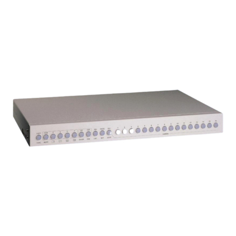
Snell Advanced Media IQMUX34 Operator's manual

www.s-a-m.com
User Instruction Manual
IQMUX34
3G/HD/SD-SDI Multiplexer for 8 Analog Channels

IQMUX34 Information and Notices
Issue 1 Rev 5 Page 2 © 2018 SAM
Information and Notices
Copyright and Disclaimer
Copyright protection claimed includes all forms and matters of copyrightable material and
information now allowed by statutory or judicial law or hereinafter granted, including without
limitation, material generated from the software programs which are displayed on the screen
such as icons, screen display looks etc.
Information in this manual and software are subject to change without notice and does not
represent a commitment on the part of SAM. The software described in this manual is
furnished under a license agreement and can not be reproduced or copied in any manner
without prior agreement with SAM or their authorized agents.
Reproduction or disassembly of embedded computer programs or algorithms prohibited.
No part of this publication can be transmitted or reproduced in any form or by any means,
electronic or mechanical, including photocopy, recording or any information storage and
retrieval system, without permission being granted, in writing, by the publishers or their
authorized agents.
SAM operates a policy of continuous improvement and development. SAM reserves the right
to make changes and improvements to any of the products described in this document
without prior notice.
Contact Details
For details of our Regional Customer Support Offices, please visit the SAM website and
navigate to Support/Contact Support.
www.s-a-m.com/support/contact-support/
Customers with a support contract should call their personalized number, which can be found
in their contract, and be ready to provide their contract number and details.

IQMUX34 Contents
Issue 1 Rev 5 Page 3 © 2018 SAM
Contents
Information and Notices . . . . . . . . . . . . . . . . . . . . . . . . . . . . . . . . . . . . . . . . . . . . . . . . 2
Copyright and Disclaimer . . . . . . . . . . . . . . . . . . . . . . . . . . . . . . . . . . . . . . . . . . . . . . 2
Contact Details . . . . . . . . . . . . . . . . . . . . . . . . . . . . . . . . . . . . . . . . . . . . . . . . . . . . . . 2
1. Introduction. . . . . . . . . . . . . . . . . . . . . . . . . . . . . . . . . . . . . . . . . . . . . . . . . . . . . . . . . 5
1.1 Description . . . . . . . . . . . . . . . . . . . . . . . . . . . . . . . . . . . . . . . . . . . . . . . . . . . . . . 5
1.2 Block Diagram . . . . . . . . . . . . . . . . . . . . . . . . . . . . . . . . . . . . . . . . . . . . . . . . . . . . 5
1.3 Feature Summary . . . . . . . . . . . . . . . . . . . . . . . . . . . . . . . . . . . . . . . . . . . . . . . . . 5
1.4 Order Codes . . . . . . . . . . . . . . . . . . . . . . . . . . . . . . . . . . . . . . . . . . . . . . . . . . . . . 6
1.5 Rear Panel View . . . . . . . . . . . . . . . . . . . . . . . . . . . . . . . . . . . . . . . . . . . . . . . . . . 6
1.6 Enclosures. . . . . . . . . . . . . . . . . . . . . . . . . . . . . . . . . . . . . . . . . . . . . . . . . . . . . . . 7
1.6.1 B-style Enclosure . . . . . . . . . . . . . . . . . . . . . . . . . . . . . . . . . . . . . . . . . . . . . 7
1.6.2 A-style Enclosures. . . . . . . . . . . . . . . . . . . . . . . . . . . . . . . . . . . . . . . . . . . . . 7
2. Technical Specification . . . . . . . . . . . . . . . . . . . . . . . . . . . . . . . . . . . . . . . . . . . . . . . 8
3. Connections . . . . . . . . . . . . . . . . . . . . . . . . . . . . . . . . . . . . . . . . . . . . . . . . . . . . . . . 11
3.1 SDI Inputs . . . . . . . . . . . . . . . . . . . . . . . . . . . . . . . . . . . . . . . . . . . . . . . . . . . . . . .11
3.2 SDI Outputs. . . . . . . . . . . . . . . . . . . . . . . . . . . . . . . . . . . . . . . . . . . . . . . . . . . . . .11
3.3 Analog Audio Input - D-Type . . . . . . . . . . . . . . . . . . . . . . . . . . . . . . . . . . . . . . . . .11
3.4 Analog Audio Input - Screw Terminals . . . . . . . . . . . . . . . . . . . . . . . . . . . . . . . . 12
4. Card Edge LEDs . . . . . . . . . . . . . . . . . . . . . . . . . . . . . . . . . . . . . . . . . . . . . . . . . . . . 13
5. Controlling the IQMUX34 from the RollCall Control Panel. . . . . . . . . . . . . . . . . . 14
5.1 Information Window. . . . . . . . . . . . . . . . . . . . . . . . . . . . . . . . . . . . . . . . . . . . . . . 14
5.1.1 Video Status . . . . . . . . . . . . . . . . . . . . . . . . . . . . . . . . . . . . . . . . . . . . . . . . 14
5.1.2 Audio Input Status . . . . . . . . . . . . . . . . . . . . . . . . . . . . . . . . . . . . . . . . . . . . 14
5.2 Video . . . . . . . . . . . . . . . . . . . . . . . . . . . . . . . . . . . . . . . . . . . . . . . . . . . . . . . . . . 15
5.2.1 Input Select . . . . . . . . . . . . . . . . . . . . . . . . . . . . . . . . . . . . . . . . . . . . . . . . . 15
5.2.2 Valid Input Standards . . . . . . . . . . . . . . . . . . . . . . . . . . . . . . . . . . . . . . . . . 15
5.2.3 Default Output . . . . . . . . . . . . . . . . . . . . . . . . . . . . . . . . . . . . . . . . . . . . . . . 16
5.2.4 Default Output Standard . . . . . . . . . . . . . . . . . . . . . . . . . . . . . . . . . . . . . . . 16
5.2.5 Blanking . . . . . . . . . . . . . . . . . . . . . . . . . . . . . . . . . . . . . . . . . . . . . . . . . . . 16
5.2.6 Freeze . . . . . . . . . . . . . . . . . . . . . . . . . . . . . . . . . . . . . . . . . . . . . . . . . . . . . 16
5.3 Procamp . . . . . . . . . . . . . . . . . . . . . . . . . . . . . . . . . . . . . . . . . . . . . . . . . . . . . . . 17
5.3.1 Procamp Enable . . . . . . . . . . . . . . . . . . . . . . . . . . . . . . . . . . . . . . . . . . . . . 17
5.3.2 Black Level . . . . . . . . . . . . . . . . . . . . . . . . . . . . . . . . . . . . . . . . . . . . . . . . . 17
5.3.3 Hue Adjust. . . . . . . . . . . . . . . . . . . . . . . . . . . . . . . . . . . . . . . . . . . . . . . . . . 17
5.3.4 Master Video Gain. . . . . . . . . . . . . . . . . . . . . . . . . . . . . . . . . . . . . . . . . . . . 18
5.3.5 Y Gain . . . . . . . . . . . . . . . . . . . . . . . . . . . . . . . . . . . . . . . . . . . . . . . . . . . . . 18
5.3.6 Cb/Cr Gain . . . . . . . . . . . . . . . . . . . . . . . . . . . . . . . . . . . . . . . . . . . . . . . . . 18
5.3.7 Y/C Timing. . . . . . . . . . . . . . . . . . . . . . . . . . . . . . . . . . . . . . . . . . . . . . . . . . 18
5.3.8 Picture Position . . . . . . . . . . . . . . . . . . . . . . . . . . . . . . . . . . . . . . . . . . . . . . 18
5.4 Video Delay . . . . . . . . . . . . . . . . . . . . . . . . . . . . . . . . . . . . . . . . . . . . . . . . . . . . . 19
5.4.1 Horizontal Delay . . . . . . . . . . . . . . . . . . . . . . . . . . . . . . . . . . . . . . . . . . . . . 19
5.4.2 Vertical Delay . . . . . . . . . . . . . . . . . . . . . . . . . . . . . . . . . . . . . . . . . . . . . . . 19
5.4.3 Frame Delay Added . . . . . . . . . . . . . . . . . . . . . . . . . . . . . . . . . . . . . . . . . . 19
5.4.4 Active Video Delay . . . . . . . . . . . . . . . . . . . . . . . . . . . . . . . . . . . . . . . . . . . 19
5.5 Embedder 1 to Embedder 4 . . . . . . . . . . . . . . . . . . . . . . . . . . . . . . . . . . . . . . . . 20
5.5.1 Embedder N Enable . . . . . . . . . . . . . . . . . . . . . . . . . . . . . . . . . . . . . . . . . . 20
5.5.2 Pair 1 and Pair 2 Controls . . . . . . . . . . . . . . . . . . . . . . . . . . . . . . . . . . . . . . 21
5.6 Router Overview . . . . . . . . . . . . . . . . . . . . . . . . . . . . . . . . . . . . . . . . . . . . . . . . . 22
5.7 Audio . . . . . . . . . . . . . . . . . . . . . . . . . . . . . . . . . . . . . . . . . . . . . . . . . . . . . . . . . . 23
5.7.1 Delays . . . . . . . . . . . . . . . . . . . . . . . . . . . . . . . . . . . . . . . . . . . . . . . . . . . . . 23
5.7.2 Manual Coarse and Manual Fine Delay Controls . . . . . . . . . . . . . . . . . . . . 23
5.7.3 Tone . . . . . . . . . . . . . . . . . . . . . . . . . . . . . . . . . . . . . . . . . . . . . . . . . . . . . . 23

IQMUX34 Contents
Issue 1 Rev 5 Page 4 © 2018 SAM
5.7.4 Audio Monitor . . . . . . . . . . . . . . . . . . . . . . . . . . . . . . . . . . . . . . . . . . . . . . . 24
5.8 Analog Setup. . . . . . . . . . . . . . . . . . . . . . . . . . . . . . . . . . . . . . . . . . . . . . . . . . . . 25
5.8.1 Headroom . . . . . . . . . . . . . . . . . . . . . . . . . . . . . . . . . . . . . . . . . . . . . . . . . . 25
5.9 Pattern & Caption . . . . . . . . . . . . . . . . . . . . . . . . . . . . . . . . . . . . . . . . . . . . . . . . 26
5.9.1 Edit Caption. . . . . . . . . . . . . . . . . . . . . . . . . . . . . . . . . . . . . . . . . . . . . . . . . 26
5.9.2 Select Caption. . . . . . . . . . . . . . . . . . . . . . . . . . . . . . . . . . . . . . . . . . . . . . . 26
5.9.3 Pattern Select . . . . . . . . . . . . . . . . . . . . . . . . . . . . . . . . . . . . . . . . . . . . . . . 26
5.10 Memories. . . . . . . . . . . . . . . . . . . . . . . . . . . . . . . . . . . . . . . . . . . . . . . . . . . . . . 27
5.10.1 Recall Memory . . . . . . . . . . . . . . . . . . . . . . . . . . . . . . . . . . . . . . . . . . . . . 27
5.10.2 Save Memory . . . . . . . . . . . . . . . . . . . . . . . . . . . . . . . . . . . . . . . . . . . . . . 27
5.10.3 Last Recalled Memory. . . . . . . . . . . . . . . . . . . . . . . . . . . . . . . . . . . . . . . . 28
5.10.4 Save Memory Name . . . . . . . . . . . . . . . . . . . . . . . . . . . . . . . . . . . . . . . . . 28
5.11 Logging . . . . . . . . . . . . . . . . . . . . . . . . . . . . . . . . . . . . . . . . . . . . . . . . . . . . . . . 29
5.11.1 Logging Misc . . . . . . . . . . . . . . . . . . . . . . . . . . . . . . . . . . . . . . . . . . . . . . . 29
5.11.2 Logging Video Input 1 and 2 . . . . . . . . . . . . . . . . . . . . . . . . . . . . . . . . . . . 29
5.11.3 Logging Audio Input 1 and 2 . . . . . . . . . . . . . . . . . . . . . . . . . . . . . . . . . . . 30
5.11.4 Logging Video Output . . . . . . . . . . . . . . . . . . . . . . . . . . . . . . . . . . . . . . . . 30
5.11.5 Logging Audio Output . . . . . . . . . . . . . . . . . . . . . . . . . . . . . . . . . . . . . . . . 30
5.11.6 Log Field Descriptions . . . . . . . . . . . . . . . . . . . . . . . . . . . . . . . . . . . . . . . . 31
5.12 RollTrack . . . . . . . . . . . . . . . . . . . . . . . . . . . . . . . . . . . . . . . . . . . . . . . . . . . . . . 33
5.12.1 Disable All . . . . . . . . . . . . . . . . . . . . . . . . . . . . . . . . . . . . . . . . . . . . . . . . . 33
5.12.2 RollTrack Index . . . . . . . . . . . . . . . . . . . . . . . . . . . . . . . . . . . . . . . . . . . . . 33
5.12.3 RollTrack Source. . . . . . . . . . . . . . . . . . . . . . . . . . . . . . . . . . . . . . . . . . . . 33
5.12.4 RollTrack Address . . . . . . . . . . . . . . . . . . . . . . . . . . . . . . . . . . . . . . . . . . . 33
5.12.5 RollTrack Command . . . . . . . . . . . . . . . . . . . . . . . . . . . . . . . . . . . . . . . . . 34
5.12.6 RollTrack Sending . . . . . . . . . . . . . . . . . . . . . . . . . . . . . . . . . . . . . . . . . . 34
5.12.7 RollTrack Status . . . . . . . . . . . . . . . . . . . . . . . . . . . . . . . . . . . . . . . . . . . . 34
5.13 Status . . . . . . . . . . . . . . . . . . . . . . . . . . . . . . . . . . . . . . . . . . . . . . . . . . . . . . . . 35
5.13.1 Factory Defaults . . . . . . . . . . . . . . . . . . . . . . . . . . . . . . . . . . . . . . . . . . . . 35
5.13.2 Default Settings. . . . . . . . . . . . . . . . . . . . . . . . . . . . . . . . . . . . . . . . . . . . . 35
5.13.3 Restart. . . . . . . . . . . . . . . . . . . . . . . . . . . . . . . . . . . . . . . . . . . . . . . . . . . . 35

IQMUX34 Introduction
Issue 1 Rev 5 Page 5 © 2018 SAM
1. Introduction
1.1 Description
The IQMUX34 provides 4 or 8-channel analog audio multiplexing for HD-SDI 3 Gbit/s, 1.5
Gbit/s, or 270 Mbit/s SD-SDI signals. Audio processing features include audio delay, gain,
invert, and channel level routing, while video delay and a video proc. amp are also included in
the feature-set.
1.2 Block Diagram
1.3 Feature Summary
• 4/8-channel 3G/HD/SD-SDI multiplexer for analog audio inputs - via 25-way D-Type
(8-channel) or screw terminals (4-channel)
• Standards supported:
• 3G-SDI to SMPTE 424M/425M level A & B compatible
• HD-SDI to SMPTE292M/274M/296M
• SD-SDI to SMPTE259M-C
• Handles up to 16 channels of embedded audio present on the incoming SDI stream.
• Includes independent gain, invert, mute controls, channel level (sub-frame) routing,
and adjustable delay for selected audio channels.
• Embedding continues on loss of SDI input (silence).
• Any group of embedded audio may be passed unchanged, processed, or blanked.
• Embedded Dolby E support – pair routing and delay.
• Up to nine frames of video delay and two seconds of audio delay.
• Video controls including video gain, offset, HANC and VANC blanking control.
• Input loss detection – default output of black/pattern.
• Transparent to all ancillary data inc. VANC metadata.
• In-built test pattern generator and audio tone generator.
• 16 user memories, save/recall/rename.
• Rollcall control and monitoring compatible.

IQMUX34 Introduction
Issue 1 Rev 5 Page 6 © 2018 SAM
1.4 Order Codes
The following product order codes are covered by this manual:
1.5 Rear Panel View
The following rear panel types are available:
Note:
Modules with “A” order codes (for example, IQMUX3449-1A3) can be fitted into either A- or
B-style enclosures. Modules with “B” order codes (for example, IQMUX3449-1B3) can only
be fitted into B-style enclosures. See page 7.
IQMUX3449-1A3
IQMUX3449-1B3
3G/HD/SD-SDI 8-channel analog audio multiplexer. 2 SDI inputs, 2 SDI
outputs, 8 balanced analog audio inputs.
IQMUX3451-1A
IQMUX3451-1B
3G/HD/SD-SDI 4-channel analog audio multiplexer. 2 SDI inputs, 2 SDI
outputs, 4 balanced analog audio screw terminal inputs.

IQMUX34 Introduction
Issue 1 Rev 5 Page 7 © 2018 SAM
1.6 Enclosures
The module can be fitted into the enclosure types shown.
1.6.1 B-style Enclosure
Enclosure order codes: IQH3B-S-0, IQH3B-S-P
1.6.2 A-style Enclosures
Enclosure order code: IQH1A-S-P
Enclosure order codes: IQH3A-S-0, IQH3A-S-P
Enclosure order codes: IQH3A-E-0, IQH3A-E-P, IQH3A-0-0, IQH3A-0-P
Enclosure order code: IQH1A-S-P
Important:
Although IQ modules are interchangeable between enclosures, their rear panels are
enclosure specific. An IQH3B enclosure accepts modules with either “A” or “B” order
codes. An IQH3A or IQH1A enclosure accepts modules with “A” order codes only. See
page 6.

IQMUX34 Technical Specification
Issue 1 Rev 5 Page 8 © 2018 SAM
2. Technical Specification
Inputs and Outputs
Signal Inputs
SDI Inputs x 2
Input 1 Cable Length Up to 70 m Belden 1694A @ 3 Gbit/s
Up to 160 m Belden 1694A @ 1.5 Gbit/s
>350 m Belden 1694A @ 270 Mbit/s
Input 2 Cable Length Up to 60 m Belden 1694A @ 3 Gbit/s
Up to 100 m Belden 1694A @ 1.5 Gbit/s
Up to 100 m Belden 1694A @ 270 Mbit/s
Audio Signal Inputs
Balanced Analog Audio Inputs 8 channels (25-Way D-Type)
Signal Outputs
SDI Outputs x 2
Controls
Indicators
Power OK (green)
CPU running OK (green flashing)
FPGA running OK (green flashing)
Status OK (green)
Warning (yellow)
Error (red)
Input 1 OK (green)
Input 2 OK (green)
Video Controls
Input Standard 1125(1080)/50P (A & B), 1125(1080)/59P (A & B),
1125(1080)/29i, 1125(1080)/25i,
750(720)/59P, 750(720)/50P,
525(480)/29i, 625(576)/25i
Default Video Output Type Pattern, Freeze, Black
Default Video Output Standard Last Known Good,
1125(1080)/50P (A & B), 1125(1080)/59P (A & B),
1125(1080)/29i, 1125(1080)/25i,
750(720)/59P, 750(720)/50P,
525(480)/29i, 625(576)/25i
Video Select Input 1, Input 2
Audio Select Video Input 1, Video Input 2, Follow Video
Manual Freeze On/Off
Freeze Field/Frame
Video Delay Frames 0 to 9 F
VANC Data Blank VANC
SD VANC Data Line blanking (6 controls)
ProcAmp Enable On/Off

IQMUX34 Technical Specification
Issue 1 Rev 5 Page 9 © 2018 SAM
Black Level ±100 mV in steps of 0.8 mV
Hue Adjust ±180 in steps of 1
Master Video Gain ±6 dB in steps of 0.1 dB
Y-Gain ±6 dB in steps of 0.1 dB
Cb/Cr Gain ±6 dB in steps of 0.1 dB
Y/C Timing ±8 pixels in 2 pixel steps (SD)
±16 pixels in 2 pixel steps (HD/3G)
Picture Position ±8 pixels in 2 pixel steps (SD)
±16 pixels in 2 pixel steps (HD/3G)
Pattern On On/Off
Pattern Select 75% Color Bars, Black
Caption On On/Off
Edit Caption 19 characters available
Audio Controls
Embedder Assignment
Group 1 to 4 Enable On/Off
Pair 1 to 8 Source L Dis-embed 1_1 to 8_2, Analog 1 to 8, Tone, Silence
Pair 1 to 8 Source R Dis-embed 1_1 to 8_2, Analog 1 to 8, Tone, Silence
Pair 1 to 8 Stereo Link channel pairs
Pair 1 to 8 Polarity L/R On/Off
Pair 1 to 8 Gain L/R +12 dB to -72 dB in 0.1 dB steps
Pair 1 to 8 Non-PCM On/Off
Processed Audio Delay Control
Coarse Manual Delay Up to 1.75 s in 5 ms steps
Fine Manual Delay ± 0.25 s in 0.5 ms steps
Tone
Frequency L/R 100 Hz to 10 kHz in 100 Hz steps
Channel Ident On/Off
HANC Data Blank HANC (Removes all HANC data, including audio, when embedders
disabled)
Audio Monitoring
Silence Detect 0 to -80 dB in steps of 1 dB
Signal Overload Detect 0 to -80 dB in steps of 1 dB
Warning Timer 1 to 20 seconds in steps of 1 second
Audio Setup Controls
Analog Headroom +12 dBU to +24 dBU
Note: Headroom level specified at 0 dBFS line-up level
Other Controls
User Memories 16x Save, Recall, Rename
Memory Naming User configurable naming of memories 1–16

IQMUX34 Technical Specification
Issue 1 Rev 5 Page 10 © 2018 SAM
RollTrack Sources Unused, Video Delay, Input Present, Input1 Select, Input2 Select, Input
Loss, Output 525, Output 625, Output 720p, Output 1080i, Output 1080p,
Output Freeze, Output Unfreeze, Output Pattern on, Output pattern off,
Output Caption on, Output Caption off, Disemb (Pairs 1–8) PCM, Disemb
(Pairs 1–8) Data, Disemb (Pairs 1–8) DolbyE, Disemb (Pairs 1–8) V bit,
Disemb (Pairs 1–8) Loss
Information Window Video Input Status, Audio Input Status
Factory Default Resets all module settings to factory specified default values and clears
memories
Default Settings Resets all module settings to factory specified defaults but does not clear
memories
Restart Software restart of the module
Module Information Reports following module information: Software version, Serial number,
Build number, KOS version, Firmware version, PCB version
Electrical 3 Gbit/s SDI, SMPTE 424M
1.5 Gbit/s HD-SDI, SMPTE 292M
270 Mbit/s SDI, SMPTE 259M-C/DVB-ASI
Connector/Format BNC/ 75 Ohm panel jack on standard IQ connector panel
Return Loss >-15 dB (270 Mbit/s, 1.5 Gbit/s)
>-10 dB (3 Gbit/s)
Output Jitter SD-SDI 0.2 UI (10 Hz)/0.2 UI (1 kHz)
3G/HD-SDI 1.0 UI (10 Hz)/0.2 UI (100 kHz)
Video Standards
Standards 1125(1080)/50p (A & B), 1125(1080)/59p (A & B),
750(720)/50p, 750(720)/59p,
1125(1080)/25i, 1125(1080)/29i,
625(576)/25i, 525(480)/29i
Typical Video Delay Typical delay (input lock with Dolby E alignment off): 2 lines
Typical delay (input lock with Dolby E alignment on): 1 frame
Embedded Audio Handling HD - 24-bit synchronous 48 kHz to SMPTE 299M
SD - 20-bit synchronous 48 kHz to SMPTE 272M-A
Embedded Audio Delay Minimum (PCM) 2 ms
Maximum (non-PCM)
SD: 67 µs
HD: 28 µs
3G-A: 15 µs
3G-B: 25 µs
Analog Audio Input (Balanced)
Analog Input Impedance 40 k ohms
Distortion (THD+N) -100 dB @ +2 dBU 800 Hz
Frequency Response 20 Hz to 20 KHz + 0.05 dB
Dynamic Range 114 dB typical
Power Consumption
Module Power Consumption 9 W (A Frames)
9PR(BFrames)

IQMUX34 Connections
Issue 1 Rev 5 Page 11 © 2018 SAM
3. Connections
This section describes the physical input and output connections provided by the IQMUX34.
3.1 SDI Inputs
3.2 SDI Outputs
3.3 Analog Audio Input - D-Type
Serial digital input to the unit is made by
means of two BNC connectors which
terminate in 75 Ohms.
Serial digital output from the unit is made by
means of two BNC connectors which
terminate in 75 Ohms.
Analog audio input to the unit can be made
by either a 25-way D-type connector or 4
screw terminals.
The table below details the pin connections.
Pin Connection Pin Connection
1 CHASSIS 14 8 OUT GND
2 8 OUT+ 15 8 OUT-
3 7 OUT+ 16 7 OUT-
4 7 OUT GND 17 6 OUT GND
5 6 OUT+ 18 6 OUT-
6 5 OUT+ 19 5 OUT-
7 5 OUT GND 20 4 OUT GND
8 4 OUT+ 21 4 OUT-
9 3 OUT+ 22 3 OUT-
10 3 OUT GND 23 2 OUT GND
11 2 OUT+ 24 2 OUT-
12 1 OUT+ 25 1 OUT-
13 1 OUT GND
1
14
13
25

IQMUX34 Connections
Issue 1 Rev 5 Page 12 © 2018 SAM
3.4 Analog Audio Input - Screw Terminals
Analog audio input to the unit can be made
by either a 25-way D-type connector or 4
screw terminals.
Negative Positive
GND

IQMUX34 Card Edge LEDs
Issue 1 Rev 5 Page 13 © 2018 SAM
4. Card Edge LEDs
The LEDs on the edge of the module indicate its operating status.
POWER
+
POWER
-
CPU
OK
FPGA
OK
ERR WARN OK
IN1 IN2 REF
LED Color State Indication
POWER + Green Illuminated A positive power supply is present.
POWER - Green Illuminated A negative power supply is present.
CPU OK Green Flashing The CPU is running.
FPGA OK Green Illuminated The unit is booting. LED stays illuminated until the
SDI is enabled.
Green Flashing The FPGA is running.
IN 1 & IN 2 Green Illuminated A valid input is present.
REF Green Illuminated A valid reference signal is present.
Green Flashing An incorrect frame rate reference is present.
ERR Red Illuminated Board fault conditions. When the module is
booting, this LED is illuminated until the SDI is
enabled.
WARN Yellow Illuminated Board warning conditions. LED is illuminated when
one or more of the SDI inputs is not valid.
OK Green Illuminated The module is operating correctly.

IQMUX34 Controlling the IQMUX34 from the RollCall Control Panel
Issue 1 Rev 5 Page 14 © 2018 SAM
5. Controlling the IQMUX34 from the RollCall Control Panel
5.1 Information Window
The Information Window is in the upper-right corner of each screen and displays basic
information about the input and output status of the module.
5.1.1 Video Status
When Video Status is selected, the Information Window displays the following information:
5.1.2 Audio Input Status
When Audio Input Status is selected, the Information Window displays the following
information:
Name Status Description Standard
IN1: OK
FAIL
LOST
MISM
Input signal received
Input signal failed
No signal received
Mismatch format detected
Detected video input standard is
displayed, for example, 1080/50p
(Blank if input lost).
IN2:
OUT: OK
BLK
FRZ
PAT
Output signal delivered
Black output delivered
Frozen output delivered
Pattern output delivered
Selected video output standard is
displayed, for example, 1080/50p.
A $ symbol indicates that the caption
is enabled. (Blank if disabled).
Name Status Description
Audio Embed Input P
?
D
E
V
Channel is a PCM audio input.
No audio input is detected.
Signal is data (non-PCM, Dolby, etc.).
Signal is Dolby E.
V bit present on audio channel.
--------
Audio AES Input
--------

IQMUX34 Controlling the IQMUX34 from the RollCall Control Panel
Issue 1 Rev 5 Page 15 © 2018 SAM
5.2 Video
The Video screen enables you to specify the following settings for the selected serial data
input:
• Valid input standards
• The default output standard
• Any required ancillary blanking
• Freeze options on the output image
• The default output
5.2.1 Input Select
The Input Select control selects either Input 1 (at connector SER IN 1) or Input 2 (at
connector SER IN 2) to be processed by the module.
5.2.2 Valid Input Standards
The Valid Input Standards check boxes specify the video input standards that the module
will accept. The module will automatically detect the standard of the received input and block
any signal that does not comply with these selected video formats.
By default, all input standards are selected.

IQMUX34 Controlling the IQMUX34 from the RollCall Control Panel
Issue 1 Rev 5 Page 16 © 2018 SAM
5.2.3 Default Output
The Default Output control specifies the module’s output in the event of signal loss at the
input. Options are:
•Black: video out is a black screen.
•Freeze: video output is frozen/paused.
•Pattern: video output is a pre-determined test pattern or information screen.
5.2.4 Default Output Standard
The Default Output Standard settings specify the output standard that the module will use if
it cannot determine the correct output standard to use.
By default, the Last Known Good setting is selected, which uses the last valid output
standard.
5.2.5 Blanking
The Blanking controls enable specific lines of VANC to be blanked.
•625 blank lines: Applied to 625 only, you can blank either or both of line 23 or line
336.
•525 blank lines: Applied to 525 only, you can blank any or all of lines 21, 22, 283, or
284.
•Blank VANC: Selecting this option blanks the following lines inclusively:
All VANC data from the end of the last active video line to the end of the RP168 switch
line is always blanked, irrespective of this control.
•Blank HANC: Selecting this option removes all horizontal ancillary data including
audio when the embedders are disabled and the audio is unprocessed.
5.2.6 Freeze
The Manual Freeze control freezes/pauses the output. Freeze type can be specified as either
Field or Frame.
525: 11–20, 274–282
625: 7–22, 320–335
720: 8–25
1080i: 8-20, 570–583
1080P: 8–41
Note:
This function is disabled on a power-cycle of the module.

IQMUX34 Controlling the IQMUX34 from the RollCall Control Panel
Issue 1 Rev 5 Page 17 © 2018 SAM
5.3 Procamp
The Procamp screen enables the following processing amplifier settings to be adjusted:
• Black Level
• Hue Adjust
• Master Video Gain
• Y Gain (Luma)
• Cb/Cr Gain (Chroma)
• Y/C Timing
• Picture position
5.3.1 Procamp Enable
The Procamp Enable check box enables the video processing amplifier functions. Clear the
check box to disable the Procamp functions.
5.3.2 Black Level
The Black Level control allows the channel’s black level to be adjusted over a range of ±100
mV in steps of 0.8 mV. The preset value is 0.
5.3.3 Hue Adjust
The Hue Adjust control allows the channel’s hue to be adjusted over a range of ±180° in
steps of 1°. The preset value is 0.

IQMUX34 Controlling the IQMUX34 from the RollCall Control Panel
Issue 1 Rev 5 Page 18 © 2018 SAM
5.3.4 Master Video Gain
The Master Video Gain control allows the video gain to be adjusted over a range of ±6 dB in
steps of 0.1 dB. The preset value is 0.
5.3.5 Y Gain
The Y Gain control allows the luma to be adjusted over a range of ±6 dB in steps of 0.1 dB.
The preset value is 0.
5.3.6 Cb/Cr Gain
The Cb/Cr Gain control allows the chrominance to be adjusted over a range of ±6 dB in steps
of 0.1 dB. The preset value is 0.
5.3.7 Y/C Timing
The Y/C Timing control allows the luma/chroma timing to be adjusted over a range of:
• ± 8 pixels in 2 pixel steps in SD
• ± 16 pixels in 2 pixel steps in HD/3G
The preset value is 0.
5.3.8 Picture Position
The Picture Position control allows the picture position to be adjusted over a range of:
• ± 8 pixels in 2 pixel steps SD
• ± 16 pixels in 2 pixel steps HD/3G
The preset value is 0.

IQMUX34 Controlling the IQMUX34 from the RollCall Control Panel
Issue 1 Rev 5 Page 19 © 2018 SAM
5.4 Video Delay
The Video Delay screen enables the video delay mode to be specified.
5.4.1 Horizontal Delay
Use the slider bar to adjust the horizontal delay over a range of 0 to 1 line in 1 pixel steps. The
preset value is 0.
If the delay is set to lower than the latency, the delay will stop at the latency but this will not be
indicated. Additionally, if the vertical delay is set to 0, the lowest horizontal delay will equal the
latency of the module rather than the delay specified by this control.
5.4.2 Vertical Delay
Use the slider bar to add up to 1 frame of vertical delay in steps of 1 line. The preset value
is 0.
5.4.3 Frame Delay Added
You can specify up to nine additional frames of delay using this slider bar.
The delay of non-PCM audio, or ‘pass-through’ audio is also set by this control.
The delay, in ms, is displayed below this control.
5.4.4 Active Video Delay
The total active video delay (in ms) is displayed at the bottom of this screen.

IQMUX34 Controlling the IQMUX34 from the RollCall Control Panel
Issue 1 Rev 5 Page 20 © 2018 SAM
5.5 Embedder 1 to Embedder 4
Four embedder groups are provided. Each embedder group comprises two stereo audio
pairs, each of which has a left and right channel. The settings on these screens enable you to:
• Enable or disable the embedder group
• Apply a mute to a pair within the group
• Configure each pair as either 2 Channel, Stereo, or Non-PCM
• Configure each channel within the pair
• Specify the route for each channel
With the exception of the Embedder Enable control, each control is duplicated for Pair 1 and
Pair 2.
5.5.1 Embedder NEnable
This option, when checked, enables the embedder group.
Note:
The control templates for Embedder 1 to Embedder 4 comprise the same controls. To
avoid repetition, the controls are only described once in this manual.
Table of contents
Other Snell Advanced Media Multiplexer manuals
Popular Multiplexer manuals by other brands
ADTRAN
ADTRAN TSU 600 Product specifications
Measurement Computing
Measurement Computing CIO-EXP16 user guide
Juniper
Juniper TCX1000-2D8CMD quick start guide
Pickering
Pickering PXI 40-661A user manual
National Instruments
National Instruments NI PXI-2527 Specifications

Terahertz Technologies
Terahertz Technologies FM-1600 operating instructions
LINK-MI
LINK-MI LM-SH161 user manual
Kathrein
Kathrein UFO 20610040 Mounting instructions
American Fibertek
American Fibertek MTX-8229C instruction manual

Comnet
Comnet Value FVR81 Series Installation and operation manual
Sagem
Sagem ADR 155C Installation and user guide
American Dynamics
American Dynamics Multivision Quest DMV14Q Specifications
