Sno-Pro Fast-Cast 2000 (1CS1) User manual

®
™
Fast-Cast 2000 (1CS1), Fast-Cast 300 (1CS9), Fast-Cast 400 (1CS10)
1 of 17
FAST-CAST SERIES SPREADERS
Curtis Industries Inc. LLC, 111 Higgins St., Worcester, MA 01606 TEL: (800) 343-7676 FAX: (508) 854-3377 For Parts and information visit us at www.Curtisindustries.net
Curtis Industries Inc. LLC, reserves the right to change product design or specifications without notice or liability.
Assembly and Owner's Manual - September 2010

2 of 17
►Beforeattemptinganyprocedureinthismanual,thesesafetyinstructionsmustbereadandunder-
stoodbyallworkerswhohaveanypartinthepreparationoruseofthisequipment.
►Foryoursafety,warningandinformationdecalshavebeenafxedtothisproducttoremindall
operatorsofsafetyprecautions.Ifdecalsaremarked,damagedordestroyed,replacewithnewdecals
orderedfromCurtisIndustries,LLC.
1. Most accidents are preventable and caused by human error.
Exercise care and precautions to prevent the possibility of injury to operator or to others.
2. Never operate equipment when under the inuence of alcohol, drugs or medication that might
alter your judgement and / or reaction time.
3. Before working with the Spreader, secure all loose tting clothing and unrestrained hair.
4. Always wear safety glasses with side shields when working metal against metal. Failure to do
so could result in serious injury to the eyes.
5. Never allow children to operate or climb on equipment.
6. Never weld or grind on equipment without having a re extinguisher available.
7. Always check areas to be spread to be sure no hazardous conditions or substances are in the
area.
8. Always inspect unit for defects: Broken, worn or bent parts, weakened areas on Spreader or
Mount.
9. Always shut off vehicle and power source before attempting to attach or detach or service
Spreader unit. Be sure vehicle/power source is properly braked or chocked.
10. Always make sure personnel are clear of areas of danger when using equipment.
11. Always keep hands, feet, and clothing away from power-driven parts.
12. Remember, it is the owner’s responsibility to communicate information on safe usage and
proper maintenance of all equipment.
WARNING
IMPORTANT: Before you Start...
1CS9 ▪ Fast-Cast 300
• Rock Salt, Deicers
• Light Duty Grade Applications
• 3.0 Cu. ft./180 lb. Capacity
• 4 to 20 ft. Spreading Width
• 7-10 Amperage Draw
• Fine Material Applications
• 3.0 Cu. ft./180 lb. Capacity
• 4 to 20 ft. Spreading Width
• 7-10 Amperage Draw
1CS10 ▪ Fast-Cast 400

3 of 17
■ Never exceed 45 m.p.h. when loaded spreader is attached to vehicle. Braking distances may be
affected and handling characteristics may be impaired at speeds above 45 m.p.h.
■ Never use wet materials, or materials with foreign debris in the Fast-Cast Spreaders.
These units are designed to handle dry, clean, free-owing material.
Curtis Spreaders can not spread water softener salt.
■ Never leave material in Hopper for long periods of time. Be aware that all ice melters are
hygroscopic and will attract atmospheric moisture and harden up.
■ Always inspect pins, and latches whenever attaching or detaching Spreader, and before traveling.
■ Inspect the unit periodically for defects. Parts that are broken, missing, or worn out must be
replaced immediately. The unit, or any part of it should not be altered without prior written
permission from the manufacturer.
CAUTION
1CS1 ▪ Fast-Cast 2000
• Rock Salt, Deicers
• Free-Flowing Materials
• 5.0 Cu. ft./350 lb. Capacity
• 4 to 40 ft. Spreading Width
• 12-15 Amperage Draw
NOTE

1g. Installignitionwiretoanauxiliarycircuitthatishot
whentheignitionkeyisturnedtoONposition.This
wireis60"longandhasafemaleterminalattached
toit.ThiswirewillplugintobackofController.
ThiswiremustbeinstalledinorderforControllerto
operate.
1h.PushtheON/OFFbuttonontheControllertocheckfor
power,whenthathasbeenconrmedturnpowerOFF.
Theelectricalportionoftheinstallationiscomplete.
If adding an inline fuse,
use a 35 amp slow blow fuse
on Fast-Cast 2000 only.
SECTION 2. OPERATING THE SPREADER
2a. PREPARATION
Sweep area clear of foreign
objects or obstacles that could
cause personal injury.
Keep other persons, children,
or animals out of the area to
be spread.
2b. SPREADER LOADING
Do not overload vehicle. Rock
Salt weighs 35-40 pounds per
cubic foot.
Maximum weight of materials
for the Fast-Cast 2000 is
350 lbs. for a pickup truck,
and 250 lbs. for a UTV mounted
Spreader.
Always comply with
manufacturer’s maximum
gross vehicle weight ratings.
Never leave materials in
Hopper for long periods of
time as salt is hygroscopic
and will attract atmospheric
moisture and harden up.
4 of 17
Sno-Pro Fast-Cast Series Spreaders
NOTE
CAUTION
CAUTION
WARNING
SECTION 1. SPREADER WIRING STEPS
(Refer to Page 17)
1a. TheHarnessAssemblywillberoutedfromtherearof
thevehicletothefront.RouteHarnessalongframe
andattachtoframeholesandframesupports.
It is not recommended to
attach to fuel or brake lines
for obvious reasons.
Donotrouteclosetoexhaustsystemorengine,
eventhoughCurtisuseshightemperaturewiring,
thewiringcouldstillmeltunderextremeheatand
shortthespreaderelectricalsystem,aswellasthe
vehicleelectricalsystem.
1b. MountRearPlugonbumperusingsuppliedbolts.
Locatetowardsthecenterofthebumpertoreduce
theamountofdebristhetireswillthrowtotherear.
Apply a small amount of
dielectric grease to the plug.
1c.SecureHarnessfromthereartothefrontusing
heavydutytie-wrapsorframeclipsalongtheframe
andlighterdutytie-wrapsinallotherlocations.
1d. LayoutHarnessportionthatconnectstothebattery
alongtherewallandfenderwell.Donotconnect
powerleadstoBatteryatthistime.Drilla3/4"hole
intherewall,oruseexistingaccesshole,forthe
controlportionoftheHarnessandrouteconnector
andHarnessthroughhole.Besuretocheckthe
areaontheothersideoftherewalltobecertain
thatyouarenotgoingtodrillintothevehicleharness
oraControlModule.Generallyyoucandrilloneither
sideofthesteeringwheelforagoodlocation.
1e.ConnectHarnesstothebackoftheControllerand
mounttoasuitablelocation.
You may want to contact
customer before mounting
controller, some prefer not to
have holes drilled into the
dashboard.
Tie-wraplooseControllerHarnessandmoveto
thevehicleenginecompartment.
1f. Connectpowerleadstothe
Battery: Red (+) Positive, Black (–) Negative.
AlwaysconnecttotheprimaryBatteryifusingaDual
BatterySystem.Securelooseloomtoanyotherlarge
ormediumvehicleharnesswithmediumdutytie-
wraps;thiswillsecurewiringHarness.
WARNING
IMPORTANT
IMPORTANT
NOTE

Sno-Pro Fast-Cast Series Spreaders
5 of 17
2c. SPREADER LOADING TIPS
► Never exceed 10 m.p.h. when spreading.
► For a wider pass, increase Spinner speed.
► For a heavier pass, drive slower.
► Never operate Spreader near pedestrians.
► Spread ice melters with the storm to prevent
unmanageable levels of ice.
► Calculate spread pattern when near vegetation.
2d.FAST-CAST 2000 OPERATION
(1.) TheVariableSpeedControllerhasnger-tip
dialaction.
(2.) ToStart,pressPowerSwitchonControllerand
Spreaderwillacceleratetospeedsetondial.
(3.) ToStop,pressPowerSwitchonControllerto
offposition.
(4.) AdjustspeedofSpinnerbyusingdialonright
sideofController.
SECTION 3. FAST-CAST 400 ASSEMBLY
STEPS (Refer to Page 12)
3a. AttachHopperTubeSupport(17)toTransmission
Weldment(18)usingfour5/16"-18x1-3/4"HexBolts
(11)andfour5/16"LockNuts(3)Usethefourbottom
mountingholesatendsofHopperTubeSupport(17).
3b. LocateSpreaderGateDeck(15)andplaceupside
downonaatworksurface.
3c. AssembleGateIndicator/Stop(12)onStopSlidewith
GateKnob(7).GateIndicator/Stopmustbeonthe
insideofGateDeckwhereitwillstopthetrack.
3d. Insertone5/16"Boltwithhole(10)throughGate
Indicator/Stop(12).Handtightenone5/16"LockNut
(3)onBolt.
3e. LocateBulkheadCableFitting(9).Threadonto
T-HandleCable-20'(8)rubbercoating.
3f. InsertCableassemblythroughTabonGateDeck.
SecurewithsuppliedWasherandNuts.
A Nut must be positioned on
both sides of tab on Gate Deck.
3g. TurnoverGateDeckandlowertheassemblyover
theSpinnerShaft.TheSpinnerShaftmustbeinserted
throughthe5/8"holeonGateDeck.
3h. FastenGateDecktoHopperTubeusingfour5/16"
HexBolts(11)andfour5/16"LockNuts(3).
First tighten bottom bolts,
pull front of Gate Deck up,
then tighten top set of bolts.
3i. PlaceHopper(16)onGateDeckandoverthe
SpinnerShaft.
3j. Handtightenthetwo5/16"x1"Bolts(5)inserted
throughbottomofHopper.
3k. PlaceoneFenderWasher(1)overeachofthefour
HexBolts(11).InsertthefourBoltswithFender
WashersthroughHopperbackandthroughTube
Support.Securewithfour5/16"Locknuts(3).
3l.FullytightenthetwoBoltsinbottomofHopperthat
securetheHoppertotheDeckinstalledinStep3j.
Refer to Page 13 for the
following Steps.
3m. PositionAgitator(11)onSpinnerShaft.Tightento
middleofatwithshortallenkey.
3n. AttachReceiverMount(18)toTransmission
Weldment(17)usingfour1/2"HexBolts(19)and
four1/2"LockNuts(20).
CABLE INSTALLATION STEPS
3o.MountSpreaderonvehicleinitspermanentlocation.
InsertHitchPininhitchtopreventunitfrommoving.
3p. RouteT-Handletodesiredoperatinglocation.There
cannotbeanybendsorsharpcornersintheCable.
3q. TakeT-HandleoutofSleeve.TakeNutsandWasher
offSleeve.
3r. Drilla1/2"diameterholetomountT-Handle.Thread
onesuppliedNutandWasheronCableafterinserting
throughdrilledhole.
3s. CompletelyclosetheGateSlide.
3t. Re-insertCableHandleandwireallthewayuntilthe
HandleportionofT-HandleCable(8)contactsBulk-
headCableFitting(9).AimthroughBoltwithhole(10)
andtightenBolt.
NOTE
NOTE
NOTE

6 of 17
Sno-Pro Fast-Cast Series Spreaders
SECTION 4. FAST-CAST 300 ASSEMBLY STEPS
(Refer to Page 10 & 11)
4a. AttachHopperTubeSupport(6)toCompleteDrive
Assemblyusingfour5/16"-18x1-3/4"HexBolts(3)
andfour5/16"LockNuts(2).Usethefourbottom
mountingholesatendsofHopperTubeSupport.
4b. LocateAuger(11)andsetonaatworksurfaceto
taponeblackplasticCapintotubebetweenAuger
uprightsifnotalreadyinstalled.
4c. PlaceAugeronShaftofTransmissionandtighten
totopofatwithoneSetScrew(8).
4d. PlaceSalterThroatDeck(5)overAugerand
betweenHopperTubingSupport.
4e. Usingfour5/16"-18x1-3/4"Bolts(3)and(4)5/16"
LockNuts(2),handtightenthroughuppersetof
holesonTubeSupport.
4f. With1/2"wrenchandsocket,tightenbottomsetof
boltsonThroatDeck.
4g. LiftuponThroatDeckatthefront(Augerholeside)
tolevelDeck.TightentopsetofBolts.
4h. PlaceHopperThroat(4)throughDeckaroundAuger.
HolesinHoppershouldlineupwithholesinTube
Support.
4i. Placeone3/8"FenderWasher(1)onallfour5/16"
HexBolts(3).InsertthroughHopper,andthrough
tube,thensecurewitha5/16"Nut(2)onbackofunit.
Tighten.
4j. AttachReceiverMount(7)toTransmission
Weldment(17)usingfour1/2"HexBolts(19)and
four1/2"LockNuts(20).
4k. InsertReceiverTubeendintoReceiverHitchand
securewithHitchPin(2).
4l. WireSpreaderaccordingtowiringinstructions
foundonPage17.
SECTION 5. FAST-CAST 300 / 400 WIRING
STEPS (Refer to Page 17)
5a. InstallSwitch/Controlatdesiredlocation.
5b. RunSpreaderVehicleHarnessfromtherearof
vehicletoSwitch/Controlarea.
Attachthefemale spade/red wire to the switch or
the positive (+) output connectionoftheControl.
IfusingControl,attachthemale spade/black wire on
the negative (-) output connectionoftheControl.
IfusingSwitch,leavetheblackwireforStep5e.
5c. RoutethePowerHarnessfromtheBatterytothe
Switch/Control.
5d. Attachthered lead to the positive side (+) of the
Batteryandtheblack lead to the negative side (-)
of the Battery.
5e. IfusingtheControl,attachthefemale spade red lead
from the Power Harness to the Battery positive (+)
terminal.
Attachthemale spade black wire to the Battery
negative terminal (-).IfusingSwitch,attachthe
femalespaderedwireonSwitchTerminal.
Using3"doublefemaleblackwirejumper,attachthe
blackwirefromthePowerHarnesstotheblackwire
ofthevehicleharness.
5f. InstallRubberWeatherproofBootonSwitchbefore
nishinginstallation.
5g. ApplyDielectricGreasetoterminalsofSAEPlugat
rearofvehicle.
SECTION 6. TROUBLESHOOTING
Wheneverserviceisnecessary,yourlocaldealer
knowsyourCurtisSpreaderbest.TakeyourCurtis
Spreadertoyourlocaldealerforanymaintenance
orserviceneedsonyourunit.Ifthisisnotpossible,t
theTroubleshootingGuideonthenextpagemay
assistyouinidentifyingtheproblem.
First read all Warning
instructions and Safety
messages on Pages 2 & 3
before servicing your Spreader.
Preliminary Checks
►Checkthatallelectricalconnectionsaretight
andclean.
►CheckthatnothingisjammedintheHopper.
WARNING

Use Dielectric Grease on all
electrical connections to
prevent corrosion at the
beginning and end of the
season and each time power
plugs are disconnected.
Wash unit after each use to
prevent material build-up and
corrosion.
When pressure washing motor
enclosure area, stay at least 36"
away from motor enclosures.
Paint or oil all bare metal
surfaces at the end of the
season.
Apply small amount of
light oil to latches as needed.
If motor cover is removed for
any reason, use silicone sealant
to ensure weather proong
of enclosure.
After rst use, tighten all
nuts and bolts on Spreader
and mount.
Sno-Pro Fast-Cast Series Spreaders
7 of 17
Always shut off vehicle and
power source before attempting
to attach or detach or service
Spreader unit. Be sure vehicle /
power source is properly braked
or chocked.
Always keep hands, feet,
and clothing away from
power-driven parts.
SECTION 7. SPREADER MAINTENANCE
When servicing is necessary,
perform it in a protected area.
Do not use power tools in rain
or snow because of danger of
electrical shock or injury.
Keep area well lighted.
Use proper tools.
Keep the area of service clean
to help avoid accidents.
Disconnect electricity to
Spreader before servicing.
The Controller is a solid state
electronic unit and is not
serviceable.
Any attempt to service
Controller will void warranty.
CAUTION
DANGER
WARNING
IMPORTANT
WARNING
CAUTION
IMPORTANT
NOTES
MORE
NOTES
PROBLEM POSSIBLE CAUSE SOLUTION
Motor Doesn't Run
Controller Shut Down
Material Not Flowing
Loose Electrical Connections
Blown Fuse
Motor Seized
Jammed Auger
Poor Electrical Connections
Electrical Short
Controller Failure
Empty Hopper
Wet Material
Frozen or Coarse Material
Spinner Not Turning
Auger Loose on Shaft
Check All Connections
Replace Fuse
Replace Motor
Carefully Clear Jammed Material
Clean or Replace Connectors
Use Dielectric Grease
Check Electrical Connections
Check for Bare Wires
Replace Controller
Fill Hopper
Replace With Dry Material
Replace Material
Check Drive Assembly
Tighten Locking Bolt on the Side of Auger.
Align Auger with Flat Side of Driver Shaft
and Tighten Bolt.

8 of 17
Sno-Pro Fast-Cast Series Spreaders
1CS1 Fast-Cast 2000 - Illustrated Parts List
®
™
13
12
12
14
7
15
16
18
17
10
13
13
20
21 19
11
19
20
21
1SM2P1
1SM1P2
1SM1P3
2" Receiver Hitch
5/8" x 5-1/2" Hitch Pin
2-5/16" Hair Pin Clip
Item
No.
1
1
1
Qty.
Part
No. Description
Optional Mount
Required for Fast-Cast 2000 Spreader
1
2
3
4
5
6
7
8
9
10
11
12
13
14
15
16
17
18
1CS1P1
1CS1P2
1CS1P3
1CS1P4
1CS1P5
1CS1P42
1CS1P48
1CS1P12
1CS1P49
1CS1P10
1CS1P11
1CS1P8
1CS1P9
1CS1P41
1CS1P6
1CS1P47
1CS1P46
1CS1P7
Lid With Latches
Flexible Draw Latch
Hopper
Main Frame
Throat Clamp
Stainless Throat Liner
Latch Keeper
Deflector 20"
Complete Drive Assembly
1/2"-13 x 1-1/2" Hex Bolt
1/2"-13 Lock Nut
3/8"-16 x 1" Hex Bolt
3/8"-16 Lock Nut
3/8" Flat Washer
5/16"-18 x 1-1/4" Phillips Bolt
3/8" S/S Washer
5/16" Lock Washer
5/16"-18 Hex Nut
Item
No.
1
2
1
1
1
1
2
1
1
4
4
8
8
2
2
2
2
4
Qty.
Part
No. Description
3
1
4
6
8
9
5
2
FAST-CAST 2000
12

Sno-Pro Fast-Cast Series Spreaders
9 of 17
6
4
2
7
5
8
9
11
15
14
10
13 16
12
3
1
1CS1 Fast-Cast 2000 Complete Drive Assembly - Illustrated Parts List
1
2
3
4
5
6
7
8
1CS1P16
1CS1P53
1CS1P17
1CS1P13
1CS1P21
1CS1P19
1CS1P22
1CS1P29
Motor 12 Volt DC
Transmission
Motor Cover
Drive Enclosure
Fast-Cast 2000 Power Cable
Auger
Cord Restraint
3/16" Aluminum Rivet
Item
No.
1
1
1
1
1
1
1
6
Qty.
Part
No. Description
9
10
11
12
13
14
15
16
1CS1P25
1CS1P24
1CS1P30
1CS1P27
1CS1P28
1CS1P23
1CS1P18
1CS1P51
1/4"-20 x 3/4" Hex Bolt
5/16"-18 x 1/2" Hex Bolt
1/4" Lock Washer
#10-32 x 5/8" Cap Screw
#10 Lock Washer
5/16"-18 x 3/8" Set Screw
10" Steel Spinner
Motor Drive Coupler
Item
No.
4
1
4
2
2
1
1
1
Qty.
Part
No. Description

Sno-Pro Fast-Cast Series Spreaders
10 of 17
1CS9 Fast-Cast 300 - Illustrated Parts List
1
2
3
4
5
6
7
1CS2P15
1SM5P1
D6462
1CS9P1
1CS9P2
1CS9P3
D6485
3/8" Fender Washer
5/16"-18 Lock Nut
5/16"-18 x 1-3/4" HHCS
Fast-Cast 300 Salt Hopper
Salter Throat Deck
Hopper Tube Support
Light Duty Receiver Mount
Item
No.
4
12
12
1
1
1
1
Qty.
Part
No. Description
3
3
2
2
2
6
3
7
1
3
4
5

Sno-Pro Fast-Cast Series Spreaders
11 of 17
1CS9 Fast-Cast 300 Complete Drive Assembly - Illustrated Parts List
2
6
7
11
8
4
20
3
13
19
1
18
10
16
15
9
12
1
2
3
4
6
7
8
9
10
11
12
13
15
16
17
18
19
20
1SM1P3
1SM1P2
1CS1P25
1CS1P24
1CS1P27
1CS1P28
1CS1P23
1CS1P18
1CS1P51
1CS1P19
1CS2P10
D6487
1CS9P5
1CS9P16
D6480
D6485
D4116
D4120
2-5/16" Hair Pin Clip
5/8" x 5-1/2" Hitch Pin
1/4"-20 x 1/2" Hex Bolt S.S.
5/16"-18 x 1/2" Hex Bolt
#10-32 x 5/8" Cap Screw
#10 Lock Washer
5/16"-18 x 3/8" Set Screw S.S.
10" Steel Spinner
Motor Drive Coupler
Auger
Motor, 12 Volt DC
#8 x 1/2" Sheet Metal Screw
Transmission 14.5 to 1
Plastic Bottom Cover
Transmission Weldment
Light Duty Receiver Mount
1/2"-13 x 1-1/2" Hex Bolt
1/2"-13 Lock Nut
Item
No.
1
1
4
1
2
2
1
1
1
1
1
5
1
1
1
1
4
4
Qty.
Part
No. Description
17

Sno-Pro Fast-Cast Series Spreaders
12 of 17
1CS10 Fast-Cast 400 Spreader - Illustrated Parts List
1
2
3
4
5
6
7
8
9
10
1CS2P15
1CS1P24
1SM5P1
1CS1P46
-
1CS1P7
1CS10P6
1GC1A
1CS2P16
1CS2P17
3/8" Fender Washer
5/16"-18 x 1/2" Hex Bolt
5/16"-18 Lock Nut
5/16" Lock Washer
5/16"-18 x 1" Hex Bolt
5/16"-18 x 1" Hex Nut
Gate Knob
T-Handle Cable - 20'
Bulkhead Cable Fitting
5/16"-18 x 3/4" Bolt w/hole
Item
No.
4
2
14
1
2
1
1
1
1
1
Qty.
Part
No. Description
11
12
13
14
15
16
17
18
19
20
21
D6462
1CS10P5
1CS10P4
1CS10P3
1CS10P2
1CS10P1
1CS9P3
D6480
D6485
D4116
D4120
5/16"-18 x 1-3/4" HHCS
Gate Indicator / Stop
Fast-Cast 400 Gate Track
Fast-Cast 400 Gate Slide
Fast-Cast 400 Gate Deck
Fast-Cast 400 Hopper
Hopper Tube Support
Transmission Weldment
Light Duty Receiver Mount
1/2"-13 x 1-1/2" Hex Bolt
1/2"-13 Lock Nut
Item
No.
12
1
1
1
1
1
1
1
1
4
4
Qty.
Part
No. Description
11
11
11
3
3
3
1
11
16
15
19
17
18
2
55
2
2
6
8
9
7
13
10
14
15 Gate Deck Underside View

Sno-Pro Fast-Cast Series Spreaders
13 of 17
2
6
7
11
8
4
20
3
13
19
1
18
10
16
15
9
12
1
2
3
4
6
7
8
9
10
11
12
13
15
16
17
18
19
20
1SM1P3
1SM1P2
1CS1P25
1CS1P24
1CS1P27
1CS1P28
1CS1P23
1CS1P18
1CS1P51
1CS2P7
1CS2P10
D6487
1CS9P5
1CS9P6
D6480
D6485
D4116
D4120
2-5/16" Hair Pin Clip
5/8" x 5-1/2" Hitch Pin
1/4"-20 x 1/2" Hex Bolt S.S.
5/16"-18 x 1/2" Hex Bolt
#10-32 x 5/8" Cap Screw
#10 Lock Washer
5/16"-18 x 3/8" Set Screw S.S.
10" Steel Spinner
Motor Drive Coupler
Agitator
Motor, 12 Volt DC
#8 x 1/2" Sheet Metal Screw
Transmission 14.5 to 1
Plastic Bottom Cover
Transmission Weldment
Light Duty Receiver Mount
1/2"-13 x 1-1/2" Hex Bolt
1/2"-13 Lock Nut
Item
No.
1
1
4
1
2
2
1
1
1
1
1
5
1
1
1
1
4
4
Qty.
Part
No. Description
17
1CS10 Fast-Cast 400 Complete Drive Assembly - Illustrated Parts List
14 of 17
Sno-Pro Fast-Cast Series Spreaders
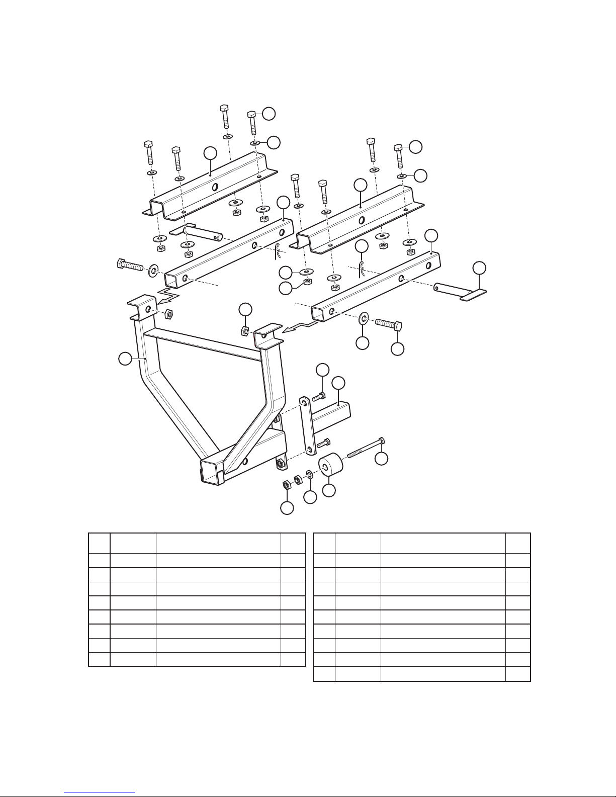
1SM4 Drop Utility Hitch for Fast-Cast 300 and 400 - Illustrated Parts List
15
3
7
6
14
14
10
5
10
5
9
4
2
8
1
11
513
12
17
16
16
Maximum Load Weight
Not to Exceed 240 lbs. Gross
(including the weight of the Spreader)
1
2
3
4
5
6
7
8
1SM3P4
1CS1P11
1CS1P8
1CS1P9
1CS1P41
1SM1P3
1SM1P2
1SM4P10
1/2" Flat Washer
1/2"-13 Lock Nut
3/8"-16 x 1" Hex Bolt
3/8"-16 Lock Nut
3/8" Flat Washer
2-5/16" Hair Pin Clip
5/8" x 5-1/2" Hitch Pin
1/2"-13 x 2" Hex Bolt
Item
No.
2
2
2
8
9
2
2
2
Qty.
Part
No. Description
9
10
11
12
13
14
15
16
17
1CS2P15
1SM4P2
1SM4P3
1SM4P4
1SM4P5
1SM4P9
1SM4P6
1SM4P7
1SM4P8
3/8" Fender Washer
3/8"-16 x 2" Truss Bolt
3/8"-16 Hex Nut
3/8"-16 x 5" Hex Bolt
2" Rubber Stopper
Mounting Rail
Drop Mount Weldment
Mounting Rail Hat Section
Mule Adapter
Item
No.
8
8
2
1
1
2
1
2
1
Qty.
Part
No. Description

15 of 17
Sno-Pro Fast-Cast Series Spreaders
1SM3 3-Point Tractor Mount - Illustrated Parts List
1
2
3
4
5
1SM1P7
1SM1P3
1SM1P2
1SM1P6
1SM1P1
5/16" Linch Pin
2-5/16" Hairpin Clip
5/8" x 5-1/2" Hitch Pin
7/8" x 5-1/2" Lift Arm Pin
3-Point Frame
Item
No.
2
1
1
2
1
Qty.
Part
No. Description
5
3
2
1
4

16 of 17
Sno-Pro Fast-Cast Series Spreaders
1AD1 - Adjustable Deflector (Controls Spread Pattern) 1GC1 - Gate Flow Control Kit for Fast-Cast 2000
1SC3 - Variable Speed Control for Fast-Cast 300 or 400
1SM2 - 2" Light Duty Receiver Mount
(Required for all Fast-Cast 2000 Installations)
1WC3 - Weather Cover for Fast-Cast 300 or 400
ON
POWER SPEED
VARIABLE SPEED CONTROL
3456
7
8
4
4
2
1
GATE POSITION
1
2
3
4
5
Fast-Cast Spreader Optional Accessories

Sno-Pro Fast-Cast Series Spreaders
17 of 17
20
AMP
INPUT OUTPUT
BATTERY
OPTIONAL
CONTROLLER
Move leads to positions
shown when installing
Optional Controller.
SAE 2
COND PLUG
DOUBLE FEMALE 3" JUMPER
(remove jumper for use with
VC-150 Variable Speed Control)
4
6
5
1 2
7
3
8
1
2
3
4
1CS2P27
1CS2P27
1CS2P25
1CS2P29
Wiring Harness for Fast-Cast 300
Wiring Harness for Fast-Cast 400
On / Off Switch
Rubber Switch Boot
Item
No.
1
1
1
1
Qty.
Part
No. Description
5
6
7
8
1CS2P33
1CS9P7
1CS2P34
1SC3
Fuse Holder
20 Amp Mini-Fuse
3/8" Ring Terminal
Optional Variable Speed Controller
Item
No.
1
1
2
1
Qty.
Part
No. Description
Wiring Harness for Fast-Cast 300 and 400 Spreaders - Illustrated Parts List
From all of us at Curtis, Thank You for choosing our products!
Notes:
This manual suits for next models
8
Table of contents
Other Sno-Pro Spreader manuals

Popular Spreader manuals by other brands


Earth Way
Earth Way EV-N-SPRED C22HD Assembly and operating instructions

Earth Way
Earth Way EV-N-SPRED GT 3100 Assembly and operating instructions

Earth Way
Earth Way Ev-N-SprEd 2030 Series Assembly and operating instructions

TMG
TMG TMG-MSS10 product manual

BE Ag & Industrial
BE Ag & Industrial BE-PFS G Series Operations & parts manual

HURST
HURST KL-32 operating instructions


