AIRFLO PSV-8L Programming manual

OPERATORS MANUAL –PSV-8L (ELECTRIC) AIR FLO MANUFACTURING., CO INC.
1 | P a g e
Contents
Pre-Use Checklist .................................................. 1
Vehicle Requirements........................................... 2
Spreader and Material Weights....................... 3
Safety .................................................................... 3
Installation Instructions ........................................ 4
Mounting the Spreader onto the Vehicle........ 4
Things to Know after Mounting the Spreader
................................................................. 5
Mounting the Spinner/Chute Assembly.......... 5
Spreader Maintenance ......................................... 7
Part List ................................................................. 9
Spinner/Chute Assembly ................................. 9
Hopper Assembly ........................................... 14
MATERIAL SPREADER WARRANTY ...................... 15
Pre-Use Checklist
oRead this entire Owner’s Manual
before attempting to operate or
install the spreader.
oTo avoid overloading the sander
check the recommended maximum
payload for the sander before
loading or operating.
oCheck all CAUTION, WARNING and
DANGER decals on the spreader
before operating. Refer to figures 1-
5.
oMake sure the motor cover is
securely fastened to the spreader
before operating.
oVerify that all personnel are clear of
the spreader spray area before
operating
oMake sure that the spreader is
securely fastened to the vehicle.
Figure 1.

OPERATORS MANUAL –PSV-8L (ELECTRIC) AIR FLO MANUFACTURING., CO INC.
2 | P a g e
Figure 2. Figure 4.
Figure 3. Figure 5.
Vehicle Requirements
The spreader must be mounted on a ¾ to a 1 ton pick-up above 8500 # GVWR.
CAUTION
Do not overload the vehicle
beyond its GVWR or GAWR.
Check the vehicle’s load rating
certification sticker for
maximum vehicle capacity.

OPERATORS MANUAL –PSV-8L (ELECTRIC) AIR FLO MANUFACTURING., CO INC.
3 | P a g e
Spreader and Material Weights
Safety
1. Persons who install, mount, operate,
or service this equipment must be
properly instructed and warned.
2. Read operator manuals completely
before operating the equipment.
3. Read all instructional, cautionary,
and warning decals.
4. Check the spreader to ensure that
all shields and gates are in place.
5. Use care when mounting and
dismounting the spreader.
6. Make sure to turn off all power to
the spreader before performing any
repairs, maintenance, or
inspections.
7. Keep all personnel and property
away from the chute/spinner
assembly while the spreader is in
operation.
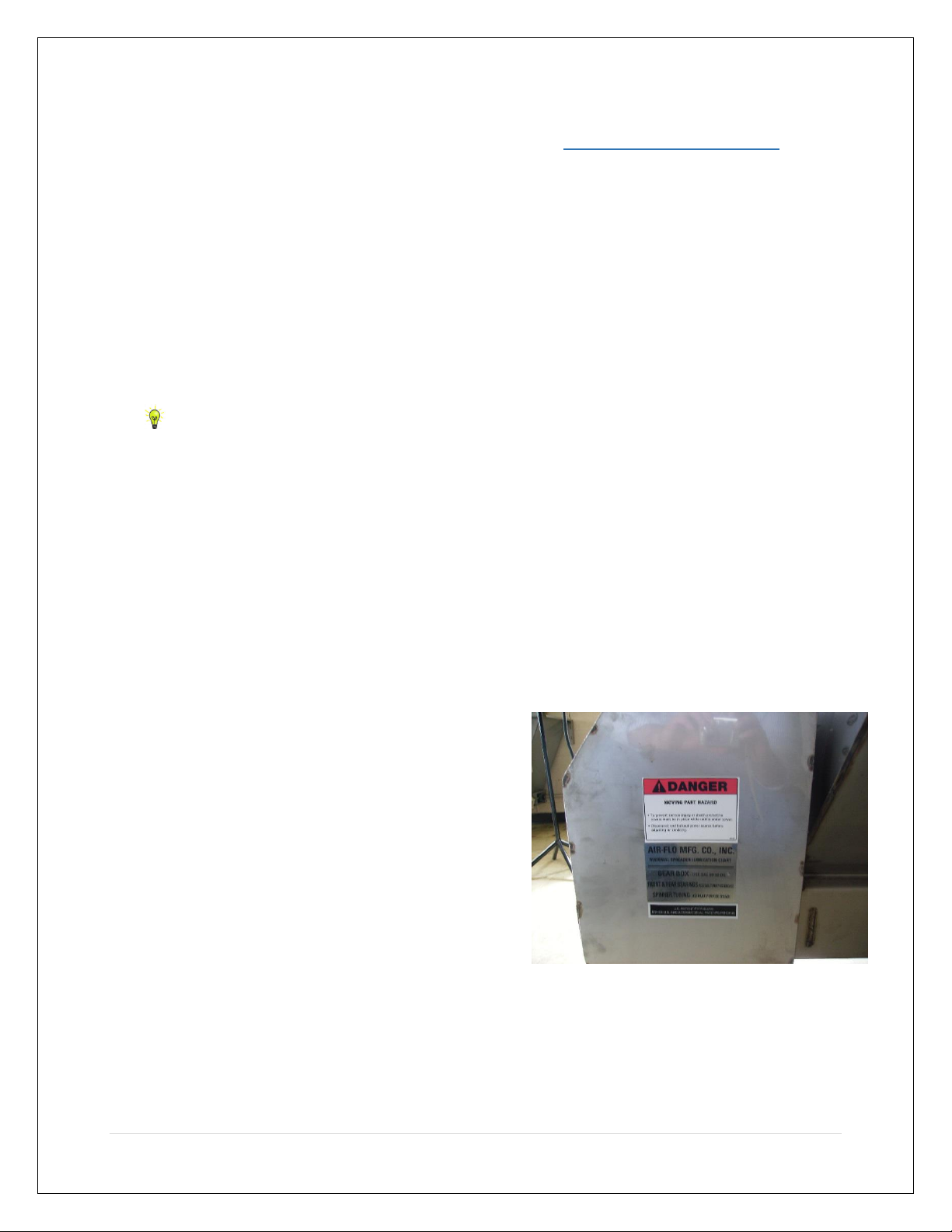
8. Keep the spreader unit and
components in proper working
condition. Replace any missing or
damaged safety signs.
9. Any unauthorized modifications to
the spreader and related
components may impair its
functions and/or safety.
10. Check to make sure all safety guards
are securely mounted into place
before operating the spreader.
11. Keep all loose clothing, hair, jewelry
and limbs clear of the spreader
before starting or operating the
spreader.
12. Do not adjust, clean, oil or unclog
material jams without first turning
off the spreader, removing the
engine spark plug and control panel
fuse.
13. Do not climb on or in the spreader
during operation.
14. Do not ride the spreader while in
operation.
15. Do not attempt to operate the
spreader when it is in need of
maintenance or repair.
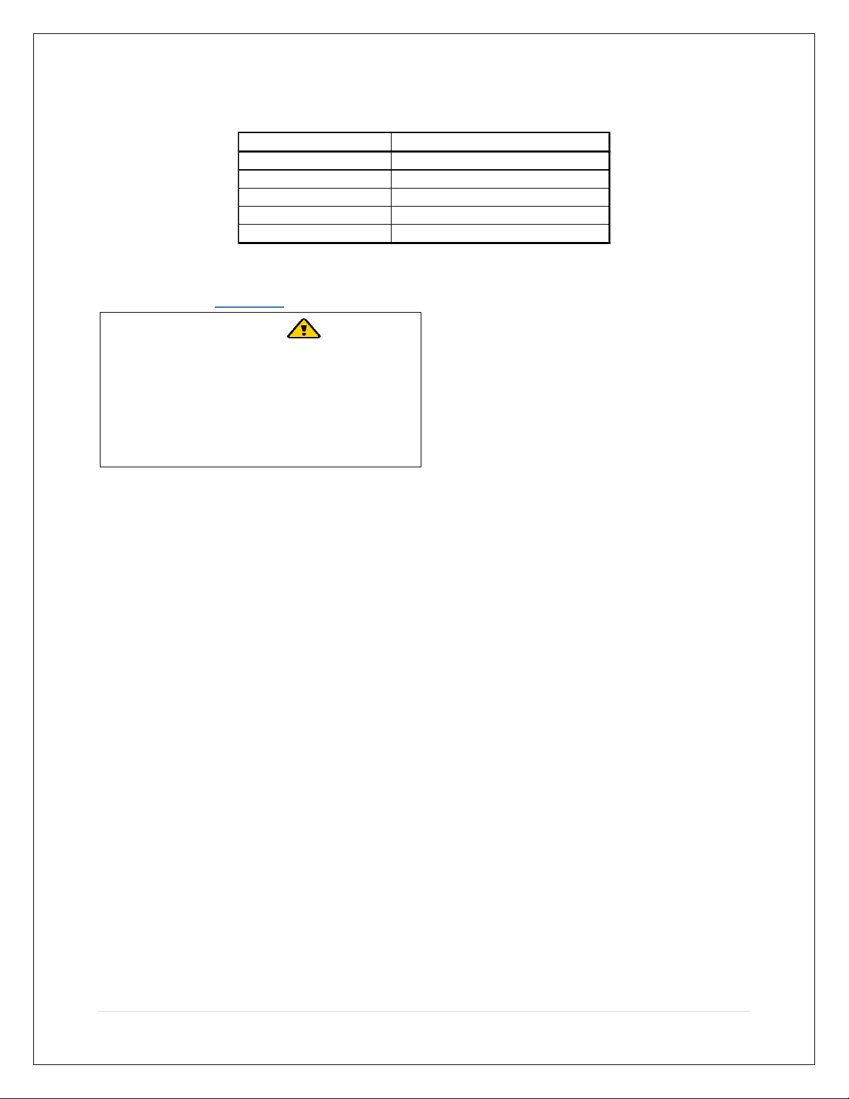
MATERIAL WEIGHT (POUNDS PER CUBIC YARD)
PSV-8E 650 lbs.
#1 Rock Salt 950 lbs.
#2 Rock Salt 1,215 lbs.
Coarse Sand-Dry 2,565 lbs.
Coarse Sand- Wet 3,240 lbs.
WARNING
Observe the following Safety Precautions
before, during and after operating the
spreader. By following these precautions
and common sense, possible injury to
persons and potential damage to this may
be avoided.

OPERATORS MANUAL –PSV-8L (ELECTRIC) AIR FLO MANUFACTURING., CO INC.
4 | P a g e
Installation Instructions
Mounting the Spreader onto the
Vehicle
1. Install the inverted “V” in the
spreader using the 3/8 - 16X 1” hex
bolts, 3/8” nuts, and 3/8” washers
provided.
2. Remove the tailgate from the
vehicle.
3. Lift the spreader by attaching the
lifting device to the slot on the
passenger side of the rear inside
brace.
4. Place the spreader on top of two
pieces of lumber so that the lumber
rests under the side gussets as
shown in figure 7. NOTE: This will
help to remove any excess material
that accumulates under the
spreader.
5. Place the spreader in the back of the
vehicle so that it is centered to the
vehicle and the rails of the spreader
are 14” from the rear of the truck.
6. Bolt the spreader to the vehicle
frame through side gussets and the
lumber.
7. Tie the spreader to the vehicle from
the tie-down eyes to the vehicles
anchor points.
Bill of Materials
Figure 6.
Figure 7.
CAUTION
Check the rated maximum payload of
the lifting device before lifting the
spreader.

OPERATORS MANUAL –PSV-8L (ELECTRIC) AIR FLO MANUFACTURING., CO INC.
5 | P a g e
Things to Know after Mounting the
Spreader
A. The tie-down straps are provided for
the purpose of securing the
spreader to the vehicle only and are
not to be used for any other
purpose. It is imperative that the
spreader be tied to the vehicle at all
times.
B. Be sure to verify with vehicles
manufacturer that the factory
installed anchor points are designed
for this application.
C. Periodically check to see if the
spreader mounting hardware is
securely tightened.
Mounting the Spinner/Chute
Assembly
1. Attach the Spinner/Chute Assembly
to the spreader inserting the lock
pins, shown in Figure 8, into the two
holes located at the end of the rails
of the spreader as shown in Figure 9.
2. Install the roller chain between the
sprocket mounted to the
Spinner/Chute Assembly and the
Motor Sprocket. Make sure both
sprockets are in-line with one
another. Tighten the gearbox
sprocket set screw. Install the roller
chain master link. See Figure 10.
Figure 8.
Figure 9.
Figure 10.

OPERATORS MANUAL –PSV-8L (ELECTRIC) AIR FLO MANUFACTURING., CO INC.
6 | P a g e
3. Adjust the tension of the roller chain
by loosening the Pillow Block
Bearings that are supporting the
Spinner Shaft. Move the shaft either
towards or away from the Motor
Sprocket to adjust the tension. The
correct chain tension should allow a
5/16” deflection in the chain
midway between both chain
sprockets. See Figures 11-12.
NOTE: Be sure to maintain the
vertical alignment between the
Spinner Shaft and the bearings
before re-tightening the hardware.
4. Install the chain guard using the
three ¼-20 X ¾” hex head bolts, lock
washers, and nuts.
5. Torque the 3/8-16 x 1-1/4” Pillow
Block Bolts to 236 Inch-Pounds (20
Foot-Pounds).
NOTE: At this point the spreader control
unit is ready to be installed. For
installation and operation instructions,
please refer to the “Electric Spreader
Control Manual” that has been provided.
Figure 11.
Figure 12.
CAUTION
Do not over-tighten the chain
tension. This can cause damage to
the chain, shaft, bearings and the
Motor.
Pillow Block Bolts

OPERATORS MANUAL –PSV-8L (ELECTRIC) AIR FLO MANUFACTURING., CO INC.
7 | P a g e
Spreader Maintenance
1. Use dielectric grease on all electrical
connections before an electrical
connection is made or after a
connector is disconnected.
2. Grease the following:
a. Idler Shaft Bushings (2)
b. Drive Shaft Bushings (2)
c. Spinner Shaft Bushings (2)
d. Flanged Bearing located
between gearbox and clutch
e. Gearbox Input Shaft Bearing.
NOTE: Do not over grease. Can
cause seal damage.
3. Check the alignment of the
sprockets periodically.
4. Inspect the bearings in the motor
and the pillow blocks for proper
lubrication periodically.
5. Maintain the correct tension on the
following chains using the following
information:
a. Drag Chain Tension-Check to
make sure that the distance
between the end of the rail and
the point of contact between the
chain and the lower flange of the
rail is 26” to 30”. See Figure 13.
Turn the screws shown in
Figures 14 and 15 to adjust the
chain tension as needed.
Figure 13.
Figure 14.
Figure 15.

OPERATORS MANUAL –PSV-8L (ELECTRIC) AIR FLO MANUFACTURING., CO INC.
8 | P a g e
b. Motor to Conveyor Shaft Drive
Chains-Adjust the chain tension for
the sprocket assembly which
transmits power to the conveyor
shaft by loosening the pillow block
bearing bolts and sliding the shaft
and bearings in the desired
direction. Then torque the 3/8-16
Pillow Block Bolts back to 236 Inch-
Pounds (20 Foot-Pounds) when
finished. See Figure 16. NOTE: Be
sure to maintain the horizontal
alignment of the shafts to the
chains. Failure to do so could result
in damage to the sprockets, motor,
shafts, and chains.
Figure 16.
c. Motor to Spinner Shaft Drive
Chain-Correct tension for the
Drive Chain is also a 5/16”
deflection at the mid-point
between the two sprockets.
Adjust the chain by loosening
the Pillow Block Bolts as was
shown in Figures 11 and 12 and
slide the pillow blocks in the
desired direction.
6. Empty the spreader of all snow
control material when not in use to
prevent a frozen feed chain.
7. Wash out the spreader when it is
not in use and at the end of the
season to remove all snow control
materials. Thoroughly dry all metal
surfaces. Paint and oil all bare
carbon steel surfaces to help protect
against rust build-up. Properly store
spreader during the off-seasons.

OPERATORS MANUAL –PSV-8L (ELECTRIC) AIR FLO MANUFACTURING., CO INC.
9 | P a g e
Part List
Spinner/Chute Assembly

OPERATORS MANUAL –PSV-8L (ELECTRIC) AIR FLO MANUFACTURING., CO INC.
10 | P a g e
24. Spinner
Motor Power
Harness
07262
26. Pin
51,143
28. Spring
10,036
27. Roll
Pin
19,029
25. Conveyor
Motor Power
Harness
07261

OPERATORS MANUAL –PSV-8L (ELECTRIC) AIR FLO MANUFACTURING., CO INC.
11 | P a g e
35. Lower Chain
Drive 04017
33. Top Drive
Chain 04015
34. Middle Drive
Chain 04016

OPERATORS MANUAL –PSV-8L (ELECTRIC) AIR FLO MANUFACTURING., CO INC.
12 | P a g e

OPERATORS MANUAL –PSV-8L (ELECTRIC) AIR FLO MANUFACTURING., CO INC.
13 | P a g e
Chute Body with 12 Inch Extension

OPERATORS MANUAL –PSV-8L (ELECTRIC) AIR FLO MANUFACTURING., CO INC.
14 | P a g e
Hopper Assembly

OPERATORS MANUAL –PSV-8L (ELECTRIC) AIR FLO MANUFACTURING., CO INC.
15 | P a g e
MATERIAL SPREADER WARRANTY
AIR-FLO MANUFACTURING CO., INC., hereinafter referred to as “Manufacturer”, warrants each
new material spreader sold by the manufacturer to be free from defects in material and
workmanship, under normal use and service, for a period of One (1) year after the date of
delivery to the original retail purchaser, and Manufacturer will, at its option, replace or repair,
at one of the Manufacturer’s Dealers, or at a point designated by the Manufacturer, any part or
parts which shall appear to the satisfaction of the Manufacturer upon inspection at such point,
to have been defective in material or workmanship. This warranty does not obligate the
Manufacturer to bear any transportation charges in connection with the replacement or repair
of defective parts.
This warranty shall not apply to any spreader which shall have been installed or operated in a
manner not recommended by the Manufacturer; not to any spreader which shall have been
repaired, altered, neglected, or used in any way which, in the Manufacturers opinion, adversely
affects its performance; nor to any spreader in which parts not manufactured by the
Manufacturer, or supplied by the Manufacturer or by one of the Manufacturers distributors or
service centers, have been used; nor any accessories installed on the spreader where the
accessory manufacturer has its own warranty; nor to normal maintenance services or
replacement of normal service items.
Manufacturer reserves the right to modify, alter, and improve any spreader or parts without
obligation to replace any spreader or parts previously sold with such modified, altered, or
improved spreader or part.
THIS WARRANTY, AND THE MANUFACTURER’S OBLIGATION HEREUNDER, IS IN LIEU OF ALL
OTHER WARRANTIES, EXPRESS IMPLIED, OR STATUTORY, INCLUDING ANY WARRANTIES OF
MERCHANTABILITY OR OF FITNESS FOR A PARTICULAR PURPOSE, and all other obligations or
liabilities, including special or consequential damages or contingent liabilities arising out of
failure of any spreader or part to operate properly. No person is authorized to give any other
warranty or to assume any additional obligation on the Manufacturer’s behalf unless made in
writing and signed by the Manufacturer.

OPERATORS MANUAL –PSV-8L (ELECTRIC) AIR FLO MANUFACTURING., CO INC.
16 | P a g e
OPERATORS MANUAL-PSV-8L (ELECTRIC) REVISION
HISTORY
REVISION
LEVEL
REVISION
DATE
PAGES
REVISED
DESCRIPTION OF REVISION
Table of contents
Other AIRFLO Spreader manuals
Popular Spreader manuals by other brands

Ferris
Ferris Rover Series Operator's manual

IMS
IMS Ground Effect Fire Lighter Operation manual

Precision Products
Precision Products SB4300RD Parts list and instructions

Trynex International
Trynex International SnowEx Pro 575X owner's manual

Agri-Spread
Agri-Spread Chain AS55C operating manual

Conestoga
Conestoga CM-25 Operator's manual