Sno-Way 99101220 Operating instructions
97101982A
INSTALLATION &
OWNER’S MANUAL
29VSKD SERIES
SKID STEER SNOW PLOW
99101237 & 99101220
WITH SERIAL NUMBERS AFTER:
29VSKD200000
Sno-Way® Is a registered trademark of Sno-Way International, Inc.
V-Wing™and MaxAdjust™are trademarks of Sno-Way International, Inc.
©2015 Sno-Way®International

1
TABLE OF CONTENTS
Page
INTRODUCTION ......................................................................................................... 2
SAFETY ...................................................................................................................... 3
THEORY OF OPERATION.......................................................................................... 4
General .............................................................................................................. 4
Plow Operational Limits ................................................................................... 4
Skid Steer Power Unit....................................................................................... 4
Skid Steer V-Plow Hydraulic System .............................................................. 4
PLOWING OPERATION.............................................................................................. 5
Before The Season Begins .............................................................................. 5
Transporting Vehicle With Plow Attached ...................................................... 5
Plowing Like A Pro ........................................................................................... 5
Plow Storage ..................................................................................................... 5
TROUBLESHOOTING GUIDE.................................................................................... 6
Introduction ....................................................................................................... 6
Trouble Shooting General Quick Reference................................................... 6
Troubleshooting Chart ...................................................................................... 6
MAINTENANCE .......................................................................................................... 7
General .............................................................................................................. 7
Periodic Inspection........................................................................................... 7
Electrical Quick Disconnect Plugs.................................................................. 7
Hydraulic Cylinders .......................................................................................... 7
Fluid Compatibility ........................................................................................... 7
Special Fasteners Torques and Requirements .............................................. 7
INSTALLATION ........................................................................................................... 8
Control Wiring Installation ............................................................................... 8
Mounting Snow Plow To Vehicle ................................................................... 10
Removing Snow Plow From Vehicle ............................................................. 11
Plow Adjustment............................................................................................. 11
Trip Spring Adjustment .................................................................................. 12
WIRING SCHEMATIC ............................................................................................... 13
HYDRAULIC SCHEMATIC........................................................................................ 14
TORQUE SPECIFICATIONS..................................................................................... 15
DEALER CHECKLISTS............................................................................. Rear Cover
2
This manual was written for the assembly, installation and
maintenance of your new Sno-Way Skid Steer V-Snow
Plow. Most importantly, this manual provides an operating
plan for safe use. Refer to the Table of Contents for an
outline of this manual.
Please keep this manual with your machine at all times as
reference material and so it can be passed on to the next
owner if the machine is sold.
We require that you read and understand the contents of
this manual COMPLETELY, especially the chapter on
SAFETY, before attempting any procedure contained in
this manual.
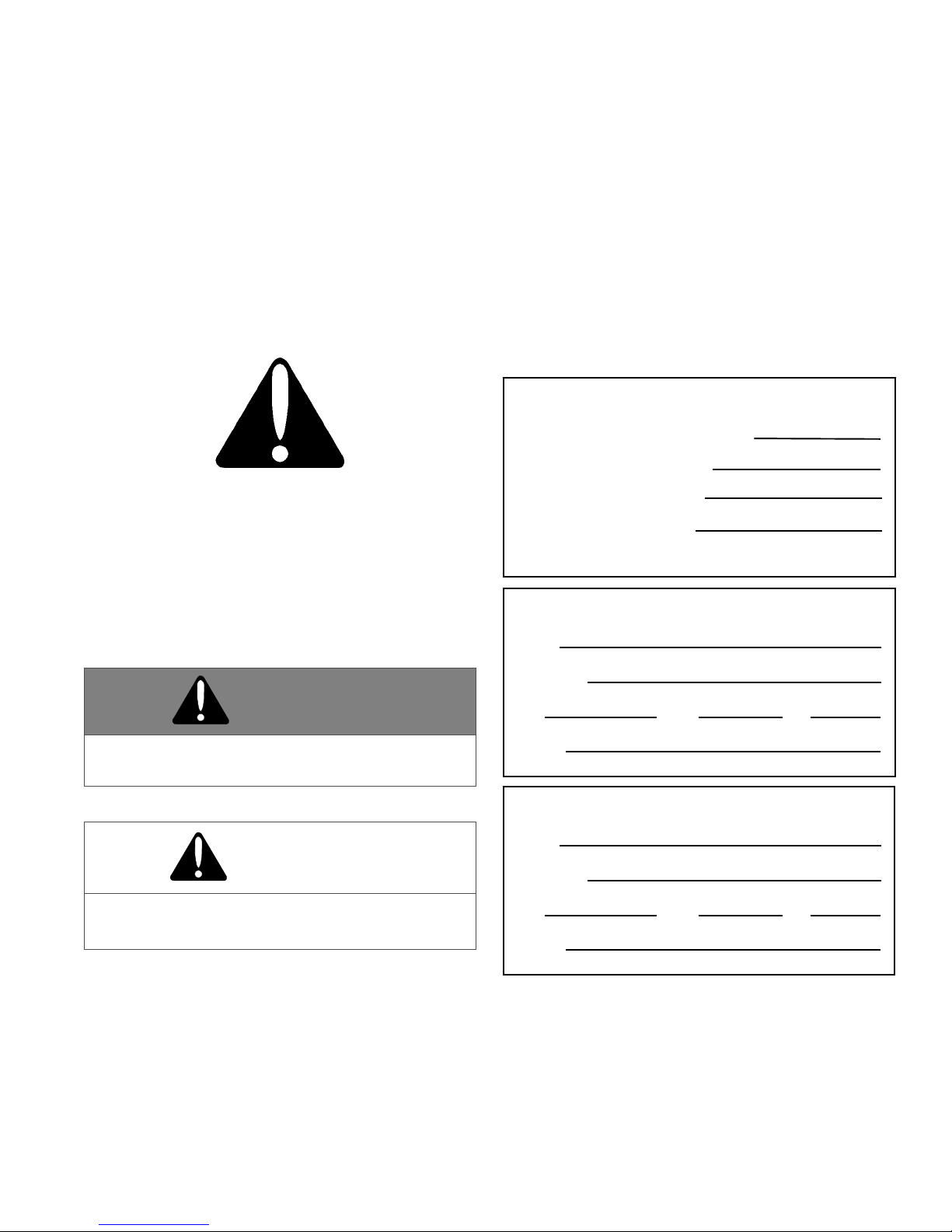
The Society of Automotive Engineers has adopted
this SAFETY ALERT SYMBOL to pinpoint character-
istics that, if NOT carefully followed, can create a
safety hazard. When you see this symbol in this man-
ual or on the machine itself, BE ALERT!, your per-
sonal safety and the safety of others, is involved.
• Defined in the next column, are the SAFETY
ALERT messages and how they will appear in this
manual.
NOTE: Additional information concerning the equipment
or the procedure that may or may not be contained else-
where in this manual.
WARNING
FAILURE TO HEED CAN RESULT IN INJURY OR
DEATH.
CAUTION
Information, that if not carefully followed, can
cause minor injury or damage to equipment!
BE AWARE! It is illegal to remove, deface or other-
wise alter the safety decals mounted on this equip-
ment.
Record the Skid Steer V-Plow Serial Number, Blade
Model Number and Blade Serial Numbers in the space
provided below as a handy record for quick reference.
The Skid Steer V-Plow Serial Number is located on the
main frame. The Blade Serial Numbers are located on
one of the middle ribs of each wing. The Blade Model
Number should be recorded from your sales invoice.
These plates contain information that your Dealer needs
to answer questions or to order replacement parts, if
needed, for your unit.
We reserve the right to make changes or improve the
design or construction of any part(s) without incurring the
obligation to install such parts or make any changes on
any unit previously delivered.
INTRODUCTION
DEALER
NAME
PHONE ( ) –
ADDRESS
CITY STATE ZIP
(FILL IN)
NAME PLATE DATA
LEFT WING SERIAL NUMBER
(FILL IN)
BLADE MODEL NUMBER
(Located on Blade Frame)
ORIGINAL PURCHASER
NAME
PHONE ( ) –
ADDRESS
CITY STATE ZIP
(FILL IN)
RIGHT WING SERIAL NUMBER
(Located on Blade Frame)
SKID STEER V-PLOW SERIAL NUMBER
(Back of A-Frame)

3
BEFORE ATTEMPTING ANY PROCEDURE IN THIS
BOOK, READ AND UNDERSTAND ALL THE SAFETY
INFORMATION CONTAINED IN THIS SECTION. IN
ADDITION, ENSURE ALL INDIVIDUALS WORKING
WITH YOU ARE ALSO FAMILIAR WITH THESE
SAFETY PRECAUTIONS.
For your safety Warning and Information Decals have
been placed on this product to remind the operator
to take safety precautions. It is important that these
decals are in place and are legible before operation
begins. New decals can be obtained from Sno-Way or
your local dealer.
REMEMBER The careful operator is the best
operator. Most accidents are caused by human error.
Certain precautions must be observed to prevent the
possibility of injury to operator or bystanders and/or
damage to equipment.
NEVER operate Plow when under the influence of
alcohol, drugs or other medications that could hamper
your judgement and reactions. An accident may result in
serious injury or death to other persons or yourself.
ALWAYS operate vehicle in a well-ventilated area. The
carbon monoxide in exhaust gas is highly toxic and can
cause serious injury or death.
NEVER allow hands, hair or clothing to get near any
moving parts such as fan blades, belts and pulleys. Never
wear neckties or loose clothing when working on the
vehicle.
NEVER wear wrist watches, rings or other jewelry when
working on the vehicle or individual equipment. These
things can catch on moving parts or cause an electrical
short circuit that could result in serious personal injury.
ALWAYS wear safety goggles when working on the
vehicle to protect your eyes from battery acid, gasoline,
and dust or dirt from flying off of moving engine parts.
ALWAYS be aware of and avoid contact with hot
surfaces such as engine, radiator, and hoses.
ALWAYS wear safety glasses with side shields when
striking metal against metal! In addition, it is
recommended that a softer (non-chipable) metal material
be used to cushion the blow. Failure to heed could result
in serious injury to the eye(s) or other parts of the body.
NEVER allow children or unauthorized person to
operate this unit.
NEVER exceed 45 m.p.h. when snow plow is attached
to vehicle. Braking distances may be increased and
handling characteristics may be impaired at speeds
above 45 m.p.h.
ALWAYS lock the vehicle when unattended to prevent
unauthorized operation of the plow.
ALWAYS check the job site for terrain hazards,
obstructions and people.
NEVER exceed 10 m.p.h. when plowing. Excessive
speed may cause serious injury and damage of
equipment and property if an unseen obstacle is
encountered while plowing.
ALWAYS position blade so it does not block path of
headlamps beam. Do not change blade positions while
traveling. An incorrect plow position blocking headlamp
beam may result in an accident.
ALWAYS check surrounding area for hazardous
obstacles before operating this unit.
ALWAYS inspect the unit periodically for defects. Parts
that are broken, missing or plainly worn must be replaced
immediately. The unit, or any part of it should not be
altered without prior written approval of the manufacturer.
ALWAYS shut off the vehicle engine, place the
transmission in Neutral or Park, turn the ignition switch to
the “OFF” position and firmly apply the parking brake of
the vehicle before attaching or detaching the blade from
the vehicle or when making adjustments to the blade.
ALWAYS inspect lift system bolts and pins whenever
attaching or detaching the plow, and before traveling.
Worn or damaged components could result in the plow
dropping to the pavement while driving, causing an
accident.
ALWAYS keep hands and feet clear of blade and A-
Frame when attaching or detaching plow.
NEVER stand between the vehicle and blade or directly
in front of blade when it is being raised, lowered or
angled. Clearance between vehicle and blade decreases
as blade is operated and serious injury or death can
result from blade striking a body or dropping on hands or
feet.
NEVER work on the vehicle without having a fully
serviced fire extinguisher available. A 5 lb or larger CO2
or dry chemical unit specified for gasoline, chemical or
electrical fires, is recommended.
NEVER smoke while working on the vehicle. Gasoline
and battery acid vapors are extremely flammable and
explosive.
NEVER use your hands to search for hydraulic fluid
leaks; escaping fluid under pressure can be invisible and
can penetrate the skin and cause a serious injury! If any
fluid is injected into the skin, see a doctor at once!
Injected fluid MUST BE surgically removed by a doctor
familiar with this type of injury or gangrene may result.
REMEMBER it is the owner’s responsibility for
communicating information on the safe use and
proper maintenance of this machine.
SAFETY

4
General
The Sno-Way Skid Loader V-Plow is mounted using a
universal mounting plate. The V-Plow pressure and return
lines are connected to the auxiliary hydraulic quick
couplers. Blade extend and retract functions are operated
by using the skid loader auxiliary hydraulics. Reversing
the flow changes the wing directions. The rocker switch
controls which blade is functioned.
Plow Operational Limits
Figure 1-1
The Sno-Way Skid Steer Plows are designed to plow
snow within certain operational limits. A floating link
enables the plow to "float" over the contours of an uneven
grade during operation. Plowing with all four skid steer
wheels "on the ground" is recommended for optimum
plowing performance and reduced loading on plow
components.
Skid Steer Power Unit
Features
18-30 gpm (gallons per minute)
3000 psi max. operating pressure
3000 psi relief
Auxiliary hydraulic lines
The skid steer is the primary hydraulic source to the V-
Plow. A typical system operates at a maximum pressure
of 3000 psi and maximum flow rate of 30 gpm. The
hydraulic system has a 3000 psi relief that dumps all
excess hydraulic fluid to the tank when the system is
loaded beyond 3000 psi. The auxiliary hydraulic circuit
consists of two lines that come directly from the skid steer
hydraulic pump and are actuated by an auxiliary control in
the cab. The lines are connected to the V-Plow valve
block assembly so that one line feeds pressure and the
other dumps to the tank.
Skid Steer V-Plow Hydraulic System
The auxiliary hydraulics are routed to the valve block
where the hydraulic fluid is diverted for wing functions. To
activate the wing function, diverter valves are actuated for
right wing functions and deactivated for left wing
functions. To change the direction of the wing motion, the
direction of the auxiliary hydraulics is reversed.
Hydraulic Valve Block Assembly
The Hydraulic Valve Block Assembly consists of a valve
body containing two (2) flow control valves and two (2)
check valves.
The valve body directs hydraulic fluid to operate two (2)
hydraulic circuits; angle left side and angle right side. The
angle circuits receive fluid under pressure.
IMPORTANT: The electric coils, which operate the
solenoid valves, require a minimum of 9-1/2 volts DC
for proper operation. Lower voltage will cause erratic
operation, or failure to operate.
Wing Angling Mode Of Operation
Each wing can be angled forward or rearward
independently by operating the wing angle switch for
either the right or the left wing. Operating the wing angle
switch energizes the solenoid valve. Depending on the
auxiliary hydraulics flow direction, this directs hydraulic
fluid, under pressure, to either the base end (extend) or
rod end (retract) of the wing cylinder, which then moves
the wing forward or rearward.
Controls
Left Wing Angle Switch:
Used to angle the left wing forward and rearward.
Right Wing Angle Switch:
Used to angle the right wing forward and rearward.
FLOATING LINK
THEORY OF OPERATION
5
Before The Season Begins
1. Inspect vehicle safety equipment for proper
operation; brakes, headlights, plowing lights, windshield
wipers, flashers, etc.
2. Inspect the plow, plow frame and all attaching
hardware for wear and corrosion. Replace worn or
damaged parts and clean and repaint exposed metal
parts with a high quality, corrosion resistant enamel.
3. Inspect all fasteners to insure that they are properly
tightened. If any fasteners are loose, re-tighten to the
proper torque (refer to the Torque Specification Chart in
this manual) and carefully inspect the adjacent area for
damage or wear as well as carefully inspecting all
adjacent fasteners for proper torque.
4. Apply a small amount of light oil to the hitch pins and
pivots, to pivot pins between the A-frame and center
tower assembly, between wing cylinder pivot pins and the
lift linkage.
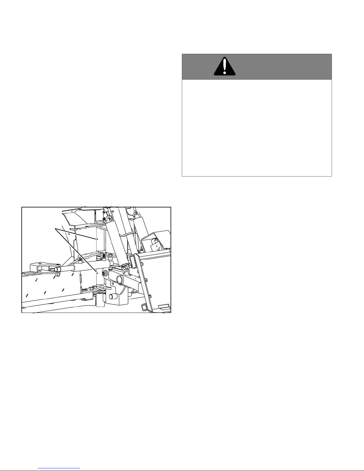
5. Apply oil or grease to the wing pivot pin through two
lubrication holes provided in the pin housing. (See Figure
1-2)
Figure 1-2
6. Check the reservoir oil level (see maintenance
instructions) and repair any oil leaks and worn hoses.
7. Install auxiliary and flashing lights (if not equipped).
Transporting Vehicle With Plow Attached
1. Position the blade out of the beam path of the vehicle
work lights before operating.
2. Inspect plow and plow attaching hardware for wear or
damage before transporting and beginning plow
operations.
Plowing Like A Pro
1. Become familiar with the area to be plowed and mark
potential hazards before the snow falls. Many immovable
objects cannot be seen when covered with snow.
Developing a plan early can save valuable time and
equipment damage. Allow sufficient room to pile snow,
out of the traffic area, with enough space for snow when
the next storm comes.
2. Plow with the storm. The “Pros” are out early
removing only several inches of snow at a time. Allowing
snow to accumulate to unmanageable levels can cause
difficult removal problems and can be costly in terms of
“wear and tear” on equipment. The plow is not a “Ram or
Bulldozer”. If used properly, it will give you many years of
safe and reliable service.
3. Research municipal ordinances for restrictions on the
disposal of snow. Many municipalities do not allow snow
to be placed in roads or throughways.
Plow Storage
1. To avoid corrosion during storage, coat the exposed
(chrome) portion of the wing cylinders with a light grease.
2. Lubricate all pivot points.
3. Make sure that protective caps are on all electrical
connections. A small amount of dielectric grease may be
used to insure a moisture proof seal on the caps.
4. Check and replace any worn and/or damaged
component, such as wearstrips, shoes or deflectors.
Performing preventative maintenance tasks in the spring
when the plow is stored will ensure that you will be ready
to plow in the fall.
WING PIVOT
LUBRICATION
POINTS
WARNING
• Never exceed 10 mph when plowing! Serious
personal injury can result, as well as damage to
equipment and property, if an unseen
obstruction is encountered while plowing.
• Wear your seat belt! Contact with a hidden
obstruction can cause serious personal injury
from bodily contact within the vehicle cab or
whiplash from sudden stops.
FAILURE TO HEED CAN RESULT IN INJURY OR
DEATH.
PLOWING OPERATION

6
TROUBLESHOOTING GUIDE
Introduction
Whenever service is necessary, your local Sno-Way
Dealer knows your plow best and is interested in your
complete satisfaction. Return your V-Plow to your local
Dealer for maintenance service or any other assistance
you may require. If you are unable to do so, this
Troubleshooting Guide should help you determine the
problem. Before attempting the servicing of your plow,
you should possess good mechanical abilities and a total
understanding of the mechanism.
PLEASE: Before calling parts and service personnel be
certain that:
1. You have read this manual carefully and are certain
that all of the suggestions pertaining to your problem
have been attempted.
2. You should have the following information available.
A. Date Snow Plow was originally installed.
B. Main Frame Serial Number.
C. Blade Model Number.
D. Blade Serial Number.
This information should be recorded on page 2 of this
Manual.
General Quick Reference
1. Check oil level in hydraulic system reservoir.
2. Check for external leakage at cylinders, hoses and
power unit.
CAUTION
First read all warning instruction, the safety
messages, and directions before attempting any
adjustments or repairs to your unit!
TROUBLESHOOTING CHART
NOTE: Make sure all electrical connections are correct, that wires are not frayed or corroded before consulting the
following chart:
PROBLEM PROBABLE CAUSE
Left wing extends and retracts, Right
wing does not move as intended.
The valve S1 is stuck open
Check switch for electrical shorts. Switch may be stuck “On” for the S1 valve
Right wing extends and retracts, Left
wing does not move as intended
The valve S2 is stuck shut
Check switch for electrical shorts. Switch may be stuck “On” for the S2 valve
Wings do not move Both coils are "ON" (or both valves are internally stuck shut)
Both wings extend together, but
individual left and right functions
are not possible
No power going to the valves.
• The electrical connection to the remote switch is not connected
• The valves coils have become disconnected
Both wings retract together, but
individual left and right functions
are not possibleonly
No power going to the valves
•The electrical connection to the remote switch is not connected
•The valves coils have become disconnected
Retract rate is slower than extend
rate
Flow to block is not very high: Increase the engine speed
Wings will not retract - Extend only,
but not retract
One of the auxilliarly power lines is disconnected
Wings will not collaspe when hitting
an object
Case drain line disconnected
When wings hits an object the other
wing extends
Case drain line disconnected
FOR ANY OTHER ISSUE, CHECK WITH YOUR SNO-WAY DEALER

7
MAINTENANCE
General
• Before operating, perform a thorough visual
inspection of the equipment. Look for fluid leaks,
cracked, bent or broken components, loose nuts,
bolts or attachments and proper fluid levels.
• A clean hydraulic system is essential to long
pump life and proper performance.
• When adding oil to the reservoir, wipe the area
around the filler port clean before removing the
breather cap. Use clean oil and a clean funnel,
(DO NOT use a cloth or rag to strain the oil).
• The operational environment for snow plows is an
extremely harsh and corrosive one.
• Ensure all electrical connections are clean and
tight.
• To prevent rust from forming, clean and repaint
exposed metal surfaces.
• NEVER operate the equipment with the
protective covers or guards removed.
Periodic Inspection
After approximately every 20 hours of operation perform
the following inspections procedures:
1. Inspect the plow assembly for any damage or
excessive wear. Also inspect all fasteners to insure that
they are properly tightened. If any fasteners are loose re-
tighten to the proper torque (Refer to the Torque
Specification Chart in this manual). Also carefully inspect
adjacent area for damage or wear as well as carefully
inspecting all adjacent fasteners for proper torque.
2. Apply a small amount of light oil to the hitch pins and
pivots, between wing cylinder pivot pins and the lift
linkage.
Electrical Quick Disconnect Plugs
Install protective caps on quick disconnect ends to
prevent corrosion from forming on terminal ends during
storage or when Plow is disconnected from vehicle.
Hydraulic Cylinders
To avoid corrosion during storage, coat the exposed
(chrome) portion of the Angle Cylinders with a light
grease.
Fluid Compatibility
Hydraulic fluid used in skid steers is compatible with the
plow system.
Special Fasteners Torques and
Requirements
IMPORTANT: Incorrectly securing fasteners may
result in incorrect operation, excessive wear, and
early failure of Plow components. It may also void
your warranty.
• ALWAYS check to make sure you are using the
correct torque specification for the fastener you
are using.
• DO NOT use any lubricants on the threads of any
fastener unless specifically called for in the
assembly or maintenance story for that
component.
• NEVER use liquid locking materials, such as
Locktite™ or Threadmaker™, on any fasteners
unless specifically called for in an assembly or
maintenance story for that component.
Standard Fasteners:
The Torque Specifications Chart on page 15 of this
manual should be used as the guide for fastener torque
requirements for most standard fasteners used on the
plow.
Standard fasteners with special torque requirements will
be noted in assembly or service stories pertaining to the
specific piece of equipment.
Hydraulic Fittings:
Hydraulic fittings with lock nuts should be assembled with
at least three full turns of the fitting in the port and then the
lock nut should be tightened to 27 lb.-ft.
8
Control Wiring Installation
1. Position the control box in cab. Secure the control box
using hook and loop fastener provided.
2. Route the power harness lead to the battery (See
Figure 1-4). Connect the YELLOW wire to the negative (-
) battery terminal and the WHITE wire to the positive (+)
battery terminal.
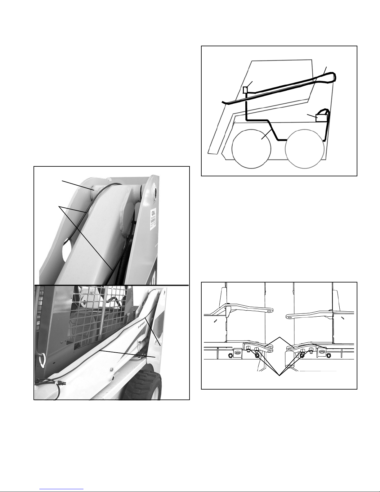
3. Route the control harness lead around the pivot point
on the loader arms on the back of the Skid Steer and
down the top of the loader arms to the front. Allow
enough slack when routing wire so that wiring is not put
in tension when the loader arms are moved. Position the
wiring to prevent pinching when loader arms pivot, and
secure with cable ties. (See Figure 1-3) and (See Figure
1-4).
Figure 1-3
Figure 1-4
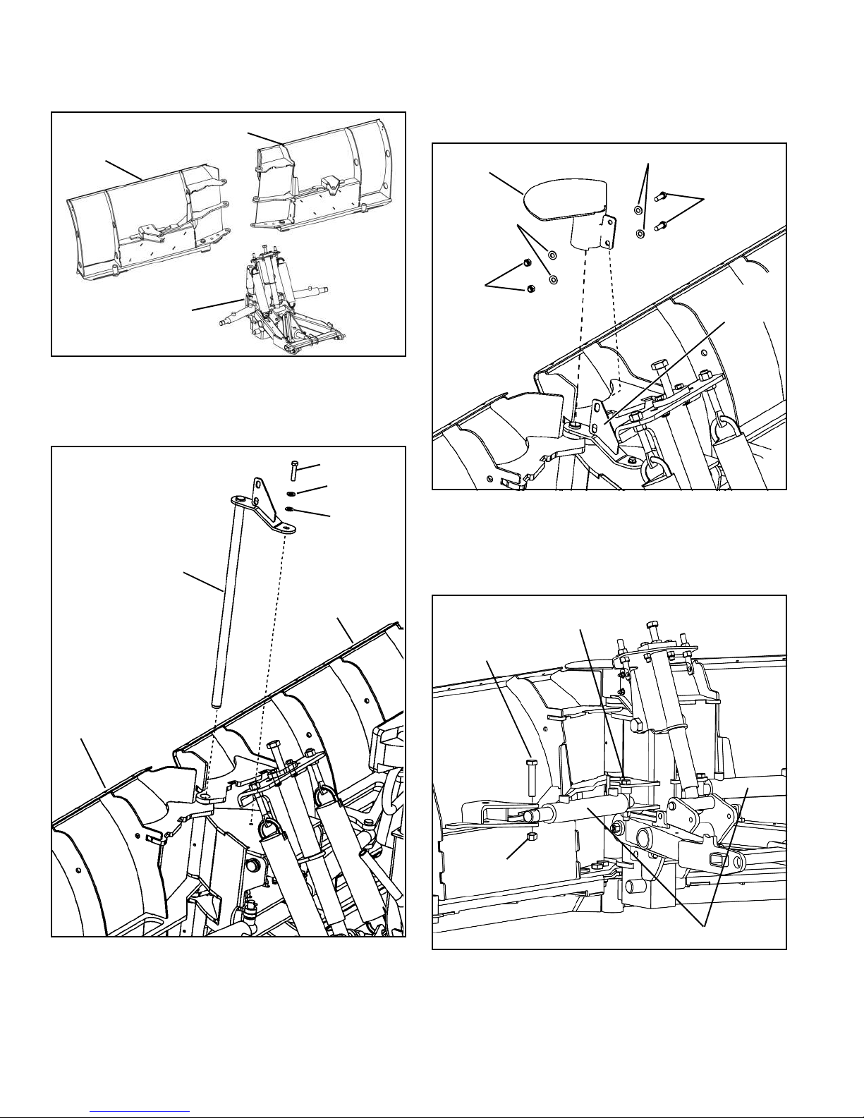
Mechanical Installation
Final Installation
1. Remove the A-frame/tower assembly from the box.
2. Remove power unit.
3. To aid in the pin installation as the blades are
installed, loosen two nuts securing each lower support
plate to the DS and PS wings. (See Figure 1-5)
Figure 1-5
LOADER ARM
PIVOT
CONTROL
HARNESS
LEAD
CONTROL
HARNESS
LEAD
CONTROL
HARNESS
CONTROL
BOX
BATTERY
POWER
HARNESS
LOWER
PLATES
SUPPORT
PLATE NUTS
SUPPORT
INSTALLATION
9
4. Position the drivers side (DS) and passenger side
(PS) wings in front of the A-frame/tower assembly. (See
Figure 1-6)
Figure 1-6
5. Coat main wing pivot pin with grease and insert
completely through the tower, blade section pin holes,
and support plate holes. (See Figure 1-7)
Figure 1-7
6. Secure the main wing pivot pin to the tower assembly
with one 5/16-18 x 1’’ hex head cap screw (p/n
98009149), 5/16" split lock washer (p/n 98009025) and 5/
16 " flat washer (p/n 98009024).
7. After installation of the pin, tighten nuts on the lower
hinge support plates securely if loosened earlier.
8. Install the center shield on the clevis pin retainer
bracket, and secure with two 5/16-18 x 1’’ hex head cap
screws (p/n 98009149), four 5/16" flat washers (p/n
98009024) and two 5/16" lock nuts (p/n 98009150). (See
Figure 1-8)
Figure 1-8
9. Attach angle cylinder base to tower with a 3/4" x 4-1/
2" capscrew and 3/4" locknut. Attach angle cylinder rod to
blade with a 3/4" x 4" capscrew and 3/4" locknut. (See
Figure 1-9) Repeat for opposite angle cylinder.
Figure 1-9
DS WING
A-FRAME/
TOWER
ASSEMBLY
PS WING
CAP SCREW
MAIN WING
LEFT BLADE
RIGHT BLADE
FLAT
SPLIT
PIVOT PIN
WASHER
WASHER
CENTER
SHIELD
NUTS
CAPSCREWS
WASHERS
WASHERS
CLEVIS PIN
RETAINER
BRACKET
CAPSCREW
ANGLE CYLINDERS
3/4" LOCKNUT
3/4"-10 X 4-1/2"
CAPSCREW
3/4"-10 X 4"

10
10. Attach a plow marker to each wing as shown and
secure using 5/16" x 1" cap screws and locknuts. (See
Figure 1-10)
Figure 1-10
11. Loosely connect hydraulic hoses to the wing
cylinders. (See Figure 1-11).
Figure 1-11
12. Loosely position hydraulic hoses in hose clamps (A -
5/16" X 2" self-tapping screw, B - plate, C - clamp blocks)
on each side of the A-frame.
13. Adjust each hose length from clamps to hose end
fittings to 33 in. and tighten both clamp screws. (See
Figure 1-12)
NOTE: If installing screw with an impact wrench, ensure
that the wrench in adjusted to its lowest torque setting to
avoid fastener damage.
Figure 1-12
14. Tighten all hydraulic hose fittings securely.
Mounting Snow Plow To Vehicle
1. Drive up to the snow plow and tilt the universal mount
slightly forward.
2. Hook the top of the universal mount under the lip on
the skid steer adapter plate of the snow plow.
3. Position the snow plow so that it rests flush against
the universal mount and lock the snow plow in place.
4. Connect the hydraulic hoses (V1, V2 and CD) to the
auxiliary hydraulic connectors on the vehicle. Refer to
figure below and the hydraulic schematic on page 14.
Figure 1-13
5. Connect the electrical connector to the vehicle.
5/16" x 1"
CAP SCREWS
PLOW
MARKER
A
B
C
D1
R1
R2
D2
33"
11
Removing Snow Plow From Vehicle
1. Lower the snow plow to the ground.
2. Disconnect the hydraulic hoses and electric
connector from the vehicle.
3. Unlock the universal mount from the snow plow and
slowly back the vehicle away, while tilting the universal
mount slightly forward.
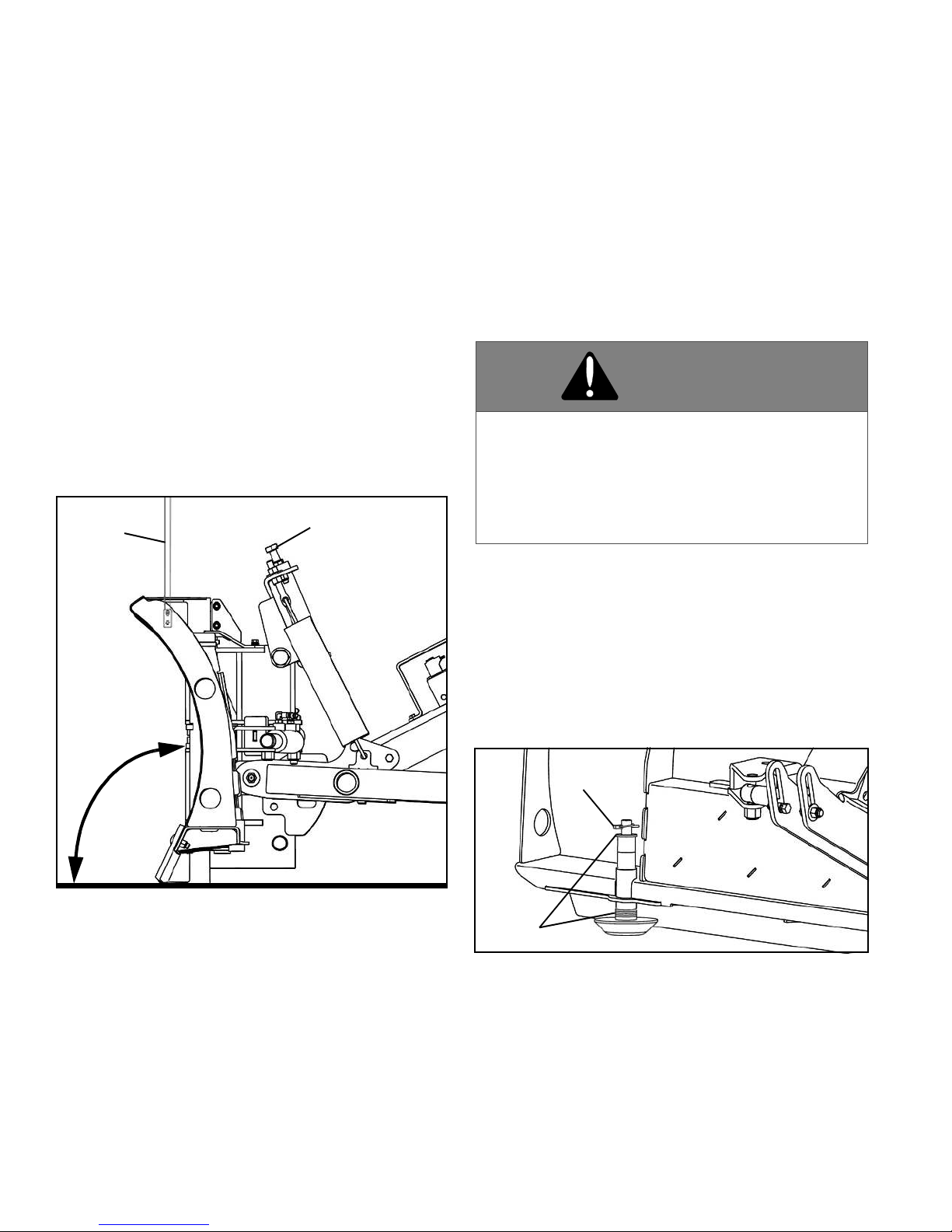
Plow Adjustment
1. The plow frame height should be adjusted relative to
the optimum resting position of the loader arms. To
adjust, remove the locknuts and hex head cap screws
that secure the rear of the A-frame to the mounting lugs
of the universal adapter. Move the A-frame to a higher or
lower position as required and re-install the capscrews
and locknuts. Tighten securely.
2. This plow is equipped with the MaxAdjustTM System
(Patent pending). Adjust capscrew as required to position
center of moldboard at a 90° angle to the ground. (See
Figure 1-14).
Figure 1-14
3. This plow as an option has 4 shoes that may be
installed to help with gravel plowing and aid in over all
cutting edge wear. Two plow shoes are located at the
outboard end of each wing. The two inner plow shoes are
located inboard on the wing underneath the cylinder
mounting area.
IMPORTANT: To ensure the best function of this
Snow Plow, it is a requirement that all four plow
shoes be adjusted equally.
Adjust the plow shoes as follows:
a. Park the vehicle on a smooth level surface. Adjust
the wings straight out on each side and lower the
plow to the ground.
b. When properly adjusted, the plow shoes and
wearstrips contact the ground at the same time.
Determine whether the plow shoes or wearstrips
are off the ground.
• If the plow shoe(s) were off the ground - washers
must be moved from the top to the bottom of the
shoe stem.
• If the wearstrips are off the ground - washers
must be moved from the bottom to the top of the
shoe stem.
c. Raise the plow and place suitable blocking under
the plow to allow at least six inches (6") of
clearance from the bottom of the plow shoes to the
ground.
d. Lower plow onto blocking. Turn ignition switch OFF
and apply the emergency brake.
e. Adjust shoe assemblies by removing shoe mounting
lynch pin and adding or subtracting washers on the
top or bottom of the shoe mounting location. (See
Figure 1-15).
Figure 1-15
PLOW TILT ADJUSTMENT
CAP SCREW
90°
MARKER
WARNING
Keep hands and feet clear of wings and center
section when setting blocking and lowering
plow. Moving or falling assemblies could result
in serious injury.
FAILURE TO HEED CAN RESULT IN INJURY
OR DEATH.
WASHERS
PIN
12
f. After the disk shoe position is properly adjusted
place washers on the shoe stem - above the plow
frame and below the retaining lynch pin - to remove
all up and down movement of the disk shoe in the
frame. Failure to do so will result in excessive wear
of the holes in the frame or bending of the shoe
stem.
IMPORTANT: Snap lynch pin ring over so that it
contacts the pin. If ring does not contact lynch pin,
rotate the pin and reverse the direction of the ring. If
the ring does not contact the pin it is not locked and
could fall out.
g. Lower the plow to the ground and check adjustment.
Repeat adjustment if required.
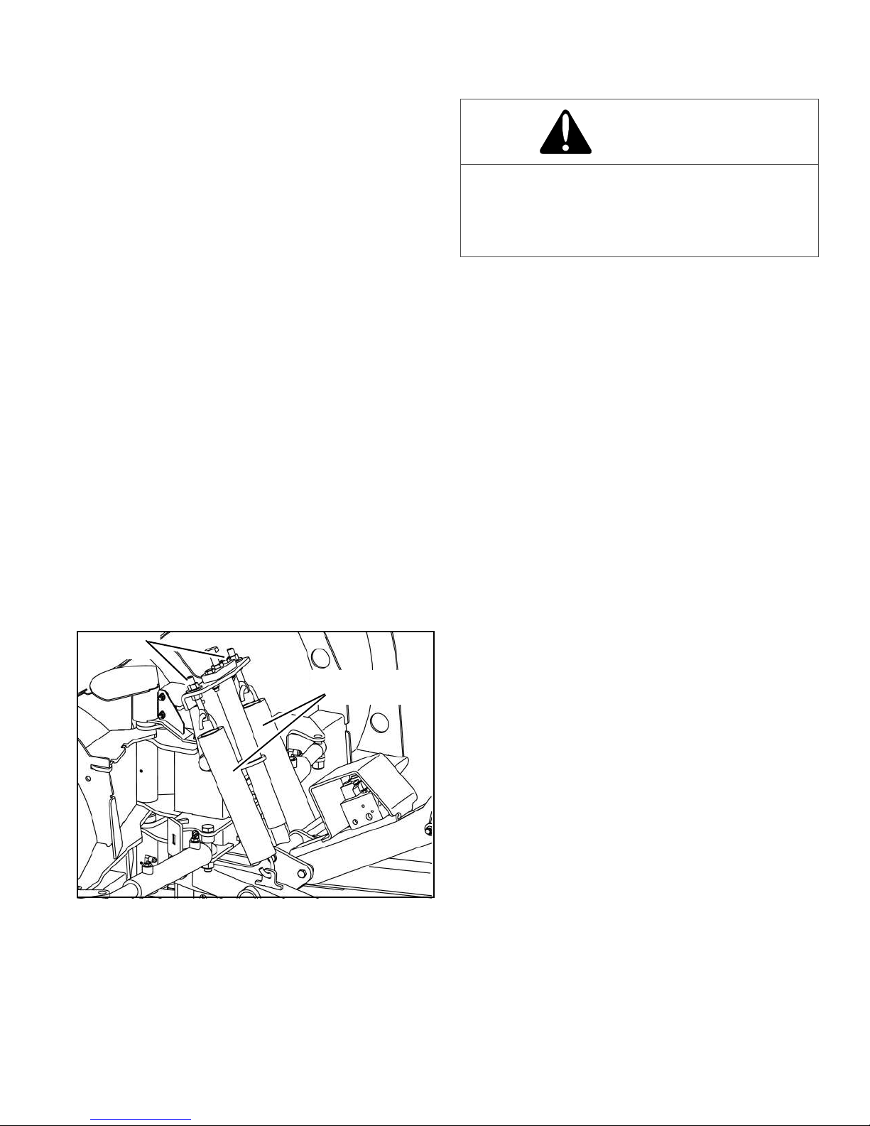
Trip Spring Adjustment
NOTE: The trip springs are factory installed and
adjusted, but adjustment should be checked during plow
set-up and installation.
Springs are properly adjusted when two or more coils
allow a 0.010" feeler gauge to just pass between the
separated coils. (A 3 x 5" post card is approximately the
same thickness.)
If re-adjustment is required:
1. Raise the plow to the full UP position and support the
blade with suitable blocking.
2. Turn the vehicle OFF, apply the parking brake and
remove the ignition key.
3. Check to make sure that the springs are installed as
illustrated. (See Figure 1-16).
Figure 1-16
4. Loosen the lower jam nut on each eyebolt. (See
Figure 1-16).
5. Tighten the upper retaining nut until a 0.010" feeler
gauge can pass between two or more coils on each
spring.
6. Hold the upper nut and tighten the lower nut securely
on each spring.
NUTS
0.015 (1/64") GA
P
MAXIMUM
CAUTION
• Do not overtighten springs. If more than 0.015"
(1/64") gap appears between coil with Plow at
rest, damage could occur to equipment during
plowing.

13
WIRING SCHEMATIC
14
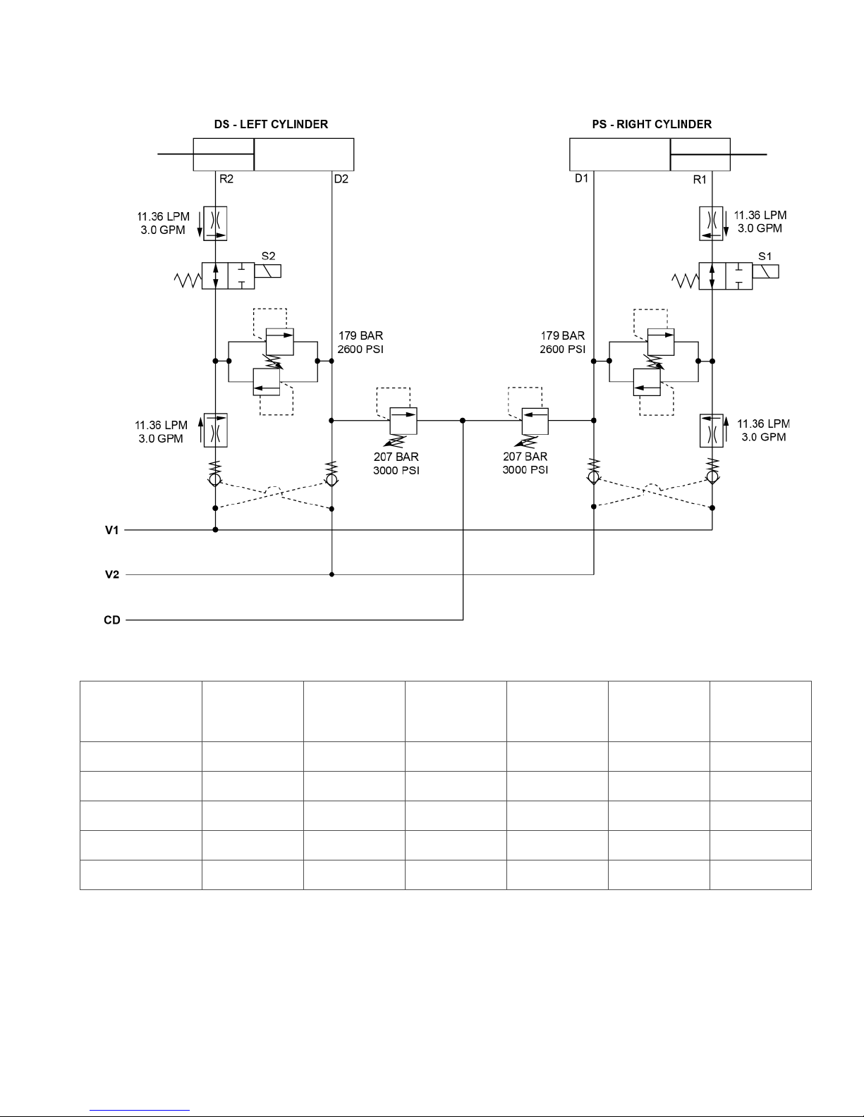
HYDRAULIC SCHEMATIC
PLOW
FUNCTION
SWITCH
POSITION
CYLINDER
PRESSURIZED
PORT
S1
SOLENOID
STATUS
S2
SOLENOID
STATUS
FLOW
INLET
FLOW
TO TANK
NEUTRAL MIDDLE - OFF N/A OFF OFF V1 V2
LEFT EXTEND LEFT D2 ON OFF V2 V1
LEFT RETRACT LEFT R2 ON OFF V1 V2
RIGHT EXTEND RIGHT D1 OFF ON V2 V1
RIGHT RETRACT RIGHT R1 OFF ON V1 V2

15
TORQUE SPECIFICATIONS
DO NOT use these values if a different torque value or tightening procedure is given for a specific application.
Fasteners should be replaced with the same or higher grade. If higher grade fasteners are used, these should only be
tightened to the strength of the original.
a“Lubricated” means coated with a lubricant such as engine oil, or fasteners with phosphate and oil coatings.
b“Dry” means plain or zinc plated without any lubrication
* Values with asterisk are in lb-in.
Grade 1 Grade 2 Grade 5, 5.1 or 5.2 Grade 8 or 8.2
LubricatedaDrybLubricatedaDrybLubricatedaDrybLubricatedaDryb
SIZE lb-ft lb-ft lb-ft lb-ft lb-ft lb-ft lb-ft lb-ft
8-32 14* 19* 22* 30* 31* 42*
10-24 21* 27* 32* 43* 45* 60*
1/4 2.8 3.5 4.5 5.5 7910 12.5
5/16 5.5 7 91115 18 21 26
3/8 10 13 16 20 26 33 36 46
7/16 16 20 26 32 41 52 58 75
1/2 25 31 39 50 63 80 90 115
9/16 36 45 56 70 90 115 130 160
5/8 50 62 78 100 125 160 160 225
3/4 87 110 140 175 225 280 310 400
7/8 140 175 140 175 360 450 500 650
1210 270 210 270 540 675 750 975
METRIC COARSE THREAD
Grade 8.8
Grade 8.8 Grade 10.9 Grade 12.9
Dry Lubed Dry Lubed Dry Lubed
M6-1 8 6 11 813.5 10
M8-1.25 19 14 27 20 32.5 24
M10-1.5 37.5 28 53 39 64 47
M12-1.75 65 48 91.5 67.5 111.5 82
M14-2 103.5 76.5 145.5 108 176.5 131
M16-2 158.5 117.5 223.5 165.5 271 200
1 or 2
2
55.1 5.2
5
88.2
8
No Marks
No Marks
SAE
Grade
and Nut
Markings
SAE
Grade
and Head
Markings

16
NOTES

Hartford, WI 53027 USA
Website: www.snoway.com
©2015 Sno-Way®International
SNO-WAY®INTERNATIONAL, INC.

18

Hartford, WI 53027 USA
Website: www.snoway.com
©2015 Sno-Way®International
SNO-WAY®INTERNATIONAL, INC.
DEALER PRE DELIVERY CHECKLIST
The following inspections MUST be accomplished prior to delivering the snowplow to the customer.
Place an X in the box after accomplishing each item on the checklist.
CHECK THAT
Parts have not been damaged in shipment. Repair or replace items that are loose, dented or missing.
All decals are in place.
All pivot pins and cotters are installed and secure.
Trip springs are adjusted.
Plow Shoe assemblies are installed and adjusted.
Start the vehicle engine and place an X in the box after accomplishing each item on the checklist.
CHECK THAT
Blades swing.
Cylinders, hoses and fittings DO NOT leak.
No abnormal noises or vibrations are present; Repair or replace as necessary.
DELIVERY CHECKLIST
The following checklist is to be accomplished with the customer present, Place an X in the box after accomplishing
each item on the checklist.
After giving the Customer their Owner’s Manual, instruct them to read it PRIOR to operating the Snow Plow. If
they have any questions or do not understand any part(s) of the Manual, ask them to contact the Dealer for
answers or explanations BEFORE operating the unit.
Record the Serial Numbers, Date of Purchase, Purchaser’s Name and Address, and the Dealers Name,
Address and Phone Number in the space provided on Page 1 of the Owner’s Manual.
Explain connect and disconnect procedures.
Explain the necessity of plow shoe usage at all times to ensure optimum plow performance.
Fill out Warranty Registration Card and mail COPY 1 to the factory to validate Warranty. NO Warranty
claims can be honored if the Warranty Card is not on file at the factory.
x
x
x
This manual suits for next models
2
Table of contents
Other Sno-Way Snow Blower manuals


