Sno-Way 22 Series Operating instructions

97102326A
INSTALLATION &
OWNER’S MANUAL
22 SERIES 2 DRIVEWAY SNOW PLOWS
FOR DOWN PRESSURE® HYDRAULICS
WITH SERIAL NUMBER AFTER 22DW100000
!"
#$
%&'
()
*+

1
TABLE OF CONTENTS
Page
INTRODUCTION ........................................................................................................................ 2
SAFETY ..................................................................................................................................... 3
INSTALLATION INSTRUCTIONS ............................................................................................. 4
General............................................................................................................................... 4
Electrical Installation ........................................................................................................ 4
Mechanical Installation...................................................................................................... 5
Mounting Snow Plow To Vehicle ..................................................................................... 7
Installing The Cylinder Lock Clamp ................................................................................ 8
Removing Snow Plow From Vehicle ............................................................................... 9
MAINTENANCE ....................................................................................................................... 10
General............................................................................................................................. 10
Break In Period................................................................................................................ 10
To Remove Excessive Free Play.................................................................................... 10
Periodic Inspection......................................................................................................... 10
Plow Storage ................................................................................................................... 11
Polycarbonate Blade Care ............................................................................................. 11
Polycarbonate Blade Cleaning Instructions................................................................. 11
Special Fasteners Torques and Requirements ............................................................. 11
Fluid Requirements......................................................................................................... 11
Changing Oil and Cleaning Filter Screen ..................................................................... 12
Cutting Edge.................................................................................................................... 13
Plow Shoe Adjustment ................................................................................................... 14
Trip Spring Adjustment .................................................................................................. 14
Blade Stop Replacement ................................................................................................. 14
Emergency Plow Raise.................................................................................................... 14
PLOWING OPERATION .......................................................................................................... 15
Operating Class .............................................................................................................. 15
Before the Season Begins ............................................................................................. 15
Transporting Vehicle With Plow Attached .................................................................... 15
Plowing Like A Pro ......................................................................................................... 15
Using The Down Pressure (DP) Hydraulic Systems.................................................... 16
Clearing Driveways......................................................................................................... 16
TROUBLESHOOTING ............................................................................................................. 17
Introduction ..................................................................................................................... 17
Troubleshooting Quick Reference................................................................................. 17
Troubleshooting Guide................................................................................................... 17
THEORY OF OPERATION ...................................................................................................... 23
Hydraulic Power Unit...................................................................................................... 23
Hydraulic Controls.......................................................................................................... 23
Electro-Hydraulic Operation .......................................................................................... 23
Raise Mode Of Operation ............................................................................................... 23
Lower Mode Of Operation - Gravity Down and Float................................................... 23
Down Pressure (DP) System.......................................................................................... 23
Angle Left or Right Mode of Operation ......................................................................... 24
Fuse.................................................................................................................................. 24
HYDRAULIC SCHEMATIC (Down Pressure System) ........................................................... 25
WIRING SCHEMATIC (Down Pressure System) (22DW) ...................................................... 26
TORQUE SPECIFICATIONS ................................................................................................... 27

2
This manual was written for the assembly, installation and
maintenance of your new Sno-Way plow. Most
importantly, this manual provides an operating plan for
safe use. Refer to the Table of Contents for an outline of
this manual.
Please keep this manual with your machine at all times as
reference material and so it can be passed on to the next
owner if the machine is sold.
We require that you read and understand the contents of
this manual COMPLETELY, especially the chapter on
SAFETY, before attempting any procedure contained in
this manual.
The Society of Automotive Engineers has adopted
this SAFETY ALERT SYMBOL to pinpoint character-
istics that, if NOT carefully followed, can create a
safety hazard. When you see this symbol in this man-
ual or on the machine itself, BE ALERT!, your per-
sonal safety and the safety of others, is involved.
• Defined in the next column, are the SAFETY ALERT
messages and how they will appear in this manual.
NOTE: Additional information concerning the equipment
or the procedure that may or may not be contained else-
where in this manual.
BE AWARE! It is illegal to remove, deface or other-
wise alter the safety decals mounted on this equip-
ment.
Record the Power Pack Model Number, Power Pack
Serial Number, Controller Serial Numbers, Blade Model
Number, Blade Serial Number and the Pump Serial
Number in the space provided below as a handy record
for quick reference. The Power Pack Serial Number is
located on the A-Frame (driver’s side near the front), the
Blade Serial Number is located on one of the middle ribs
of the blade. This plate contains information that your
Dealer needs to answer questions or to order
replacement parts, if needed, for your unit.
We reserve the right to make changes or improve the
design or construction of any part(s) without incurring the
obligation to install such parts or make any changes on
any unit previously delivered.
Graphics and illustrations may be used which may show
equipment and/or options not included in every
installation without incurring the obligation to install such
parts or make changes on units previously delivered.
Sno-Way Service Parts Manuals are available on-line or
at your authorized Sno-Way dealer. Request part number
97102305 & 97101915 for the 22 Series 2 Snow Plow.
Factory contact information is available at
www.snoway.com.
WARNING
INDICATES A HAZARDOUS SITUATION WHICH,
IF NOT AVOIDED, COULD RESULT IN DEATH
OR SERIOUS INJURY.
CAUTION
INDICATES A HAZARDOUS SITUATION WHICH,
IF NOT AVOIDED, COULD RESULT IN MINOR
OR MODERATE INJURY.
NOTICE
IS USED TO ADDRESS PRACTICES NOT
RELATED TO PHYSICAL INJURY. FAILURE TO
FOLLOW COULD LEAD TO PROPERTY
DAMAGE.
DEALER
NAME
PHONE ( ) –
ADDRESS
CITY STATE ZIP
(FILL IN)
ORIGINAL PURCHASER
NAME
PHONE ( ) –
ADDRESS
CITY STATE ZIP
(FILL IN)
NAME PLATE DATA
POWER PACK MODEL NUMBER
BLADE SERIAL NUMBER
PUMP SERIAL NUMBER
(FILL IN)
POWER PACK SERIAL NUMBER
CONTROLLER SERIAL NUMBERS:
BLADE MODEL NUMBER
(Located on Blade Frame)
(Located on A-Frame)
TRANSMITTER S.N.
RECEIVER S.N.
INTRODUCTION

3
BEFORE ATTEMPTING ANY PROCEDURE IN THIS
BOOK, READ AND UNDERSTAND ALL THE SAFETY
INFORMATION CONTAINED IN THIS SECTION. IN
ADDITION, ENSURE ALL INDIVIDUALS WORKING
WITH YOU ARE ALSO FAMILIAR WITH THESE
SAFETY PRECAUTIONS.
For your safety Warning and Information Decals have
been placed on this product to remind the operator
to take safety precautions. It is important that these
decals are in place and are legible before operation
begins. New decals can be obtained from Sno-Way or
your local dealer.
REMEMBER The careful operator is the best
operator. Most accidents are caused by human error.
Certain precautions must be observed to prevent the
possibility of injury to operator or bystanders and/or
damage to equipment.
NEVER operate plow when under the influence of
alcohol, drugs or other medications that could hamper
your judgement and reactions. An accident may result in
serious injury or death to other persons or yourself.
ALWAYS operate vehicle in a well-ventilated area. The
carbon monoxide in exhaust gas is highly toxic and can
cause serious injury or death.
NEVER allow hands, hair or clothing to get near any
moving parts such as fan blades, belts and pulleys.
Never wear neckties or loose clothing when working on
the vehicle.
NEVER wear wrist watches, rings or other jewelry when
working on the vehicle or individual equipment. These
things can catch on moving parts or cause an electrical
short circuit that could result in personal injury.
ALWAYS wear safety goggles when working on the
vehicle to protect your eyes from battery acid, gasoline,
and dust or dirt from flying off of moving engine parts.
ALWAYS be aware of and avoid contact with hot
surfaces such as engine, radiator, and hoses.
ALWAYS wear safety glasses with side shields when
striking metal against metal! In addition, it is
recommended that a softer (non-chipable) metal material
be used to cushion the blow. Failure to heed could result
in injury to the eye(s) or other parts of the body.
NEVER allow children or unauthorized person to
operate this unit.
NEVER exceed 45 m.p.h. when snow plow is attached
to vehicle. Braking distances may be increased and
handling characteristics may be impaired at speeds
above 45 m.p.h.
ALWAYS lock the vehicle when unattended to prevent
unauthorized operation of the plow.
ALWAYS check the job site for terrain hazards,
obstructions and people.
NEVER exceed 10 m.p.h. when plowing. Excessive
speed may cause serious injury and damage of
equipment and property if an unseen obstacle is
encountered while plowing.
ALWAYS check your local laws with regards to
transporting plow mounted on vehicle on public roads.
NEVER change blade position while traveling.
ALWAYS check surrounding area for hazardous
obstacles before operating this unit.
ALWAYS inspect the unit periodically for defects. Parts
that are broken, missing or plainly worn must be replaced
immediately. The unit, or any part of it should not be
altered without prior written approval of the manufacturer.
ALWAYS insert the cylinder lock when plow is not in
use. If the cylinder lock is not installed, the plow blade
could inadvertently drop and cause injury.
ALWAYS shut off the vehicle engine, place the
transmission in Neutral or Park, turn the ignition switch to
the “OFF” position, firmly apply the parking brake of the
vehicle and turn “OFF” the plow controller before
attaching or detaching the blade from the vehicle or when
making adjustments to the blade.
ALWAYS inspect lift system bolts and pins whenever
attaching or detaching the plow, and before traveling.
Worn or damaged components could result in the plow
dropping to the pavement while driving, causing an
accident.
ALWAYS keep hands and feet clear of blade and A-
Frame when attaching or detaching plow.
NEVER place fingers in A-frame or mount lug holes to
check alignment when attaching snow plow. Sudden
motion of the plow could severely injure a finger.
NEVER stand between the vehicle and blade or directly
in front of blade when it is being raised, lowered or
angled. Clearance between vehicle and blade decreases
as blade is operated and injury or death can result from
blade striking a body or dropping on hands or feet.
NEVER work on the vehicle without having a fully
serviced fire extinguisher available. A 5 lb or larger CO2
or dry chemical unit specified for gasoline, chemical or
electrical fires, is recommended.
NEVER smoke while working on the vehicle. Gasoline
and battery acid vapors are extremely flammable and
explosive.
NEVER use your hands to search for hydraulic fluid
leaks; escaping fluid under pressure can be invisible and
can penetrate the skin and cause injury! If any fluid is
injected into the skin, see a doctor at once! Injected fluid
MUST be surgically removed by a doctor familiar with this
type of injury or gangrene may result.
REMEMBER it is the owner’s responsibility for
communicating information on the safe use and
proper maintenance of this machine.
SAFETY

4
General
Install the subframe on the vehicle using the instructions
supplied with the subframe package. The pin height
should be 8" - 10" off the ground. (See Figure 1-1).
Figure 1-1
Electrical Installation
1. Remove the battery power harness and power
harness parts bag from the power pack box.
NOTE: Take extra time needed to plan the routing of wir-
ing harnesses. Make sure harnesses do not interfere
with, or contact, any moving parts and route wires away
from excessive heat areas. Read all the instructions
carefully to ensure a safe and professional installation.
2. Mount the fuse holder near the battery using (2) #10
x 1" self-tapping screws.
3. Take the cover off of the fuse holder and remove the
nuts on the studs. Place one end of the 2 ft. long power
wire on one stud. (See Figure 1-2).
Figure 1-2
4. Attach the other end of the 2 ft harness to the positive
terminal of the primary battery or vehicle specific
accessory power post.
NOTE: Some vehicle manufacturers request to attach
any power cables for accessories to a specified location
near the battery, rather than attaching directly to the posi-
tive battery post.
5. Attach the red wire from the battery power harness to
the other stud of the fuse holder.
6. Place the fuse between the two studs and re-attach
the nuts and cover.
7. Route the battery power harness to convenient point
out to the front of the vehicle for connection to a plow.
Attach the dust cap to the molded end of the harness.
8. Attach the black wire from the battery power harness
to the NEG (-) terminal of the battery and re-connect the
negative battery terminal.
9. Spray all terminal connections with a battery terminal
protective coating.
10. Secure harness with plastic tie straps.
11. Apply included dielectric grease to all connectors.
WARNING
Disconnect the vehicle NEG. (-) battery cable
while performing steps 2 - 5 to avoid serious
bodily injury from electrical shock, fire, or
explosion. Do not re-connect battery cable until
indicated in step 8.
FAILURE TO FOLLOW CAN RESULT IN DEATH
OR SERIOUS INJURY.
8" TO 10" HEIGHT
WARNING
The power cable in front of the truck is wired
directly to the battery. The power cable is
always energized, even if the truck is turned off.
Always replace the protective cap after
disconnecting the plow power cable. Allowing
an unprotected plug to contact metal parts of
the truck may cause electrical component
damage. Never use a metal object to clean the
plug contacts.
FAILURE TO FOLLOW CAN RESULT IN DEATH
OR SERIOUS INJURY.
TRUCK
RED
BLACK
POWER
HARNESS
POWER HARNESS PLUG
BATTERY
FUSE &
FUSE HOLDER
INSTALLATION INSTRUCTIONS

5
Mechanical Installation
IMPORTANT: Graphics and illustrations may be
used which may show equipment and/or options not
included in every installation.
Assemble Blade, Swing Frame, and Trip Springs
NOTE: The 22 Series 2 blade uses blade stops. Make
sure the proper stops are installed.
1. Open the power pack carton and remove the blade
parts bag (part number 96107547). The blade stops are
in the blade parts bag.
2. Place stops between the lugs on the swing frame.
Secure with 3/8" x 1-3/4" bolts and locknuts. (See Figure
1-3). The bolts and nuts are in the blade parts bag.
Figure 1-3
3. Lay blade face down on floor.
4. Place swing frame on blade, positioning the two
inside ribs between the swing frame lugs. insert a 3/4" x
1-5/8" clevis pin from blade parts bag to fasten each side.
(See Figure 1-4).
Figure 1-4
5. Insert washer on end of each clevis pin and secure
with cotter pin.
NOTE: Make sure cotter pin is properly bent as in Figure
1-5 or pin may work loose.
Figure 1-5
6. Remove the springs from the power pack carton.
Hook springs onto blade with open end of loop facing up.
(See Figure 1-6).
Figure 1-6
7. Hook other end of spring onto eyebolt. Insert one
eyebolt on each side of the blade into the hole on the
swing frame spring bracket. Use a nut on either side of
bracket to secure. (See Figure 1-6).
8. Tighten springs until a .015" feeler gauge can pass
between two or more coils. (A 3x5 postcard is
approximately .015" thick.)
3/8"x 1-3/4" BOLT
3/8"x 1-3/4" BOLT
3/8" LOCKNUT
3/8" LOCKNUT
3/4" x 1-5/8"
CLEVIS PIN
WASHER
WASHER
COTTER
PIN
COTTER
PIN
3/4" x 1-5/8"
CLEVIS PIN
CAUTION
Do not over tighten trip springs. If more than
.015" (1/64") gap appears between coils
damage could occur during plowing.
Spring must be installed with open end of top
loop facing vehicle. Bottom loop position will
vary.
FAILURE TO FOLLOW COULD RESULT IN
MINOR OR MODERATE INJURY.
COTTER PIN
CLEVIS PIN
0.015" GAP
INSTALL WITH
OPEN END OF LOOP
FACING VEHICLE
JAM NUT
EYE BOLT

6
Final Installation
1. Remove power unit from carton. Remove pump
cover and install receiver using instructions included with
controls package. Fill reservoir on pump with supplied
hydraulic fluid.
2. Set lower hitch pins into slot on truck subframe. Plug
in power and control harness and rotate lift bar into
position. Lock in place by rotating cam handles.
3. Set A-frame level using plow control. Once A-frame is
level, turn off controller and disconnect power. See
"Mounting Snow Plow To Vehicle" on page 7 for more
information.
4. Remove 3/4" locknut, washer and 3/4" bolt. Slide
swing frame into A-frame. Replace 3/4" bolt, washer and
locknut. Tighten hardware.
See Figure 1-7 and Figure 1-8.
Figure 1-7
Figure 1-8
5. Remove cotter pins, clevis pins and spacers from rod
end of cylinders. Reconnect the power and control.
Extend cylinders using plow control to align holes in
cylinder rod and swing frame. Replace spacers, clevis
pins and cotter pins, making sure that spacer is on
bottom of rod. (See Figure 1-7).
6. Cycle all plow functions and refill reservoir. Repeat
until all air is removed from hydraulic system.
IMPORTANT: Review the "Break In Period" section
on page 10 of the Maintenance section to determine
if the 3/4" bolt installed in step 4 is tightened
appropriately.
7. Install side marker into pre-drilled holes on blade
frame using hardware included in package.
8. Remove the cable clamp from the parts bag. Insert
the Power and Control Harnesses into the clamp. Secure
clamp to the back of the A-Frame using 1/4" x 1" Screw,
1/4" Washer, and 1/4" Locknut.
9. Install pump cover by tilting pump cover forward,
sliding pump cover over front two tabs, rotate cover back,
and pull rear of cover over rear tabs. Replace screws and
washers at rear of pump cover.
WARNING
Install caps on both wing cylinder hydraulic lines
before operating hydraulic system in step 3.
Failure to cap both lines may allow high
pressure hydraulic fluid to be unintentionally
discharged.
FAILURE TO FOLLOW CAN RESULT IN DEATH
OR SERIOUS INJURY.
3/4"-16 BOLT
3/4"-16 LOCKNUT
SPACER
3/4" WASHER
COTTER PIN
SPACER
PIN
COTTER
NOTE: SHOWN WITH LIFT BAR / BELLCRANK ASSEMBLY
AND POWER UNIT REMOVED
1/2" x 2-3/8"
CLEVIS PINS
3/4" LOCKNUT
3/4" WASHER
NOTE: SHOWN WITH PUMP AND PUMP COVER REMOVED

7
Mounting Snow Plow To Vehicle
1. Drive truck into plow. Align lift bar frame outside of
subframe lugs. Pins should fit inside slots cut into
subframe lugs. (See Figure 1-9).
Figure 1-9
NOTE: If pins are too high or low to fit into slots on sub-
frame, adjust the height by plugging in the plow and hand
held controller. To lower the pins, turn on down pressure
and press down. To raise the pins, press up.
2. Plug in power harness and control harnesses.
3. Rotate lift bar into position by turning on down
pressure and pressing the lower button.
(See Figure 1-10).
Figure 1-10
WARNING
When using the hand held controller to raise or
lower the plow A-frame for mounting the plow
to the vehicle, be especially careful of the
movement of the lift bar. This movement will
occur when raising or lowering the A-frame or
jack stand.
FAILURE TO FOLLOW CAN RESULT IN DEATH
OR SERIOUS INJURY.
WARNING
Pressing the blade angle functions will result in
the A-frame swinging if it is not secured to the
truck. Do not press the angle function during
plow installation.
FAILURE TO FOLLOW CAN RESULT IN DEATH
OR SERIOUS INJURY.
SUBFRAME
LIFT
BAR FRAME
MOUNTED
ON TRUCK
WARNING
The power cable in front of the truck is wired
directly to the battery. The power cable is
always energized, even if the truck is turned off.
Always replace the protective cap after
disconnecting the plow power cable. Allowing
an unprotected plug to contact metal parts of
the truck may cause electrical component
damage. Never use a metal object to clean the
plug contacts.
FAILURE TO FOLLOW CAN RESULT IN DEATH
OR SERIOUS INJURY.
PIN WILL DROP
INTO SLOT

8
4. Rotate pin handles forward to lock upper hitch pins in
place. (See Figure 1-11). Put plow in float position by
turning down pressure off.
NOTE: Upper hitch pins are fully engaged when pin han-
dle is tight against pin bracket and you cannot see the
upper hitch pin between the pin bracket and pin handle.
If upper hitch pins are not fully engaged:
A. Raise plow an inch off the ground, then lower. Or,
B. Turn Down Pressure ON and then OFF.
Upper hitch pins will snap into place.
Figure 1-11
5. Disengage both jack stand pins by pulling on
handles. Raise the jack stand and engage the bottom pin
by pushing on the handle. Make sure pin is engaged in
hole by rotating jack stand back and forth. (See Figure 1-
12).
Figure 1-12
6. Raise, lower, and angle plow to make sure no hoses
or wires pinch in the plow mechanism.
Installing The Cylinder Lock Clamp
1. Raise the plow to the full UP position.
2. Turn the ignition OFF and apply the parking brake.
3. Turn OFF the hand-held controller.
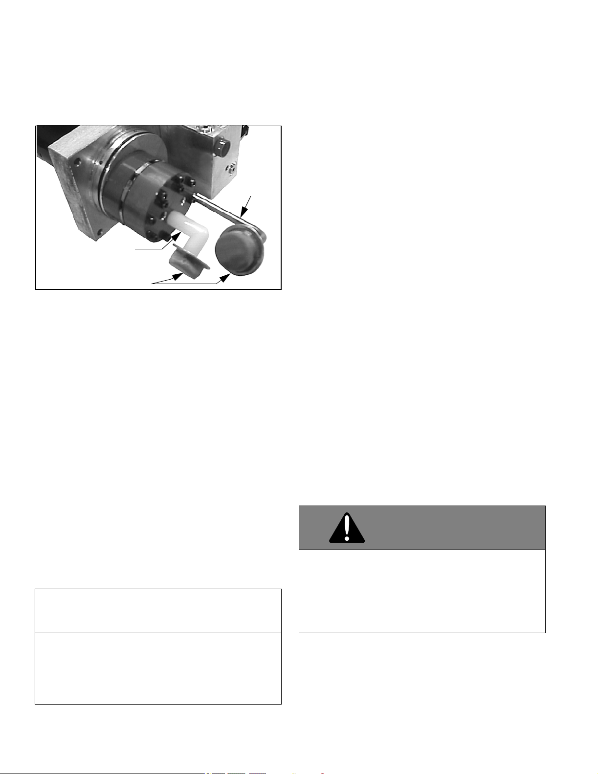
4. Remove the pin from the cylinder lock clamp.
5. Position the cylinder lock clamp around the exposed
(chrome) portion of the lift cylinder with the open side of
the cylinder lock up. Install the pin. (See Figure 1-13).
Figure 1-13
6. Lower the plow so that cylinder lock clamp is tight
against cylinder.
WARNING
Make sure that upper hitch pins are engaged
before moving truck. Hitch pins not fully
engaged could result in the plow separating
from the truck.
FAILURE TO FOLLOW CAN RESULT IN DEATH
OR SERIOUS INJURY.
PIN HANDLE
FORWARD
UPPER HITCH PIN
BELL CRANK
LIFT LINK
UPPER PIN
HANDLE
LOWER PIN
HANDLE
JACK STAND
WARNING
Insert cylinder lock clamp when plow is not
engaged in plowing operations. Failure to do so
can allow plow to drop to unsafe position.
FAILURE TO FOLLOW CAN RESULT IN DEATH
OR SERIOUS INJURY.
WIRE LOCK PIN
LIFT
LINK
A-FRAME BOTTOM
BELL
CRANK
CYLINDER
LOCK
CLAMP
CYLINDER
ROD

9
Removing Snow Plow From Vehicle
Choose a location for the plow storage, which will allow
the plow to be removed from the vehicle and not be
moved after removal. Also, choose a location that will not
allow the plow stand to sink into the ground. A dry,
protected area is recommended.
1. Lower plow to the ground, put vehicle in park, turn off
the engine and set the parking brake.
2. Disengage lower jack stand pin by pulling on handle.
Lower the jack stand and engage the top pin by pushing
on the handle. Make sure pin is engaged in hole by
rotating jack stand back and forth. (See Figure 1-14)
Figure 1-14
3. Turn Down Pressure ON and then OFF.
4. Push pin handles toward truck to unlock main pins.
(See Figure 1-15)
Figure 1-15
5. Rotate jack stand down and raise A-frame by
pressing the up button. (See Figure 1-16)
Figure 1-16
6. Disconnect power and control harnesses, replace
protective caps, and back truck away from plow.
BELL
CRANK
JACK
STAND
LIFT LINK
UPPER PIN
HANDLE
PIN HANDLE
STRAIGHT OUT
PIN HANDLE
STRAIGHT OUT

10
General
• Before operating, perform a through visual
inspection of the equipment. Look for fluid leaks,
cracked, bent or broken components, loose nuts,
bolts or attachments and proper fluid levels.
• A clean system is essential to long pump life and
proper performance.
• When adding oil to the reservoir, wipe area around
the filler port clean before removing the breather cap.
Use clean oil and a clean funnel (DO NOT use a cloth
or rag to strain the oil).
IMPORTANT: Sno-Way supplies type 5606 Sno-Way
Hydraulic Oil with the unit from the factory. If
additional oil is added it must be compatible with
Sno-Way oil. If another type of oil has been used in
the system the same type of oil must be used for
topping off the system. Improper hydraulic fluid can
cause operating problems in cold weather.
• Do NOT use synthetic oil.
• Oil must contain an anti-foam additive.
• Ensure all electrical connections are clean and
tight.
• To prevent rust from forming, clean and repaint
exposed metal surfaces.
• NEVER operate the equipment with the protective
covers or guards removed.
Break In Period
The plow will go through a break in period during which
the A-frame and swing frame will settle in. After 15-20
hours of operation check for free play of the A-frame and
swing frame pivot.
1. Raise the plow and insert a jack stand under the A-
frame.
2. Push down on end of blade as far as it will go on the
right or left side. Measure and record the distance from
the ground to the bottom edge of the wear strip.
3. Pull upwards on the same end of the plow as far as it
will go. Measure and record the distance from the ground
to the bottom edge of the wear strip.
4. Subtract the two measurements. If the number is
greater than 1-1/2" then the free play needs to be
adjusted.
To Remove Excessive Free Play
1. Tighten the pivot bolt nut (typically 1/6 to 1/3 turn, one
or two flats).
Periodic Inspection
After every 20 hours of operation perform the following
inspections:
1. Inspect plow assembly including sub frame for any
damage or excessive wear. Replace parts as necessary.
2. Inspect all fasteners (Plow & Truck Mount) to insure
they are properly tightened. Re-tighten loose fasteners to
the proper torque. Loose fasteners on the Bellcrank,
Pump Platform to A-Frame, Power Unit to the Pump
Platform, and Truck Mount must have the locknuts
replaced and tightened while using Sno-Way thread
locker 96115529. (Refer to torque specification chart in
this manual).
3. Apply a small amount of light oil to: Quick-tatch pin
and handle assemblies, pivot pins between the blade and
swing frame, and pivot pins at lift and swing cylinders.
Also lubricate jackstand pins. (See Figure 2-1)
Figure 2-1
WARNING
Before servicing plow, lower plow to the
ground or onto cylinder lock clamp and
disconnect main power harness.
FAILURE TO FOLLOW CAN RESULT IN DEATH
OR SERIOUS INJURY.
SWING
PIVOTS
CYLINDER
QUICK-TATCH
PIN / HANDLE
JACKSTAND PIN
LIFT
LINKAGE
PIVOTS
LIFT
CYLINDER
PIVOTS
BLADE
PIVOT
PINS
MAINTENANCE

11
Plow Storage
When storing the plow for long periods of time use the
following guidelines.
1. If the plow will not be stored on pavement, place a
board under the jack stand to prevent it from sinking into
the ground.
2. To prevent corrosion, coat the exposed portion of the
cylinders with light grease.
3. Grease all pivot points.
4. Fill hydraulic reservoir to the fill line to minimize
trapped air.
5. Place dielectric grease on the terminals of all
electrical plugs, including those under pump cover. Make
sure protective caps are in place or connectors are
plugged together.
6. Check and replace any worn or damaged
components, such as cutting edges, deflectors, and
bushings.
7. For additional protection, use a 99101213 plow parka
cover.
Polycarbonate Blade Care
• DO NOT use abrasive or highly alkaline cleaners on
polycarbonate blade.
• Never scrape polycarbonate blade with squeegees,
razor blades or other sharp instruments.
• Benzene, gasoline, acetone or carbon tetrachloride
should never be used on polycarbonate blade.
• DO NOT clean polycarbonate blade in hot sun or at
elevated temperatures.
Polycarbonate Blade Cleaning
Instructions
Wash with a mild soap or detergent and luke-warm water
using a clean cloth or soft sponge. Dry thoroughly with a
chamois or moist cellulose sponge to prevent water spots.
Special Fasteners Torques and
Requirements
IMPORTANT: Incorrectly securing fasteners may
result in incorrect operation, excessive wear, and
early failure of plow components. It may also void
your warranty.
• ALWAYS check to make sure you are using the
correct torque specification for the fastener you
are using.
• DO NOT use any lubricants on the threads of any
fastener.
Standard Fasteners
The Torque Specifications Chart on page 27 of this
manual should be used as the guide for fastener torque
requirements for most standard fasteners used on the
plow.
Standard fasteners with special torque requirements will
be noted in assembly or service instructions pertaining to
the specific piece of equipment.
Hydraulic Fittings
Hydraulic fittings with locknuts should be assembled with
at least three full turns of the fitting in the port and then the
locknut should be tightened to 27 lb-ft.
Hydraulic fittings with 37 degree flare end swivels should
be torqued to 18-20 lb-ft.
Fluid Requirements
IMPORTANT: Sno-Way supplies type 5606 Sno-Way
Hydraulic Oil with the unit from the factory. If
additional oil is added it must be compatible with
Sno-Way oil.
It is recommended that the fluid in the hydraulic system be
changed once a season.
NOTE: Type 5606 oil is rated to -60 deg. F, when Type
5606 is not available Exxon UNIVIS J13 or equivalent
may be used.
Do NOT use synthetic oil.
Oil must contain an anti-foam additive.
NOTICE
• Using the proper oil increases the life
expectancy of the most critical part of your
plow; the hydraulic power unit.
• Failure to use the proper oil can cause
extensive damage to the power unit, seals and
hydraulic cylinders.
• Improper oil can cause operating problems and
poor performance in cold weather.
FAILURE TO FOLLOW COULD LEAD TO
PROPERTY DAMAGE.

12
Changing Oil and Cleaning Filter Screen
NOTE: Change oil and clean filter screen at the begin-
ning of every season. This will help ensure maximum life
and maximum performance from the pump assembly.
1. Move plow to a clean, dry area with a solid surface.
Lower the plow to the ground, put vehicle in park, turn off
the engine, and set the park brake. Turn off the plow
controller.
2. To prevent inadvertent short circuit or electrical
shock, disconnect the power harness and
communication harness at the vehicle bumper.
3. Remove the two screws at the lower back of the
pump cover. Pull the back of the pump cover off the rear
tabs and rotate the cover slightly forward. Push the cover
off the front tabs and remove. (See Figure 2-2)
Figure 2-2
4. Remove the filler/breather cap from the reservoir.
(See Figure 2-3)
Figure 2-3
5. Using a suction gun or similar tool, remove the oil
from the reservoir.
NOTE: Be careful to avoid contacting and damaging the
filter screen while removing oil.
6. Remove the lift cylinder hoses from the valve block.
Remove the swing cylinder hoses from the fitting in the
valve block. Mark hoses before removal to be certain
they are reinstalled in the correct location.
7. Place the hoses in a container to catch oil expelled
from cylinders. Cycle the lift cylinder by disconnecting
hitch pins and pushing and pulling on lift bar. Cycle swing
cylinders by disconnecting from swing frame and pushing
and pulling on cylinder rod.
8. Reconnect swing cylinders and install hitch pins.
WARNING
• Allow the system to cool down before draining
oil or handling system components. Burns can
result from contact with hot oil.
• Never disconnect any hydraulic line or fitting
with the plow in the raised position. Always
lower the plow and relieve pressure before
removing any lines or caps.
FAILURE TO FOLLOW CAN RESULT IN DEATH
OR SERIOUS INJURY
WARNING
Ensure engine is OFF and set parking brake
before working on plow. Vehicle movement,
equipment failure or inadvertent operation of
the control switches during maintenance could
result in serious injury
FAILURE TO FOLLOW CAN RESULT IN DEATH
OR SERIOUS INJURY.
TWO
FRONT
TABS
TWO
SCREWS
FILLER
CAP
13
9. Loosen the band clamp, which holds the reservoir to
the pump assembly. Pull and twist the reservoir until it
separates from the pump assembly. Be careful not to
damage the filter screen. (See Figure 2-4)
10. Note the position of the reservoir oil pick-up tube and
be sure the tube is in the same position when the filter is
removed and installed. (See Figure 2-4)
Figure 2-4
11. Pull the filter screens off the return and suction tubes
(hold it by the metal cover, not the screen) and clean.
Blow-dry with low-pressure air from the inside. (See
Figure 2-4).
12. Carefully re-install the filter screens. Use care when
handling the screens to avoid damage.
13. Visually check that the pickup tube and filter are in
the proper orientation (See Figure 2-4). If not, rotate the
pickup tube until the tube and filter are in the proper
orientation.
14. Clean the inside and outside of the reservoir.
15. Inspect the O-ring seal for damage. Replace if
needed. Before installing, lubricate with fresh oil, and
reinstall reservoir carefully to avoid damaging the O-
Ring.
16. Tighten band clamp that holds the reservoir to power
unit.
17. Reconnect hydraulic fittings and hoses in their
correct position and torque to 20-25 lb-ft. If unit utilizes O-
Ring and jam nut type connectors tighten jam nut to 15-
20 lb-ft.
18. Fill the hydraulic reservoir with type 5606 hydraulic
fluid until the fluid registers full on the oil level mark on
reservoir.
NOTE: Vehicle must be parked on level ground and plow
must be in lowered position in order to properly check the
reservoir level.
19. Refer to controls manual and cycle plow to remove
air from hydraulic system. Refill reservoir as needed.
20. Operate system and check for leaks. Repair and
replace components as necessary. Install pump cover.
Cutting Edge
IMPORTANT: Cutting edge MUST be replaced when
it is worn to the bottom edge of the plow frame.
1. Raise the plow to full up position.
2. Place a jack stand under both ends of the blade
bottom rail.
3. With the Down Pressure Hydraulic System OFF,
lower plow until firmly resting on jack stands.
4. The blade skin must be retained prior to removing
cutting edge. This can be done using a pair of 6" C-
clamps located at the center of the curved portion of the
blade.
5. With an assistant, remove hardware and worn
wearstrip from plow.
6. Insert two carriage bolts, one on each end of the
blade, through the cutting edge and blade. Loosely install
two locknuts.
7. Insert the remaining carriage bolts and loosely install
locknuts on each bolt.
8. Beginning on either side, tighten all nuts securely.
NOTICE
• Do Not use Teflon tape or pipe dope on hydraulic
fittings. These can dislodge and jam valves in the
hydraulic system.
FAILURE TO FOLLOW COULD LEAD TO
PROPERTY DAMAGE.
FILTER
SCREEN
PICK-UP
TUBE
RETURN
TUBE
WARNING
The bottom of the cutting edge can be very
sharp. Whenever handling a cutting edge, work
with an assistant and wear suitable protective
gloves to avoid serious injury.
FAILURE TO FOLLOW CAN RESULT IN DEATH
OR SERIOUS INJURY.

14
Plow Shoe Adjustment
1. Raise plow to full up position.
2. Support blade with a jack.
3. Turn vehicle ignition switch and plow control OFF and
apply emergency brake.
4. Adjust shoe assemblies by removing shoe mounting
lynch pin and adding or subtracting washers on the top or
bottom of the shoe-mounting bracket. (See Figure 2-5).
Figure 2-5
5. After the plow shoe position is properly adjusted
place washer on the shoe stem - above the plow shoe
mounting bracket and below the retaining lynch pin - to
remove all up and down movement of the plow shoe in
the bracket. Failure to do so will result in excessive wear
of the holes in mounting bracket or bending of the plow
shoe stem.
IMPORTANT: Snap lynch pin ring over so that it
contacts the pin. If ring does not contact lynch pin,
rotate the pin and reverse the direction of the ring. If
the ring does not contact the pin it is not locked and
could fall out.
Trip Spring Adjustment
See "Mechanical Installation" on page 5.
Blade Stop Replacement
Replace the blades stop at least every 3 years by
following in reverse order: the steps under "Assemble
Blade, Swing Frame, and Trip Springs" on page 5 in the
Mechanical Installation section.
Emergency Plow Raise
If your snowplow becomes inoperable for any reason,
follow the instructions below to raise the plow for transport
to your nearest Sno-Way Dealer.
1. Move truck to level hard ground.
2. Place a jack under the swing frame as close to the A-
frame as possible.
3. Raise jack until the A-frame is at approximately 30
degrees with the ground.
4. Make sure the plow and jack are stable. Place a jack
stand or wood blocking under the A-frame to prevent the
plow from suddenly dropping.
5. Install cylinder lock clamp. (See "Installing The
Cylinder Lock Clamp" on page 8.)
6. Remove Jack and Jack stand.
7. Drive to your nearest Sno-Way dealer for service.
WASHERS
PIN
WARNING
Failure to place a jack stand under the plow
could result in the plow rapidly falling.
FAILURE TO FOLLOW CAN RESULT IN DEATH
OR SERIOUS INJURY.

15
Operating Class
The 22 Series 2 Sno-Way plow is specifically designed for
applications on light duty trucks and SUVs.
NOTE: The loaded vehicle, including any ballast weight
and optional equipment, must not exceed the Gross
Vehicle Weight (GVW) or front or rear Gross Axle Weight
(GAW) ratings specified on the Safety Compliance Certi-
fication Label located on the driver's side door opening.
For additional information, refer to your dealer and the
Sno-Way Application Guide for proper vehicle applica-
tions.
Before the Season Begins
1. Inspect plow vehicle’s electrical system for proper
operation.
2. Inspect plow assembly including sub frame for any
damage or excessive wear. Replace parts as necessary.
3. Inspect all fasteners to insure they are properly
tightened. Re-tighten loose fasteners to the proper torque
(Refer to torque specification chart in this manual).
4. Apply a small amount of light oil to: Quick-tatch pin
and handle assemblies, pivot pins between the blade and
swing frame, and pivot pins at lift and swing cylinders.
Also lubricate jackstand pins. (See Figure 2-1).
5. Clean and repaint any exposed metal parts with
corrosion resistant enamel.
6. Check free play between the a-frame and swing
frame pivot. Adjust if necessary. (See "Break In Period"
on page 10).
7. Check the oil level and repair any oil leaks. (See
"MAINTENANCE" on page 10).
8. Inspect electrical connectors. Make sure the contacts
are clean, and apply a small amount of dielectric grease.
9. If ballast is required, position and secure ballast
behind rear wheels, for optimum performance.
Transporting Vehicle With Plow Attached
1. Always install the cylinder lock clamp when the plow
is raised and the operator is not engaged in plowing
operations. See "Installing The Cylinder Lock Clamp" on
page 8.
2. Position the blade out of the beam path of the
headlights before driving.
3. Do not exceed 45 M.P.H. when driving with the
snowplow attached. Braking distance is increased and
handling impaired at speeds above 45 M.P.H.
4. Reduce speed when crossing railroad tracks or when
road conditions deteriorate.
5. Never change blade angle or height while driving.
6. Inspect plow and attaching hardware for damage
before transporting or plowing.
Plowing Like A Pro
NOTICE
• Remove the plow when driving extended
distances at temperatures above 40 deg. F, the
plow blocks enough airflow to cause it to overheat
at temperatures above 40 deg. F.
FAILURE TO FOLLOW COULD LEAD TO
PROPERTY DAMAGE.
WARNING
Check your local laws with regards to
transporting plow mounted to vehicle on public
roads.
FAILURE TO FOLLOW CAN RESULT IN DEATH
OR SERIOUS INJURY.
WARNING
Wear your seat belt! Contact with a hidden
obstruction can cause serious personal injury
from bodily contact within the vehicle cab or
whiplash from sudden stops.
FAILURE TO FOLLOW CAN RESULT IN DEATH
OR SERIOUS INJURY.
WARNING
• Never exceed 10 m.p.h. when plowing! Serious
personal injury can result, as well as damage
to equipment and property, if an unseen
obstruction is encountered while plowing.
• Never plow with your head protruding from the
vehicle side window. Serious head or neck
injuries can result from sudden stops or
coming into contact with tree branches, signs
or other stationary objects.
FAILURE TO FOLLOW CAN RESULT IN DEATH
OR SERIOUS INJURY.
PLOWING OPERATION

16
NOTE: The air bag is factory set to deploy at a certain
acceleration level. The air bag will deploy with the plow
attached if an obstruction is hit with enough force to
reach this level. Always plow within the recommended
plowing speeds and know the area you are plowing to
avoid any obstructions.
NOTE: For better clean up of hard packed snow; raise
the plow shoes so that the cutting edge of the blade
comes into direct contact with pavement. Use the lowest
possible gear to place maximum power behind the cut-
ting edge.
For instructions on using the plow controller to manipulate
the plow see the manual included with your plow control
package.
1. Become familiar with the area to be plowed and mark
potential hazards before the snow falls. Many immovable
objects cannot be seen when covered with snow.
Developing a plan early can save valuable time and
equipment damage. Allow sufficient room to pile snow,
out of the traffic area, with enough space for when the
next storm comes.
2. Plow with the storm. The "Pros" are out early
removing only several inches at a time. Allowing snow to
accumulate to unmanageable levels can cause removal
problems and wear and tear on equipment. The plow is
not a "Ram" or a "Bulldozer". If used properly, it will give
many years of safe and reliable service.
3. Research municipal ordinances for restrictions on the
disposal of snow. Many municipalities do not allow snow
to be placed in or moved across roads or highways.
4. Research state department of transportation rules on
maximum width restrictions for snow plows. Certain
blades may require permits.
Using The Down Pressure (DP) Hydraulic
Systems
The DP system was designed for removing hard packed
snow from hard surfaces that has been driven on prior to
plowing.
The system should be turned OFF when plowing surfaces
such as gravel, dirt, sand, etc., to prevent cutting into the
surface.
Activating the system applies down pressure to the down
pressure side of the lift cylinder. This down pressure will
force the cutting edge through hard packed snow. If down
pressure decreases as a result of a low spot, more down
pressure will be applied to the lift cylinder. When a high
spot is encountered the down pressure will be relieved to
allow the plow to follow the contour without lifting the front
of the truck.
Clearing Driveways
1. Head into driveway with the blade angled to move
snow away from buildings. Continue to widen the drive
path by rolling snow away from buildings on successive
passes.
2. If there is a garage at the end of the driveway, plow to
within several vehicle lengths of the garage and push the
snow off the driveway.
3. Raise the blade and drive through the snow up to the
garage. Drop the blade and "Back Drag" the snow 1-1/2
vehicle lengths back. Repeat as necessary.
4. Back the vehicle to garage door and plow forward
toward street, removing the remaining snow.
NOTICE
Excessive stacking of snow causes undo
stress to the snowplow and vehicle. Repeated
loading of this nature may result in the failure
of plow components designed to protect the
snowplow and vehicle from major damage.
FAILURE TO FOLLOW COULD LEAD TO
PROPERTY DAMAGE.

17
Introduction
Whenever service is necessary, your local dealer knows
your plow best and is interested in your complete
satisfaction. Return your snowplow to your local dealer for
maintenance service or any other assistance you may
require. If you are unable to do so, this troubleshooting
guide should help you determine the problem. However,
before attempting the servicing of your plow, you should
possess good mechanical abilities and a total
understanding of the mechanism.
PLEASE: Before calling parts and service personnel be
certain that:
1. You have read this guide carefully and are certain
that all of the suggestions pertaining to your problem
have been attempted.
2. You have the following available:
A. Date snowplow was originally installed
B. Power Pack Serial Number
This information should be recorded on page 2 of this
Owners Manual.
Troubleshooting Guide - Quick Reference
1. Check vehicle electrical system for proper operation.
2. Check all wiring to be sure that battery terminals are
clean and connections to battery, fuse, solenoid, and all
connectors on plow harness are clean and tight.
3. Check for external leakage at cylinders, hoses, and
power unit.
4. Check the voltage at the coils which operate solenoid
valves. For proper operation, Pro Control system
solenoid coils require a minimum of 10 volts DC.
5. Check oil level in hydraulic system reservoir.
WARNING
First read all warning instruction, the safety
messages, and directions before attempting
any adjustments or repairs to your unit!
FAILURE TO FOLLOW CAN RESULT IN DEATH
OR SERIOUS INJURY.
TROUBLESHOOTING GUIDE
PROBLEM PROBABLE CAUSE CORRECTIVE ACTION
Motor will not run/
motor runs slow
Fuse Blown Check the circuit breaker / 250A fuse at your battery as well as the 10A fuse
on the pump harness. If either fuse has blown check over all electrical wiring
to determine why the fuse blew and replace fuse
Motor solenoid failed Replace Motor solenoid.
Motor seized Remove and replace motor, torque motor bolts between 50 to 60 inch
pounds.
Motor brushes worn Replace motor.
Seal between motor and
pump damaged allowing
oil to enter motor housing
Remove the motor. Drain oil from the reservoir. Loosen the clamp and
remove the reservoir. Remove the 4 Allen screws and remove the pump
from the base block. Remove pump seal and replace. If the motor can be
salvaged, clean out motor and reassemble. If the motor can not be salvaged
replace motor.
Motor continues to
run and will not shut
off
Wires shorted out Check all wires starting at solenoid working your way back to the vehicle.
Solenoid shorted
internally
Replace solenoid.
TROUBLESHOOTING

18
Blade will not lift
(motor runs)
Hydraulic fluid level low Fill hydraulic fluid up to the fill line on the reservoir using Sno-Way hydraulic
fluid.
Improper main system
pressure relief valve
setting
Using a 3000 psi gauge plumbed into the gauge port (GP), run plow over
relief. Adjust main pressure relief screw to the proper main system pressure
for the series of plow. This can be found in the back of your owners manual
or online at SNOWAY.com.
Breather cap plugged Remove and replace breather cap.
Coil on valve (F) Check if there is magnetism on coil (F). If there is not swap coil with the coil
(A). If the problem moves to the angle function the coil is bad and needs to
be replaced.
Lower valve (F) stuck Check valve to make sure there is magnetism on the "F" coil. Remove the
"F" valve and swap it with the "E" valve. If the blade lifts your valve was stuck
closed. Remove and replace the valve.
Raise cylinder binding Check all linkages in the bell crank area. Replace and damaged
components.
Pick up tube filter plugged Remove hydraulic fluid from the tank. Remove the tank and observe the pick
up tube screen. Clean or replace if necessary.
Worn/failed pump Using a 3000 psi gauge plumbed into the gauge port (GP), run plow over
relief. Adjust main pressure relief screw. If the pressure will not raise and the
angle functions work remove hydraulic fluid and tank. Replace pump.
Pick up tube is not
submerged in fluid
Remove hydraulic fluid and tank. Turn pick up tube so it is angled down to
the bottom of the tank.
Down pressure valve (E)
stuck open
Check valve to make sure there in not magnetism on the "E" coil. Remove
the "E" valve and swap it with the "F" valve. If the blade lifts, your valve was
stuck open. Replace the valve.
Raise Valve (C) not
functioning
Check "C" coil for magnetism. Remove the "C" valve and inspect. Make sure
the lower part of the valve moves free and there is no debris causing the
valve to stick. If stuck and cant be freed up replace valve.
TROUBLESHOOTING GUIDE
PROBLEM PROBABLE CAUSE CORRECTIVE ACTION

19
Blade lifts slowly Hydraulic fluid level low Fill hydraulic fluid up to the fill line on the reservoir using Sno-Way hydraulic
fluid.
Breather cap plugged Remove and replace breather cap.
Improper main system
pressure relief valve
setting
Using a 3000 psi gauge plumbed into the gauge port (GP), run plow over
relief. Adjust main pressure relief screw to the proper main system pressure
for the series of plow. This can be found in the back of your owners manual
or online at SNOWAY.com.
Pick up tube filter plugged Remove hydraulic fluid from the tank. Remove the tank and observe the pick
up tube screen. Clean or replace if necessary.
Improper oil viscosity for
outside air temperature/
Ice in hydraulic tank
Change oil with Sno-Way hydraulic fluid.
Weak system pump Using a 3000 psi gauge plumbed into the gauge port (GP), run plow over
relief. Adjust main pressure relief screw. If the pressure will not raise and the
angle functions work remove hydraulic fluid and tank. Replace pump.
Low vehicle battery
voltage
Check voltage at both the battery and at the solenoid during function. The
battery may show 12V when the plow is not under load. If the voltage drops
below 9V when operating the plow, trouble shoot power system on your
vehicle.
Plow lifts but does
not hold - New plow
first action
Dirt in check valve Cycle raise and lower system to flush debris.
Dirt in lower valve (B) Cycle raise and lower system to unstick valve.
Plow lifts but does
not hold - second
action
Dirt or Debris in check
valve
Cycle raise and lower system to unstick valve if this does not work replace
valve.
Lower valve (B) stuck Check valve to make sure there in not magnetism on the "B" coil. Remove
the "B" valve and swap it with the "F" valve. If the blade lifts your valve was
stuck open. Replace the valve.
Seals, O-ring(s) on lower
valve (B) damaged
Remove the lower valve (B) and inspect the O-rings to see if they are
damaged. If damaged replace the O-ring if there is one available. If not
replace the valve.
Piston seals leaking
(Internal) on raise cylinder
Raise the plow up in the air and support the blade with a hydraulic floor jack.
Remove the hose off of the rod side of the lift cylinder. Slowly lower the floor
jack and watch to see what direction the fluid flows from the lift cylinder. If the
fluid sucks into the lift cylinder the seals are good. If the fluid flows out of the
lift cylinder, fluid is leaking past the seals and the cylinder needs to be
replaced.
TROUBLESHOOTING GUIDE
PROBLEM PROBABLE CAUSE CORRECTIVE ACTION
Table of contents
Other Sno-Way Snow Blower manuals


