Sno-Way 26V Series Operating instructions

97102169A
INSTALLATION &
OWNER’S MANUAL
26V SERIES SNOW PLOW
WITH SERIAL NUMBERS AFTER:
26V100000
Sno-Way®, Down Pressure® and EIS®are registered trademarks of Sno-Way International, Inc.
ProControl™, MegaBlade™, V-Wing™, Revolution™and MaxAdjust™are trademarks of Sno-Way
International, Inc.
©2019 Sno-Way®International

1
TABLE OF CONTENTS
Page
INTRODUCTION ......................................................................................................... 2
SAFETY ...................................................................................................................... 3
INSTALLATION INSTRUCTIONS............................................................................... 4
General .............................................................................................................. 4
Electrical Installation ........................................................................................ 4
Mechanical Installation..................................................................................... 5
Blade Level Adjustment ................................................................................... 9
Mounting Snow Plow To Vehicle ................................................................... 10
Installing The Cylinder Lock Clamp .............................................................. 13
Removing Snow Plow From Vehicle ............................................................. 13
MAINTENANCE ........................................................................................................ 15
General ............................................................................................................ 15
Periodic Inspection......................................................................................... 15
Special Fasteners Torques and Requirements ............................................ 16
Hydraulic Fittings ........................................................................................... 16
Hydraulic Cylinders ........................................................................................ 16
Electrical Quick Disconnect Plugs................................................................ 16
Fluid Requirements ........................................................................................ 16
Changing Oil and Cleaning Filter Screen ..................................................... 17
Cutting Edge Replacement ............................................................................ 18
Plow Shoe Adjustment................................................................................... 19
Trip Spring Adjustment .................................................................................. 19
PLOWING OPERATION ........................................................................................... 20
Operating Classes .......................................................................................... 20
Before The Season Begins ............................................................................ 20
Transporting Vehicle With Plow Attached .................................................... 20
Plowing Like A Pro ......................................................................................... 21
Using The Down PressureTM (DP) Hydraulic System.................................. 21
Clearing Driveways......................................................................................... 22
Clearing Parking Lots..................................................................................... 22
TROUBLESHOOTING .............................................................................................. 23
Introduction..................................................................................................... 23
Troubleshooting Quick Reference - General................................................ 23
Troubleshooting Guide ................................................................................... 23
THEORY OF OPERATION........................................................................................ 27
Hydraulic Controls.......................................................................................... 27
Electro-Hydraulic Controls ............................................................................ 27
Raise Mode of Operation ............................................................................... 27
Lower Mode of Operation - Gravity Down and Float ................................... 28
Lower Mode of Operation - Down PressureTM Hydraulic (DP) System ..... 28
Wing Angling Mode of Operation - Independent Wing Angling ................. 28
Combination Wing Angling............................................................................ 29
Fuse ................................................................................................................. 29
Power Unit Components ................................................................................ 29
HYDRAULIC SCHEMATIC ....................................................................................... 30
WIRING SCHEMATIC - With S.N. After: 26V100000 .............................................. 31
POWER UNIT SOLENOID FUNCTION, WIRING AND LOCATION......................... 32
MAIN WIRING HARNESS SCHEMATIC EIS® (Energy Interruption SystemTM) . 33
TORQUE SPECIFICATIONS ................................................................................... 34
2
This manual was written for the assembly, installation and
maintenance of your new Sno-Way plow. Most
importantly, this manual provides an operating plan for
safe use. Refer to the Table of Contents for an outline of
this manual.
Please keep this manual with your machine at all times as
reference material and so it can be passed on to the next
owner if the machine is sold.
We require that you read and understand the contents of
this manual COMPLETELY, especially the chapter on
SAFETY, before attempting any procedure contained in
this manual.
The Society of Automotive Engineers has adopted
this SAFETY ALERT SYMBOL to pinpoint character-
istics that, if NOT carefully followed, can create a
safety hazard. When you see this symbol in this man-
ual or on the machine itself, BE ALERT!, your per-
sonal safety and the safety of others, is involved.
• Defined below are the SAFETY ALERT messages
and how they will appear in this manual.
NOTE: Additional information concerning the equipment
or the procedure that may or may not be contained else-
where in this manual.
BE AWARE! It is illegal to remove, deface or other-
wise alter the safety decals mounted on this equip-
ment.
Record the Power Pack Model Number, Power Pack
Serial Number, Controller Serial Numbers, Blade Model
Number, Blade Serial Number and the Pump Serial
Number in the space provided below as a handy record
for quick reference. The Power Pack Serial Number is
located on the Lower Light Lift Bar (driver’s side), the
blade serial number is located on one of the middle ribs of
the blade. These plates contain information that your
Dealer needs to answer questions or to order
replacement parts, if needed, for your unit.
We reserve the right to make changes or improve the
design or construction of any part(s) without incurring the
obligation to install such parts or make any changes on
any unit previously delivered.
Graphics and illustrations may be used which may show
equipment and/or options not included in every
installation without incurring the obligation to install such
parts or make changes on units previously delivered.
Sno-Way Service Parts Manuals are available on-line or
at your authorized Sno-Way dealer. Request part number
97102170 & 97101915 for the 26V Series Snow Plow.
Factory contact information is available at
www.snoway.com.
WARNING
FAILURE TO FOLLOW CAN RESULT IN INJURY
OR DEATH.
CAUTION
Information, that if not carefully followed, can
cause injury or damage to equipment!
DEALER
NAME
PHONE ( ) –
ADDRESS
CITY STATE ZIP
(FILL IN)
ORIGINAL PURCHASER
NAME
PHONE ( ) –
ADDRESS
CITY STATE ZIP
(FILL IN)
NAME PLATE DATA
POWER PACK MODEL NUMBER
BLADE SERIAL NUMBER
PUMP SERIAL NUMBER
(FILL IN)
POWER PACK SERIAL NUMBER
CONTROLLER SERIAL NUMBERS:
BLADE MODEL NUMBER
(Located on Blade Frame)
(Located on Lower Light Lift Bar - Drivers Side)
TRANSMITTER S.N.
RECEIVER S.N.
INTRODUCTION

3
BEFORE ATTEMPTING ANY PROCEDURE IN THIS
BOOK, READ AND UNDERSTAND ALL THE SAFETY
INFORMATION CONTAINED IN THIS SECTION. IN
ADDITION, ENSURE ALL INDIVIDUALS WORKING
WITH YOU ARE ALSO FAMILIAR WITH THESE
SAFETY PRECAUTIONS.
For your safety Warning and Information Decals have
been placed on this product to remind the operator
to take safety precautions. It is important that these
decals are in place and are legible before operation
begins. New decals can be obtained from Sno-Way or
your local dealer.
REMEMBER The careful operator is the best
operator. Most accidents are caused by human error.
Certain precautions must be observed to prevent the
possibility of injury to operator or bystanders and/or
damage to equipment.
NEVER operate Plow when under the influence of
alcohol, drugs or other medications that could hamper
your judgement and reactions. An accident may result in
serious injury or death to other persons or yourself.
ALWAYS operate vehicle in a well-ventilated area. The
carbon monoxide in exhaust gas is highly toxic and can
cause serious injury or death.
NEVER allow hands, hair or clothing to get near any
moving parts such as fan blades, belts and pulleys.
Never wear neckties or loose clothing when working on
the vehicle.
NEVER wear wrist watches, rings or other jewelry when
working on the vehicle or individual equipment. These
things can catch on moving parts or cause an electrical
short circuit that could result in serious personal injury.
ALWAYS wear safety goggles when working on the
vehicle to protect your eyes from battery acid, gasoline,
and dust or dirt from flying off of moving engine parts.
ALWAYS be aware of and avoid contact with hot
surfaces such as engine, radiator, and hoses.
ALWAYS wear safety glasses with side shields when
striking metal against metal! In addition, it is
recommended that a softer (non-chipable) metal material
be used to cushion the blow. Failure to heed could result
in serious injury to the eye(s) or other parts of the body.
NEVER allow children or unauthorized person to
operate this unit.
NEVER exceed 45 m.p.h. when snow plow is attached
to vehicle. Braking distances may be increased and
handling characteristics may be impaired at speeds
above 45 m.p.h.
ALWAYS lock the vehicle when unattended to prevent
unauthorized operation of the plow.
ALWAYS check the job site for terrain hazards,
obstructions and people.
NEVER exceed 10 m.p.h. when plowing. Excessive
speed may cause serious injury and damage of
equipment and property if an unseen obstacle is
encountered while plowing.
ALWAYS position blade so it does not block path of
headlamps beam. Do not change blade positions while
traveling. An incorrect plow position blocking headlamp
beam may result in an accident.
ALWAYS check surrounding area for hazardous
obstacles before operating this unit.
ALWAYS inspect the unit periodically for defects. Parts
that are broken, missing or plainly worn must be replaced
immediately. The unit, or any part of it should not be
altered without prior written approval of the manufacturer.
ALWAYS insert the cylinder lock when plow is not in
use. If the cylinder lock is not installed, the plow blade
could inadvertently drop and cause serious injury.
ALWAYS shut off the vehicle engine, place the
transmission in Neutral or Park, turn the ignition switch to
the “OFF” position and firmly apply the parking brake of
the vehicle before attaching or detaching the blade from
the vehicle or when making adjustments to the blade.
ALWAYS inspect lift system bolts and pins whenever
attaching or detaching the plow, and before traveling.
Worn or damaged components could result in the plow
dropping to the pavement while driving, causing an
accident.
ALWAYS keep hands and feet clear of blade and A-
Frame when attaching or detaching plow.
NEVER stand between the vehicle and blade or directly
in front of blade when it is being raised, lowered or
angled. Clearance between vehicle and blade decreases
as blade is operated and serious injury or death can
result from blade striking a body or dropping on hands or
feet.
NEVER work on the vehicle without having a fully
serviced fire extinguisher available. A 5 lb or larger CO2
or dry chemical unit specified for gasoline, chemical or
electrical fires, is recommended.
NEVER smoke while working on the vehicle. Gasoline
and battery acid vapors are extremely flammable and
explosive.
NEVER use your hands to search for hydraulic fluid
leaks; escaping fluid under pressure can be invisible and
can penetrate the skin and cause a serious injury! If any
fluid is injected into the skin, see a doctor at once!
Injected fluid MUST BE surgically removed by a doctor
familiar with this type of injury or gangrene may result.
REMEMBER it is the owner’s responsibility for
communicating information on the safe use and
proper maintenance of this machine.
SAFETY
4
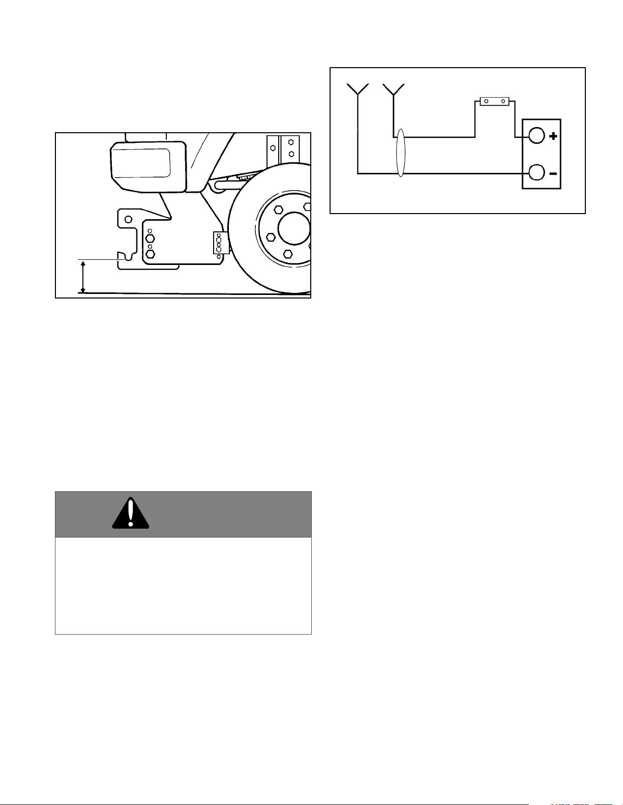
General
Install the subframe on the vehicle using the instructions
supplied with the subframe package. The pin height
should be 8" - 10" off the ground. (See Figure 1-1.)
Figure 1-1
Electrical Installation
1. Remove the battery power harness and power
harness parts bag from the power pack carton.
NOTE: Take extra time needed to plan the routing of wir-
ing harnesses. Make sure harnesses do not interfere
with, or contact, any moving parts and route wires away
from excessive heat areas. Read all the instructions
carefully to ensure a safe and professional installation.
2. Mount the fuse holder near the battery using (2) #10
x 1" self-tapping screws.
3. Take the cover off of the fuse holder and remove the
nuts on the studs. Place one end of the 2 ft. long power
wire on one stud. (See Figure 1-2.)
Figure 1-2
4. Attach the other end of one 2 ft. long power wire to
the positive terminal on the battery.
5. Attach the power harness red wire to the other
terminal of the fuse holder.
6. Place the fuse between the two studs and replace the
nuts and cover.
7. Route power harness to convenient point on front of
vehicle for connection to plow.
8. Attach the power harness black wire to the NEG. (-)
terminal of the battery and re-connect the negative
battery terminal.
9. Spray all terminal connections with a battery terminal
protective coating.
10. Secure harness with plastic tie straps.
11. Install truck control harness if needed, using
instructions included with controls.
12. Remove the main light harness from the power pack
carton. Route the harness from the headlights to the front
of the truck and through the grille or bumper. The ends
with the green plugs go to the headlights and the ends
with the black plugs go to the front of the truck.
13. Open the adapter harness bag, remove the harness
and plug the proper adapters into the green plugs on the
main harness. Connect the adapters to the truck wiring
following the included instructions.
14. Secure the main harness and adapters. Make sure
that the harnesses are not in contact with moving or hot
engine parts.
15. Plug the male and female black plugs at the front of
the truck together. These must be connected to allow the
truck lights to operate.
WARNING
Disconnect the vehicle NEG. (-) battery cable
while performing steps 2 - 5 to avoid serious
bodily injury from electrical shock, fire, or
explosion. Do not re-connect battery cable until
indicated in step 8.
FAILURE TO FOLLOW CAN RESULT IN INJURY
OR DEATH
8" TO 10" HEIGHT
TRUCK
RED
BLACK
POWER
HARNESS
POWER HARNESS PLUG
BATTERY
FUSE &
FUSE HOLDER
INSTALLATION INSTRUCTIONS

5
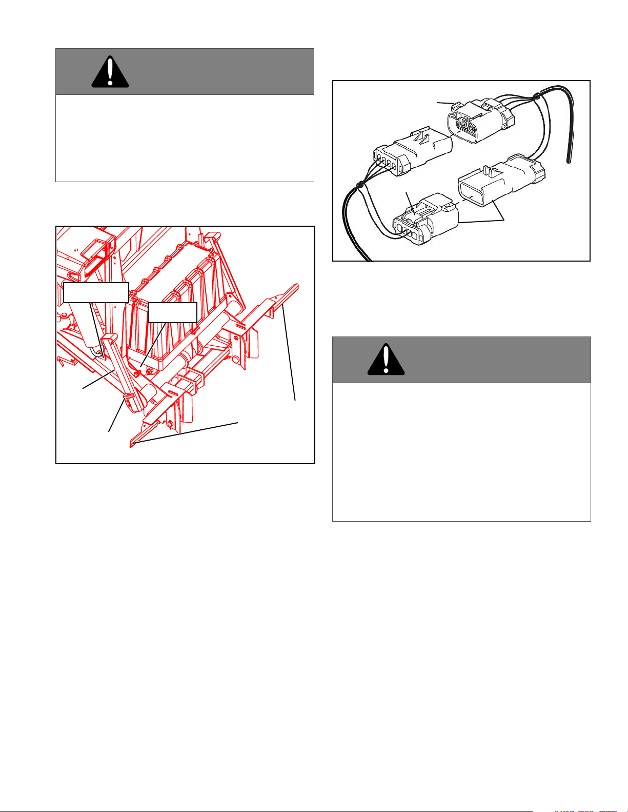
16. Apply included dielectric grease to all connectors.
NOTE: An adapter is recommended for vehicles with a
side post battery. (See Figure 1-3.) (Adapters can be pur-
chased from your Sno-Way dealer, Part #96100773.
Figure 1-3
Mechanical Installation
1. Remove the A-frame/tower assembly from the box.
2. Remove pump cover by pulling center rear of cover
off of tab, rotate forward and push off of front two tabs..
Attach lift link to light/lift bar, Install receiver using
instructions included with the controls package. Fill
reservoir on pump with supplied hydraulic fluid until the
oil level reaches the fill line. Do not overfill or oil may leak
from the breather.
3. Set a-frame/tower assembly lower hitch pins into
slots on truck subframe. (See Figure 1-4.)
Figure 1-4
4. Plug in power and control harness and rotate light/lift
bar into position. Lock in place by rotating cam handles.
Adjust A-frame/tower assembly level using plow control.
5. Once A-frame is level, turn off controller and
disconnect the power. (See "Mounting Snow Plow To
Vehicle" on page 10).
6. Position the drivers side (DS) and passenger side
(PS) wings in front of the A-frame/tower assembly. (See
Figure 1-5.)
Figure 1-5
WARNING
Failure to connect the main light harness on the
truck when plow is not attached will cause truck
lights to not operate, which could cause an
accident.
FAILURE TO FOLLOW CAN RESULT IN INJURY
OR DEATH.
ADAPTER
2’ RED
BATTERY CABLE
HITCH PINS
SUBFRAME
DS WING
A-FRAME/
TOWER
ASSEMBLY
PS WING

6
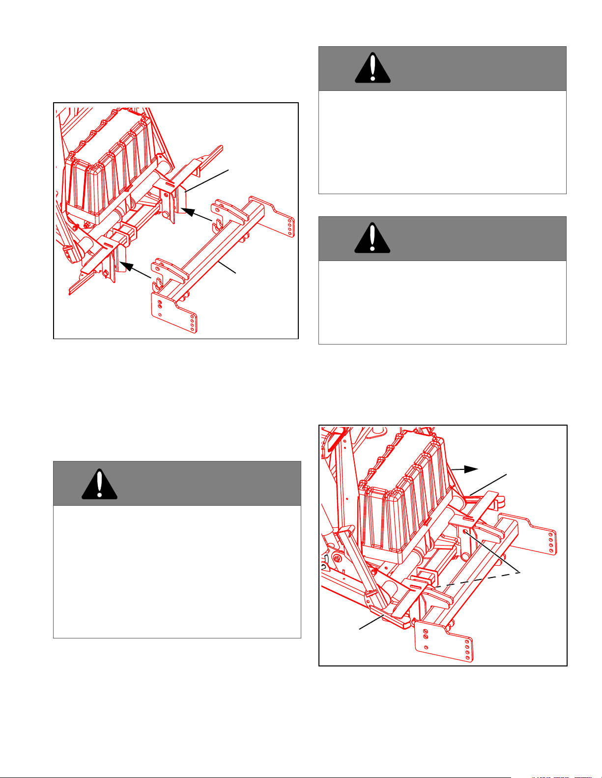
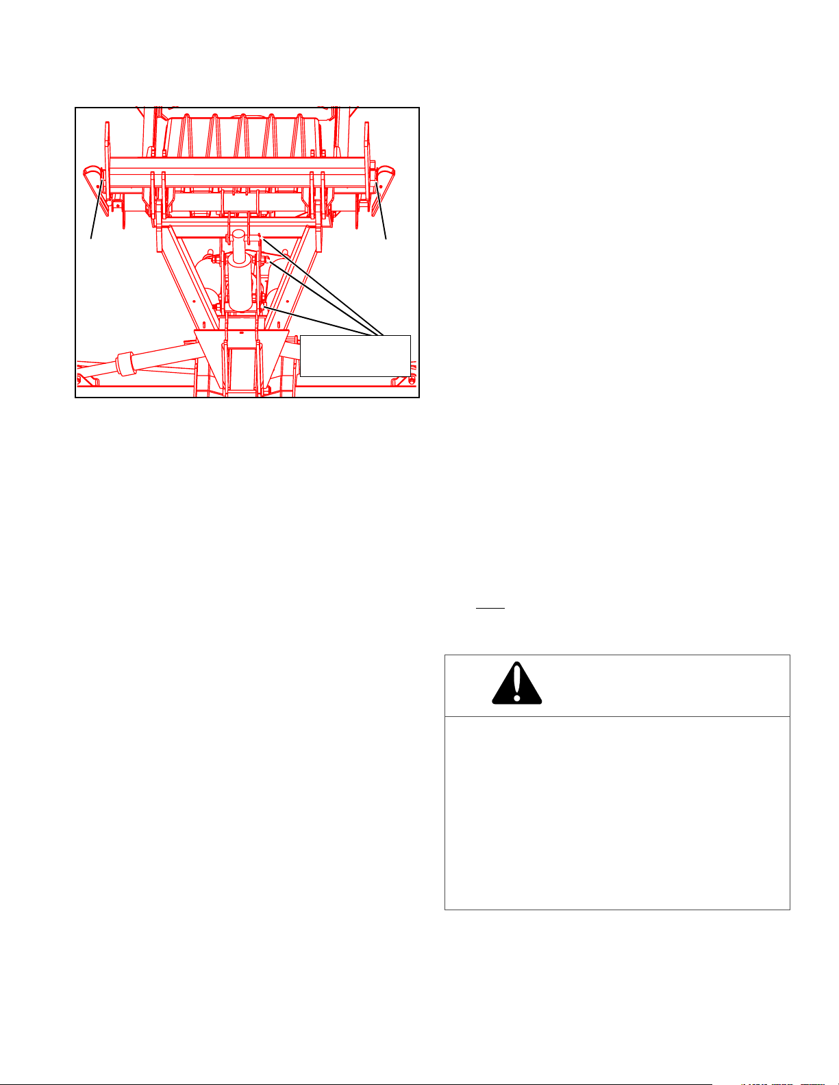
7. Coat main wing pivot pin with grease and insert
through the tower and wings. Leave top of pin
approximately 1" above the tower. (See Figure 1-6.)
Figure 1-6
8. Take deflector and place on tower with the tab on the
wing pivot pin going thru the rectangular hole of the
deflector. Align bolt holes in the wing pivot pin, deflector,
and tower. Push wing pivot pin down to the deflector and
tower. (See Figure 1-7.)
Figure 1-7
9. Secure the wing pivot pin to the tower assembly with
one 3/8" -18 x 1-1/4" cap screw and 3/8"-18
Locknut.(See Figure 1-7.)
10. Attach angle cylinder base to tower with a
5/8" x 2-7/8" clevis pin. Insert cotter pins into clevis pins. .
Attach angle cylinder rod to blade with a 1/2"-13 x 2-1/2"
cap screw and 1/2"-13 locknut. (See Figure 1-8.) Repeat
for opposite angle cylinder.
Figure 1-8
11. Attach a plow marker to each wing as shown and
secure using 5/16" x 1" cap screws and locknuts. (See
Figure 1-9.)
Figure 1-9
DS WING
WING
PIVOT PIN
PS WING
DEFLECTOR
3/8"-18
3/8-18 x 1-1/4"
CAP SCREW
LOCKNUT
1/2"-13
LOCKNUT
CAP SCREW
1/2"-13 X 2-1/2"
CLEVIS PIN
5/8" x 2-7/8"
COTTER PIN
ANGLE
CYLINDER
5/16" x 1"
CAP SCREWS
PLOW
MARKER
7
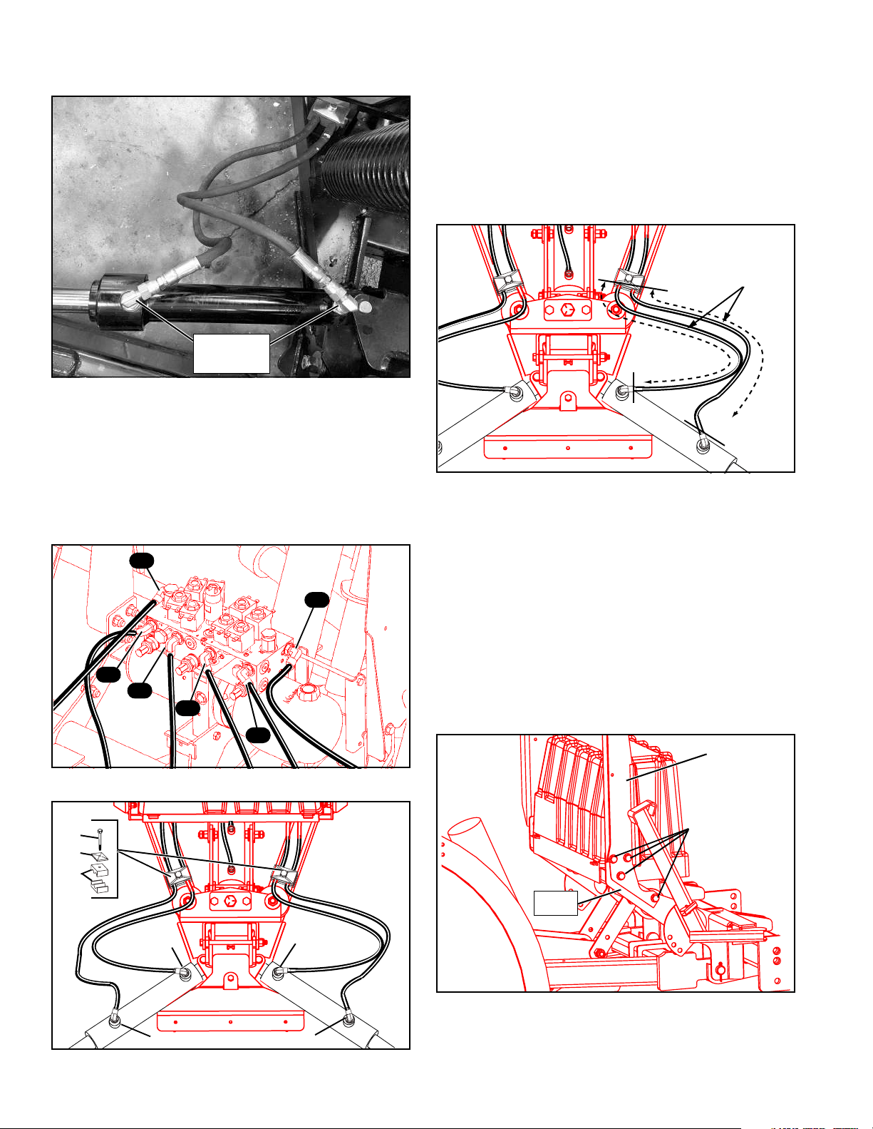
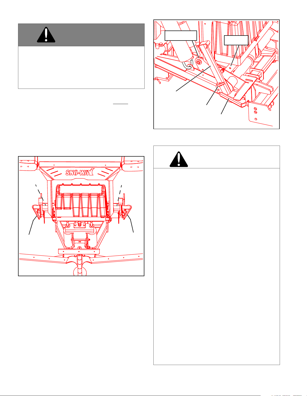
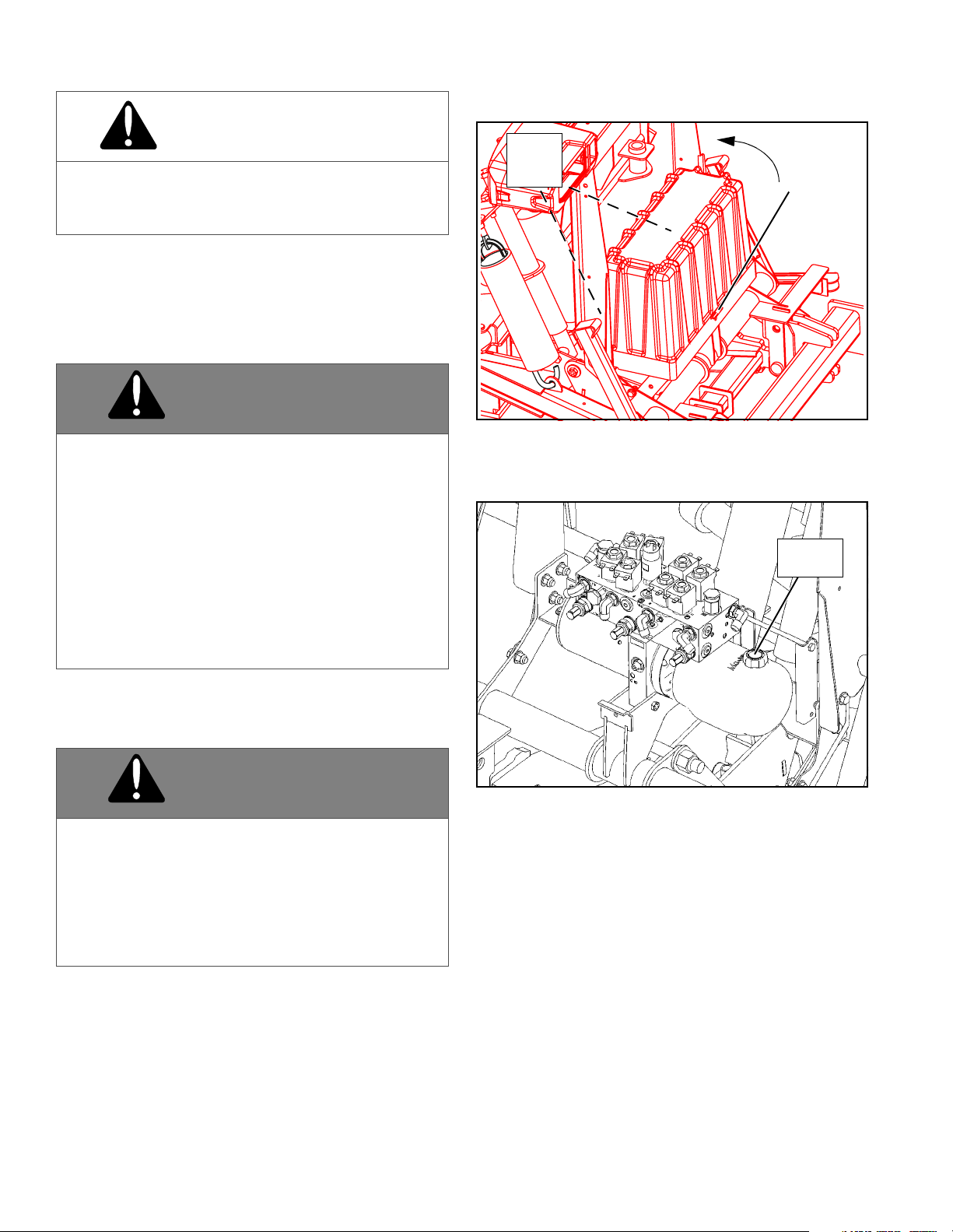
12. Install 90 deg. elbows into wing cylinder ports.
Orientate as shown in Figure 1-10.
Figure 1-10
13. Loosely connect hydraulic hoses to the wing
cylinders. (See Figure 1-10, Figure 1-11, and Figure 1-
12).
NOTE: C1 through C6 references are hydraulic ports on
the control valve that are marked accordingly. (See Fig-
ure 1-11 and Figure 1-12.)
Figure 1-11-View From Rear of Control Valve
Figure 1-12
14. Loosely position hydraulic hoses in hose clamps (A -
5/16" X 2" self-tapping screw, B - plate, C - clamp blocks)
on each side of the A-frame. (See Figure 1-12.)
15. Adjust each hose length from clamps to hose end
fittings to 26-1/2" and tighten both clamp screws. (See
Figure 1-13.)
NOTE: If installing screw with an impact wrench, ensure
that the wrench in adjusted to its lowest torque setting to
avoid fastener damage.
Figure 1-13
16. Orientate hydraulic hoses as shown in Figure 1-10.
NOTE: Hydraulic hoses must be installed as shown in
Figure 1-10 to avoid interference with the jackstand.
17. Tighten all hydraulic hose fittings securely.
18. Install pump cover by tillting pump cover forward,
sliding pump cover over front two tabs, rotate cover back,
and and pull center rear of cover over rear tab.
19. Remove left and right light support brackets from
power pack carton.
20. Position the DS light support bracket in position
against the lower light lift bar (LLLB). (See Figure 1-14.)
Figure 1-14
21. Install (4) 3/8" x 1.25" cap screws with (8) flat
washers and (4) locknuts from the provided parts into the
light support bracket holes, but do not tighten completely.
90 DEGREE
ELBOWS
C2
C1
C4
C3
C5
C6
A
B
C
C5
C6
C1
C2
26-1/2"
3/8" x 1.25"
CAP SCREWS,
FLAT WASHERS
& LOCKNUTS
DS LIGHT
SUPPORT
LLLB
BRACKET
8
22. Repeat steps 20 & 21 to install the passenger side
(PS) light support bracket to the LLLB.
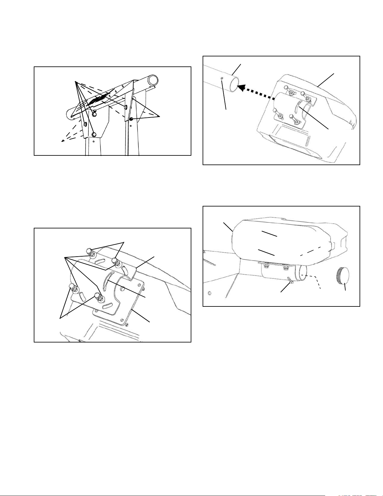
23. Secure light bar to supports with (6) 3/8" x 1" screws
and (6) lock nuts. Tighten cap screws to 45 lb-ft. (See
Figure 1-15.)
Figure 1-15
24. Align light bar supports to vertical position and tighten
(8) LLLB/light support brackets cap screws to 45 lb-ft.
(See Figure 1-14.)
25. Position a plow light clamp and rubber isolator on the
bottom of each plow light, aligning the corner slots in the
clamp with the four holes in the isolator and light
housings. (See Figure 1-16.)
Figure 1-16
NOTE: The large clamp slot must be facing toward the
turn signal side of each light.
26. Loosely install two 1/4" x 1" screws, with lock and flat
washers, through the front holes (lens side) of the light
clamp and isolator into each plow light housing.
IMPORTANT: If longer screws are installed in the
front holes, the reflective lens of the light will be
broken.
27. Loosely install two 1/4" x 1-1/4" screws, with lock
and flat washers, through the rear holes (back side) of
the light clamp and isolator into the light module housing.
28. Slide the plow lights onto the respective ends of the
light bar bracket, aligning the hole in the bottom of the
bracket with the slot in the plow light clamp. (See Figure
1-17.)
Figure 1-17
29. Install a 1/4" x 7/8" screw with 1/4" washer through
each clamp and light bar and loosely secure with a 1/4"-
20 nut. (See Figure 1-18.)
Figure 1-18
30. Apply dielectric grease to all light harness
connectors. Connect the plow light harness with the
black male connector to the driver side lamp and the
plow light harness with the black female connector to the
passenger side lamp.
31. Check operation of all lamp functions (Low beam
headlamp, high beam headlamp, marker lights and
directional signals).
32. Aim plow lights with plow in the fully raised position.
Lock the lamps in the adjusted position by tightening four
1/4" x 1" and 1/4" x 1-1/4" horizontal adjustment screws
and one 1/4" x 7/8" vertical adjustment screw and 1/4"
nut securely. (See Figure 1-17 and Figure 1-18.)
NOTE: In order to conform to Federal Motor Vehicle
Safety Standards a SAE J602 Approved aiming device
must be used to aim plow lights.
33. Install an end cap in each end of the light bar. (See
Figure 1-18.)
3/8" x 1"
3/8"
CAP SCREWS
LOCKNUTS
3/8"
LOCKNUTS
1/4" x 1-1/4"
SCREWS
PLOW LIGHT
CLAMP
1/4" x 1"
SCREWS
RUBBER
ISOLATOR
1/4" FLAT &
ON FOUR
SCREWS
LOCK WASHERS
LARGE
SLOT
CLAMP
PLOW LIGHT
BOTTOM LIGHT
PLOW LIGHT
ASSEMBLY
LIGHT BAR
BAR BRACKET
HOLE
CLAMP SLOT
DS PLOW
END
CAP
LIGHT SHOWN
1/4"-20
NUT
WITH 1/4" WASHER
1/4" x 7/8" SCREW

9
Blade Level Adjustment
The Sno-Way 26V has a Max AdjustTM feature that is set
when the plow is first installed and when initially run each
plowing season. The adjustment mechanism is designed
to make the plow wearstrip scrape evenly on flat surfaces
without leaving a trail of snow near the center or the edge
of the plow. Change in adjustment may be needed due
to wear conditions and when the plow is switched
between vehicles. Adjustments can be performed with a
few turns of a wrench.
Adjustment Procedure
1. Move vehicle to a level flat surface, such as a large
parking lot, or a garage floor.
IMPORTANT: If plow leveling procedure is being
performed on uneven pavement, the plow will be
difficult to level correctly. Also include all ballast
weight with the truck while adjusting the plow. Any
additional weight added to the truck after the plow is
adjusted may require the Max AdjustTM system to be
adjusted again.
2. Loosen jam nut on the tilt adjustment cap screw
located in the center section of the plow trip mechanism.
(See Figure 1-19.)
Figure 1-19
3. Swing wings to the straight position and lower plow to
the ground.
4. Turn Down Pressure ON.
5. Swing wings forward to the scoop position, with blade
on ground
6. If the center wear-strip begins to rise off of the floor,
stop moving the wings forward and turn the tilt
adjustment cap screw out. This will cause the tower to tilt
back and towards the truck.
7. Continue to move the wings forward (scoop position)
until they are free to move forward and backwards to the
straight position.
8. If the center wear-strip begins to rise off of the floor
when the wings are brought back to the V-Position, turn
the tilt adjustment cap screw in, causing the tower to tilt
forward.
9. Once proper adjustment has been attained, tighten
the jam nut on the tilt adjustment cap screw.
IMPORTANT: Adjusting in Down-Pressure is
different than adjusting in Float. If the plow is leveled
while in Down-Pressure (which is what is explained
in the manual here) the wings will tend to be "off the
ground" in scoop, when the Down-Pressure is turned
Off. Be aware of which level you are plowing the
most in, Down-Pressure-Level, or Float-Level.
NOTE: If you set the Plow-Level when in float, the outer
wing edge of the wear strip will wear first when down
pressure is turned on.
PLOW
MARKER
TILT ADJUSTMENT
CAP SCREW
JAM NUT
10
Mounting Snow Plow To Vehicle
1. Drive truck into plow, aligning light/lift bar frame with
subframe lugs. Pins should fit inside slots cut into
subframe lugs. (See Figure 1-20.)
Figure 1-20
NOTE: If pins are too high or low to fit into slots on sub-
frame, adjust the plow height after power is connected in
the next step. Plug hand held controller into the plow con-
trol harness if controller is wired. To lower the pins, turn
on down pressure and press down. To raise the pins,
press up.
2. Connect the plow and truck power harness
connectors together.
3. Remove controller from truck cab (and plug into plow
control harness if control is wired).
4. Rotate light/lift bar into position by turning on down
pressure and pressing the lower button. (See Figure 1-
21.)
Figure 1-21
5. Rotate mount handles in to lock pins in place. Put
plow into float position by turning down pressure off. (See
Figure 1-21 and Figure 1-22).
WARNING
The power cable in front of the truck is wired
directly to the battery. The power cable is
always energized, even if the truck is turned off.
Always replace the protective cap after
disconnecting the plow power cable. Allowing
an unprotected plug to contact metal parts of
the truck may cause electrical component
damage. Never use a metal object to clean the
plug contacts.
FAILURE TO FOLLOW CAN RESULT IN INJURY
OR DEATH
LIGHT / LIFT
BAR FRAME
SUBFRAME
ON TRUCK
MOUNTED
WARNING
When using the hand held controller to raise or
lower the plow A-frame for mounting the plow
to the vehicle, be especially careful of the
movement of the light bar. This movement will
occur when raising or lowering the A-frame or
jack stand.
FAILURE TO FOLLOW CAN RESULT IN INJURY
OR DEATH
WARNING
Pressing the blade angle functions will result in
the A-frame swinging if it is not secured to the
truck. Do not press the angle function during
plow installation.
FAILURE TO FOLLOW CAN RESULT IN INJURY
OR DEATH
ROTATE
LIGHT/LIFT
BAR
UPPER
INTO SLOT
WILL DROP
HITCH PINS
MOUNT
HANDLE
MOUNT
HANDLE
11
NOTE: Upper hitch pins are fully engaged when mount
handle is tight against pin bracket and you cannot see
the upper hitch pin between the pin bracket and mount
handle.
If upper hitch pins are not fully engaged:
A. Raise plow an inch off the ground, then lower. Or,
B. Turn Down Pressure ON and then OFF.
Upper hitch pins will snap into place. (See Figure 1-21
and Figure 1-22).
Figure 1-22
6. Unplug wired control from plow.
7. Disengage jack stand pin by pulling on pin handle.
Rotate the jack stand to the raised position. Engage the
pin by pushing on the handle. Make sure pin is engaged
in hole by rotating jack stand back and forth. (See Figure
1-23.)
Figure 1-23
WARNING
Make sure that upper hitch pins are engaged
before moving truck. Hitch pins not fully
engaged could result in the plow separating
from the truck.
FAILURE TO FOLLOW CAN RESULT IN INJURY
OR DEATH
UPPER
HITCH PIN
UPPER
HITCH PIN
MOUNT
HANDLE
IN
MOUNT
HANDLE
IN
CAUTION
Many new vehicles are equipped with onboard
circuit sensors designed to display a
dashboard LED when a headlight fails.
Generally, these sensors are activated or
tripped any time the circuit is being called upon
to function while the headlight circuit is
incomplete. This means that if a headlight fails
while the headlight is in operation, the sensor
will trip and the dashboard indicator will light
up. It also means that if a headlamp socket is
left empty—or a faulty lamp is installed—and
the circuit is then activated, the sensor will trip
and the dashboard indicator will light up.
These headlight circuit sensors are often
engineered with pre-designated failure limits.
This means that a sensor may be tripped a
limited number of times. After that limit is
reached the sensor may need to be reset by the
dealer or replaced by the manufacturer.
Sno-Way EIS plow light systems essentially
operate through a planned interruption of the
headlight circuit. When the truck-side
connectors are detached from one another, the
vehicle headlamps are disconnected from the
truck circuits which otherwise power them.
Until those truck-side connectors are attached
to the plow-side light connectors, the truck-
side circuits are open. This means that if the
truck’s onboard sensors are active while the
plow lights are being attached to the truck, the
truck’s sensors may trip.
MOUNT
JACK
PIN
HANDLE
STAND
BELL CRANK
LIFT LINK
HANDLE
12
8. Unplug light harness connectors on truck, and light
connectors on plow, which had been plugged together for
corrosion protection during storage. (See Figure 1-24.)
Figure 1-24
9. Plug plow light connectors into mating connectors on
truck light harness. (See Figure 1-25.)
Figure 1-25
10. If control is wired, plug control inside truck cab and
control harness on plow into truck.
11. Raise, lower and angle plow to make sure no hoses
or wires pinch in the plow mechanism.
CAUTION
To avoid unnecessarily tripping the truck’s
sensor, every time the plow lights are being
attached to the truck circuits or the truck
circuits are being reattached to the vehicle
lights, the truck’s lights should be turned off.
Due to the aforementioned concerns, operators
of vehicles equipped with EIS lights should
make themselves aware of whatever circuit
sensors may be installed on their vehicles.
Operators should further become familiar with
their vehicle manufacturer’s description of how
their truck’s sensors are actuated or tripped.
Finally operators should know whether
predesignated failure limits may be engineered
into their truck’s sensors and what repair or
replacement procedures are recommended
should those limits be reached. Currently, the
vehicle models affected are as follows:
2006 and later-Dodge Dakota and Durango - All
packages.
2006 and later-Dodge 1500, 2500 and 3500- All
packages.
2008 Ford F250-F550 - All packages.
PLOW LIGHT
CONNECTORS
TRUCK LIGHT HARNESS
CONNECTORS
WARNING
Failure to properly connect plow lights to
vehicle light harness will prevent plow lights
from functioning. Follow proper procedure to
connect light harnesses and test lights before
operating.
FAILURE TO FOLLOW CAN RESULT IN INJURY
OR DEATH
PLOW CONTROL HARNESS
PLOW LIGHTS
CONNECTED TO TRUCK
LIGHT HARNESS
13
Installing The Cylinder Lock Clamp
1. Raise the plow to the full UP position.
2. Turn the ignition OFF and apply the parking brake.
3. Turn OFF the hand-held controller.
4. Remove the pin from the cylinder lock clamp.
5. Position the cylinder lock clamp around the exposed
(chrome) portion of the lift cylinder with the open side of
the cylinder lock up. Install the pin. (See Figure 1-26.)
Figure 1-26
6. Lower the plow so that cylinder lock clamp is tight
against cylinder.
Removing Snow Plow From Vehicle
Choose a location for the plow storage, which will allow
the plow to be removed from the vehicle and not be
moved after removal. Also, choose a location that will not
allow the plow stand to sink into the ground. A dry,
protected area is recommended.
1. Lower plow to the ground, put vehicle in park, turn off
the engine and set the parking brake.
2. Disconnect the plow light connectors from the truck
harness connectors. (See Figure 1-27.)
Figure 1-27
3. To prevent corrosion on the contacts, plug the male
and female connectors on the plow light harness
together. (See Figure 1-28.)
Figure 1-28
4. To make the truck lights operable, plug the male and
female connectors on the truck light harness together.
(See Figure 1-28.)
WARNING
Always install the cylinder lock clamp when the
plow blade is raised and the operator is not
engaged in plowing operations. Equipment
failure or inadvertent operation of the plow
control while driving could allow the plow blade
to fall, resulting in injury.
FAILURE TO FOLLOW CAN RESULT IN INJURY
OR DEATH
WARNING
Failure to lower plow onto clamp could block
headlights resulting in an accident.
FAILURE TO FOLLOW CAN RESULT IN INJURY
OR DEATH
WIRE LOCK PIN
LIFT
LINK
A-FRAME BOTTOM
BELL
CRANK
CYLINDER
LOCK
CLAMP
CYLINDER
ROD
CONNECTORS FROM
DISCONNECT PLOW LIGHT
TRUCK LIGHT HARNESS
PLOW LIGHT
CONNECTORS
TRUCK LIGHT HARNESS
CONNECTORS
14
5. Disengage jack stand pin by pulling on the pin
handle. (See Figure 1-29.)
Figure 1-29
6. Rotate the jack stand into the lowered position.
Engage the pin handle by pushing on the handle. Make
sure pin is engaged in hole by rotating jack stand back
and forth. (See Figure 1-29.)
7. Remove controller from truck cab (and plug into plow
control harness if control is wired).
8. Turn Down Pressure ON and then OFF.
9. Rotate mount handles out to unlock main pins. (See
Figure 1-29.)
10. Raise A-frame by pressing the controller UP button.
11. Disconnect the plow control harness connectors and
replace the protective storage caps to prevent corrosion
on the contacts. (See Figure 1-30.)
Figure 1-30
12. Disconnect the plow power harness connectors and
replace the protective storage caps to prevent corrosion
on the contacts.
13. Back truck away from plow.
WARNING
Failure to reconnect the main light harness on
the truck when removing plow will cause truck
lights to not operate, which could cause an
accident. Test lights before operating.
FAILURE TO FOLLOW CAN RESULT IN INJURY
OR DEATH
MOUNT HANDLE
STRAIGHT OUT
JACK
STAND
PIN
HANDLE
BELL CRANK
LIFT LINK
WARNING
The power cable in front of the truck is wired
directly to the battery. The power cable is
always energized, even if the truck is turned off.
Always replace the protective cap after
disconnecting the plow power cable. Allowing
an unprotected plug to contact metal parts of
the truck may cause electrical component
damage. Never use a metal object to clean the
plug contacts.
FAILURE TO FOLLOW CAN RESULT IN INJURY
OR DEATH
LOCKING TAB
SECONDARY LOCK
STORAGE
CAPS

15
General
• Before operating, perform a thorough visual
inspection of the equipment. Look for fluid leaks,
cracked, bent or broken components, loose nuts,
bolts or attachments and proper fluid levels.
• A clean hydraulic system is essential to long pump
life and proper performance.
• When adding oil to the reservoir, wipe the area
around the filler port clean before removing the
breather cap. Use clean oil and a clean funnel, (DO
NOT use a cloth or rag to strain the oil).
IMPORTANT: Sno-Way supplies type 5606 Sno-Way
Hydraulic Oil with the unit from the factory. If
additional oil is added it must be compatible with
Sno-Way oil. If another type of oil has been used in
the system the same type of oil must be used for
topping off system. Improper hydraulic fluid can
cause operating problems in cold weather.
• Do NOT use synthetic oil.
• Oil must contain an anti-foam additive.
• The operational environment for snow plows is an
extremely harsh and corrosive one.
• Ensure all electrical connections are clean and
tight.
• To prevent rust from forming, clean and repaint
exposed metal surfaces.
• NEVER operate the equipment with the protective
covers or guards removed.
Periodic Inspection
After approximately every 20 hours of operation perform
the following inspections procedures:
1. Inspect the plow assembly including the sub-frame
assembly for any damage or excessive wear. Replace
parts as necessary.
2. Inspect all fasteners (Plow & Truck Mount) to ensure
they are properly tightened. Re-tighten loose fasteners to
the proper torque. Loose fasteners on the Bellcrank,
Power Unit to the Pump Platform and Truck Mount must
have the nylock nuts replaced and tightened while using
Sno-Way thread locker 96115529. (Refer to torque
specification chart in this manual).
3. Apply oil or grease to the wing pivot pin between the
hinge tubes and plates. (See Figure 1-31.)
Figure 1-31
4. Apply a small amount of light oil to the wing cylinder
pivot pins and to pivot pins between the blade assembly,
A-Frame, and spring brackets. (See Figure 1-32.)
Figure 1-32
WARNING
Before servicing plow, lower plow to ground
and disconnect main power harness.
FAILURE TO HEED CAN RESULT IN INJURY
OR DEATH.
WING PIVOT
LUBRICATION
POINTS
PIVOT
PINS
DS WING
PIVOTS
CYLINDER
PS WING
PIVOTS
CYLINDER
PIVOT
PIN
MAINTENANCE
16
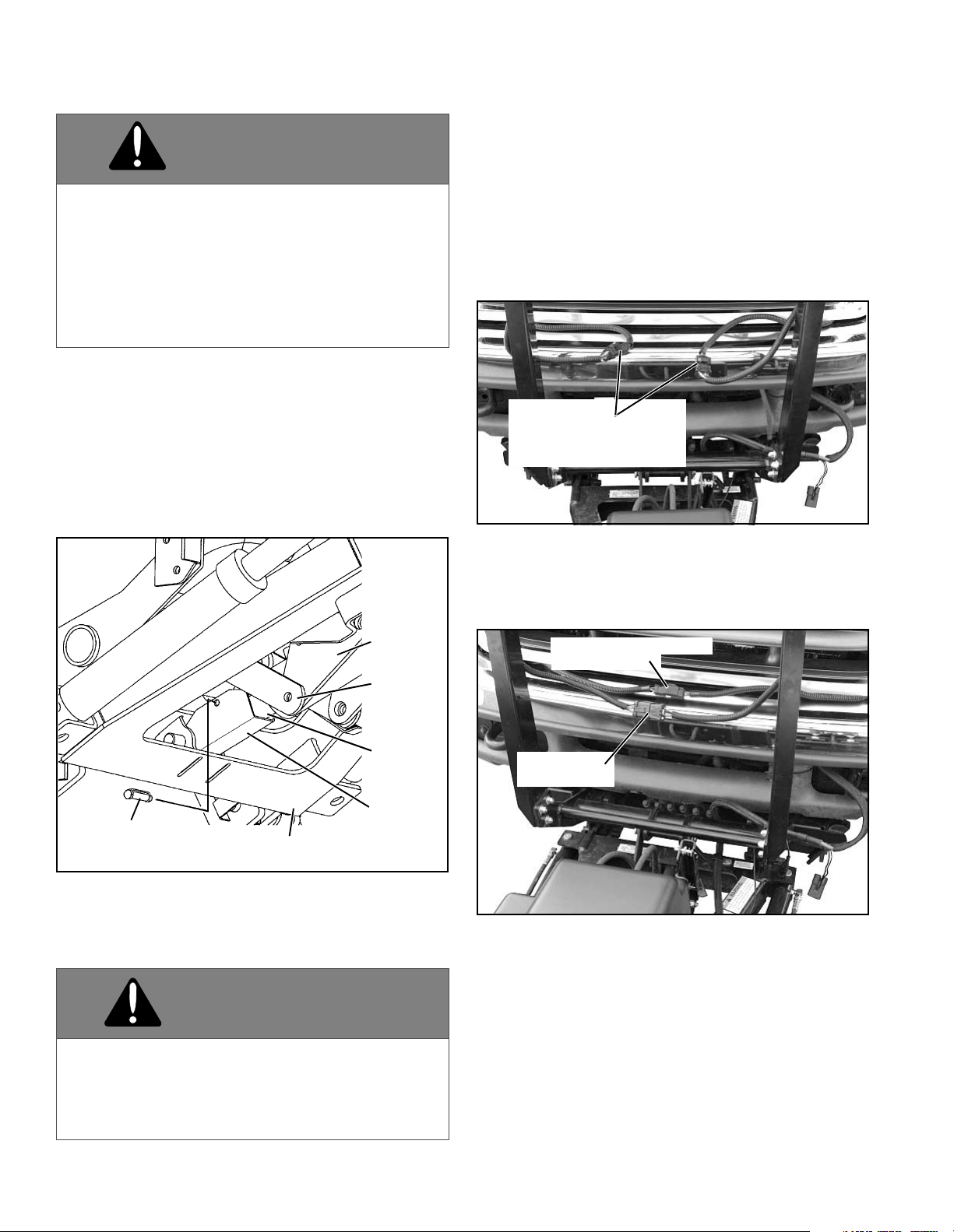
5. Apply a small amount of light oil to the lift cylinder
assembly pivot pins and both attach lock pins. (See
Figure 1-33 - View From Bottom.)
Figure 1-33 - View From Bottom
Special Fasteners Torques and Require-
ments
IMPORTANT: Incorrectly securing fasteners may
result in incorrect operation, excessive wear, and
early failure of plow components. It may also void
your warranty.
• ALWAYS check to make sure you are using the
correct torque specification for the fastener you are
using.
• DO NOT use any lubricants on the threads of any
fastener unless specifically called for in the
assembly or maintenance story for that component.
• NEVER use liquid locking materials, such as
Locktite™ or Threadmaker™, on any fasteners
unless specifically called for in an assembly or
maintenance story for that component.
Standard Fasteners:
The Torque Specifications Chart on page 34 of this
manual should be used as the guide for fastener torque
requirements for most standard fasteners used on the
plow.
Standard fasteners with special torque requirements will
be noted in assembly or service stories pertaining to the
specific piece of equipment.
Hydraulic Fittings
Hydraulic fittings with lock nuts should be assembled with
at least three full turns of the fitting in the port and then the
lock nut should be tightened to 27 lb-ft.
Hydraulic fittings with 37 degree flare end swivels should
be torqued to 18-20 lb-ft.
Hydraulic Cylinders
To avoid corrosion during storage, coat the exposed
(chrome) portion of the lift and angle cylinders with a light
grease.
Electrical Quick Disconnect Plugs
This plow is equipped with the EIS® (Energy Interruption
SystemTM). Any time the plow is removed from the
vehicle, plug the electrical lighting quick disconnect ends
together to prevent corrosion from forming on terminal
ends.
Fluid Requirements
IMPORTANT: Sno-Way supplies type 5606 Sno-Way
Hydraulic Oil with the unit from the factory. If
additional oil is added it must be compatible with
Sno-Way oil.
It is recommended that the fluid in the hydraulic system be
changed once a season.
Do NOT use synthetic oil.
Oil must contain an anti-foam additive.
•
ATTACH
LOCK PIN
ATTACH
LOCK PIN
LIFT CYLINDER
ASSEMBLY PIVOT
PINS
CAUTION
• Using the proper oil increases the life
expectancy of the most critical part of your
plow; the Hydraulic power unit.
• Failure to use the proper oil can cause
extensive damage to the power unit, seals and
hydraulic rams.
• Improper oil can cause operating problems and
poor performance in cold weather.
17
Changing Oil and Cleaning Filter Screen
NOTE: Oil should be changed at the beginning of every
season. We recommend cleaning the filter screen at
every oil change, this will help ensure maximum life and
maximum performance from the pump assembly.
1. Lower plow assembly to ground, put vehicle in park
and turn off engine. Turn hand-held controller off.
2. To prevent inadvertent short circuit or electrical
shock, disconnect the power harness and control
harness at the vehicle bumper.
3. Remove pump cover by pulling center rear of cover
off of tab, rotate forward and push off of front two tabs..
(See Figure 1-34.)
Figure 1-34
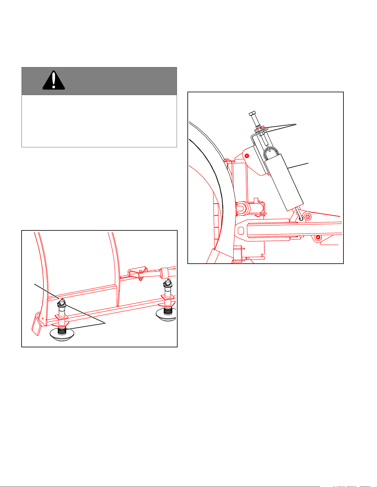
4. Remove the filler/breather cap from the reservoir.
(See Figure 1-35.)
Figure 1-35
5. Using an oil suction gun or similar tool, remove the oil
from the oil reservoir.
NOTE: Be careful to avoid contacting and damaging the
filter screen while removing the oil.
6. Remove the lift cylinder hose(s) from the valve block.
Remove the wing cylinder hoses from the fitting in the
valve block. Mark hoses before removal to be certain
they are reinstalled in the correct location.
7. Place the hoses in a container to catch oil expelled
from cylinders. Cycle the lift cylinder by disconnecting
hitch pins and pushing and pulling on light bar. Cycle
wing cylinders by disconnecting from wing and pushing
and pulling on cylinder rod.
CAUTION
Using the proper oil increases the life
expectancy of the most critical part of your
unit; the Hydraulic power unit.
WARNING
• Allow the system to cool down before draining
oil or handling system components. Serious
burns can result from contact with hot oil.
• Never disconnect any hydraulic line or fitting
with the unit in the raised position. Always
lower the unit and relieve pressure before
removing any lines or caps.
FAILURE TO HEED CAN RESULT IN INJURY
OR DEATH.
WARNING
Ensure engine is OFF and set parking brake
before working on plow. Vehicle movement,
equipment failure or inadvertent operation of
the control switches during maintenance could
result in serious injury
FAILURE TO HEED CAN RESULT IN INJURY
OR DEATH.
REAR
TAB
TWO
FRONT
TABS
FILLER
CAP

18
8. Loosen the clamp securing the oil reservoir to the
pump assembly and remove the oil reservoir being
careful not to damage the filter screen while removing the
oil reservoir. (See Figure 1-36.)
Figure 1-36
9. Pull the filter screens off the return and suction tubes
(hold it by the metal cover, not by the screen) and clean
with a suitable solvent. Blow dry with low pressure
compressed air from the inside.
10. Carefully reinstall the filter screens.
11. Visually check that the pickup tube and filter face
down. (See Figure 1-36.) If not, rotate the pickup tube
until the tube and filter face down.
12. Clean the oil reservoir inside and out with a suitable
solvent.
13. Inspect the O-ring seal for damage, replace if
needed, lubricate with fresh oil and reinstall reservoir
carefully to avoid damaging the O-ring.
14. Reconnect hydraulic fittings and hoses in their
correct position and torque to 20-25 lb-ft. If unit utilizes O-
ring and jam nut type connectors tighten jam nut to 15-20
lb-ft.
15. Fill the hydraulic oil reservoir until the fluid level
registers full on oil level mark on oil reservoir.
NOTE: Vehicle must be parked on level ground, Plow
must be in the lowered position, and Wings must be
folded rearward ("V") in order to properly check the oil
level. Checking oil level with plow elevated or with wings
straight or folded forward will give wrong reading.
16. Refer to plow operation instructions and operate the
plow to purge all air from the hydraulic system.
17. Replenish the fluid in the reservoir until the fluid level
registers full on oil level mark on oil reservoir.
18. Operate system and check for leaks, repair or tighten
as necessary.
19. Install the pump cover.
Cutting Edge Replacement
NOTE: Cutting edge must be replaced when it is worn to
the bottom edge of the frame.
1. Raise plow to full up position.
2. Place a jack stand under both ends of the blade
bottom rail.
With the Down PressureTM Hydraulic System OFF, lower
plow until firmly resting on jack stands
3. With an assistant, remove hardware and worn
wearstrip from plow.
4. Insert one carriage bolt through cutting edge and
blade on either end of the plow and loosely install one
lock nut.
5. Insert one carriage bolt through the opposite end of
the cutting edge and blade on the opposite end of the
plow and loosely install one lock nut.
6. Insert the remaining carriage bolts and loosely install
lock nuts on each.
7. Beginning on either side, tighten all nuts securely.
CAUTION
Do Not use Teflon® tape or pipe compound on
hydraulic fittings. These can dislodge and jam
valves in the hydraulic system.
RETURN TUBE
PICK-UP TUBE
FILTER SCREENS WARNING
The bottom of the cutting edge can be very
sharp. Whenever handling a cutting edge, work
with an assistant and wear suitable protective
gloves to avoid serious injury.
FAILURE TO HEED CAN RESULT IN INJURY
OR DEATH.
19
Plow Shoe Adjustment
This plow is equipped with the ability to utilize four (4) plow
shoes. Two plow shoes are located at the outboard end of
each wing, and two plow shoes are located on the inboard
section of each wing, close to the center tower.
Adjust the plow shoes as follows:
1. Raise plow to full up position.
2. Support blade with a jack.
3. Turn vehicle ignition switch and plow control OFF and
apply emergency brake.
4. Adjust shoe assemblies by removing shoe mounting
lynch pin and adding or subtracting washers on the top or
bottom of the shoe-mounting bracket. (See Figure 1-37.)
Figure 1-37
5. After the disk shoe position is properly adjusted place
remaining washer on the shoe stem - above the disk
shoe mounting bracket and below the retaining lynch pin
- to remove all up and down movement of the disk shoe
in the bracket. Failure to do so will result in excessive
wear of the holes in mounting bracket or bending of the
disk shoe stem.
IMPORTANT: Snap lynch pin ring over so that it
contacts the pin. If ring does not contact lynch pin,
rotate the pin and reverse the direction of the ring. If
the ring does not contact the pin it is not locked and
could fall out.
Trip Spring Adjustment
Check the plow shoe adjustment as follows:
1. Level the tower and wings. (See "Blade Level
Adjustment" on page 9).
2. Check gap on springs with a feeler gauge. The gap
between two or more coils should be .015" (A 3x5
postcard is approximately .015" thick). (See Figure 1-38.)
Figure 1-38
If the gap needs adjustment:
a. Loosen the bottom nut on the spring eye bolt(s).
b. Tighten or loosen the top nut until the correct
tension is reached, by measuring with a feeler
gauge.
c. Tighten the bottom nut(s) on all spring eye bolts.
WARNING
Keep hands and feet clear of wings and center
section when setting blocking and lowering
plow. Moving or falling assemblies could result
in serious injury.
FAILURE TO HEED CAN RESULT IN INJURY
OR DEATH.
PIN
WASHERS
0.015" GAP
MAXIMUM
ADJUSTMENT
NUTS
Table of contents
Other Sno-Way Snow Blower manuals


