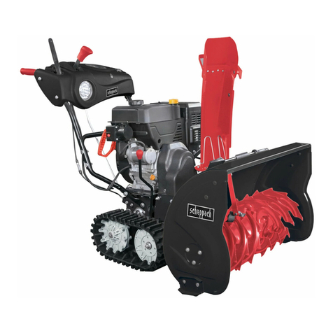
Sno-Way SWS 30 Operating instructions

97101997A
INSTALLATION &
OWNERS MANUAL
SWS 30
ON/OFF CONTROL
99101253
©2016 Sno-Way®International

1
TABLE OF CONTENTS
Page
INTRODUCTION ......................................................................................................... 2
SAFETY ...................................................................................................................... 3
INSTALLATION ........................................................................................................... 4
Introduction ....................................................................................................... 4
Tool List ............................................................................................................. 4
Installation ......................................................................................................... 4
OPERATION................................................................................................................ 6
Theory of Operation ......................................................................................... 6
On/Off Motor Controller Operation.................................................................. 6
Wiring Harnesses ............................................................................................. 6

2
This manual was written for the assembly, installation and
maintenance of your new SNO-WAY®SWS 30.
Most importantly, this manual provides an operating plan
for safe use. Refer to the Table of Contents for an outline
of this manual.
Please keep this manual with your machine at all times as
reference material and so it can be passed on to the next
owner if the machine is sold.
We require that you read and understand the contents of
this manual COMPLETELY, especially the chapter on
SAFETY, before attempting any procedure contained in
this manual.
The Society of Automotive Engineers has adopted
this SAFETY ALERT SYMBOL to pinpoint character-
istics that, if NOT carefully followed, can create a
safety hazard. When you see this symbol in this man-
ual or on the machine itself, BE ALERT!, your per-
sonal safety and the safety of others, is involved.
• Defined below are the SAFETY ALERT messages
and how they will appear in this manual.
BE AWARE! It is illegal to remove, deface or other-
wise alter the safety decals mounted on this equip-
ment.
We reserve the right to make changes or improve the
design or construction of any part(s) without incurring the
obligation to install such parts or make any changes on
any unit previously delivered.
Graphics and illustrations may be used which may show
equipment and/or options not included in every
installation without incurring the obligation to install such
parts or make changes on units previously delivered.
Sno-Way Service Parts Manuals are available on-line or
at your authorized Sno-Way dealer. Request part number
97101915 for the SWS 30 Controllers.
Factory contact information is available at
www.snoway.com.
WARNING
FAILURE TO FOLLOW CAN RESULT IN DEATH
OR INJURY.
CAUTION
Information, that if not carefully followed, can
cause injury or damage to equipment!
INTRODUCTION
DEALER
NAME
PHONE ( )–
ADDRESS
CITY STATE ZIP
(FILL IN)
ORIGINAL PURCHASER
NAME
PHONE ( )–
ADDRESS
CITY STATE ZIP
(FILL IN)

3
SAFETY
BEFORE ATTEMPTING ANY PROCEDURE IN THIS
BOOK, READ AND UNDERSTAND ALL THE SAFETY
INFORMATION CONTAINED IN THIS SECTION. IN
ADDITION, ENSURE ALL INDIVIDUALS WORKING
WITH YOU ARE ALSO FAMILIAR WITH THESE
SAFETY PRECAUTIONS.
For your safety Warning and Information Decals have
been placed on this product to remind the operator
to take safety precautions. It is important that these
decals are in place and are legible before operation
begins. New decals can be obtained from Sno-Way or
your local dealer.
REMEMBER The careful operator is the best
operator. Most accidents are caused by human error.
Certain precautions must be observed to prevent the
possibility of injury to operator or bystanders and/or
damage to equipment.
NEVER exceed vehicle GVWR, GAWR or Vehicle Hitch
Tongue Weight Rating.
NEVER operate spreader when under the influence of
alcohol, drugs or other medications that could hamper
your judgement and reactions. An accident may result in
serious injury or death to other persons or yourself.
ALWAYS operate vehicle in a well-ventilated area. The
carbon monoxide in exhaust gas is highly toxic and can
cause serious injury or death.
NEVER allow hands, hair or clothing to get near any
moving parts such as fan blades, belts and pulleys. Never
wear neckties or loose clothing when working on the
vehicle or Spreader.
NEVER wear wrist watches, rings or other jewelry when
working on the vehicle or individual equipment. These
things can catch on moving parts or cause an electrical
short circuit that could result in serious personal injury.
ALWAYS wear safety goggles when working on the
vehicle to protect your eyes from battery acid, gasoline,
and dust or dirt from flying off of moving engine parts.
ALWAYS be aware of and avoid contact with hot
surfaces such as engine, radiator, and hoses.
ALWAYS wear safety glasses with side shields when
striking metal against metal! In addition, it is
recommended that a softer (non-chipable) metal material
be used to cushion the blow. Failure to heed could result
in serious injury to the eye(s) or other parts of the body.
NEVER allow children or unauthorized person to
operate this spreader.
NEVER exceed 45 m.p.h. when loaded spreader is
attached to vehicle. Braking distances may be increased
and handling characteristics may be impaired at speeds
above 45 m.p.h. It is strongly recommended to load the
spreader at the job site and to dispense all of the
materials at the job site. Transportation of a loaded
spreader causes the material to become impacted and
may cause spreader flow problems.
ALWAYS lock the vehicle when unattended to prevent
unauthorized operation.
ALWAYS check the job site for terrain hazards,
obstructions and people.
ALWAYS check surrounding area for hazardous
obstacles before operating this unit.
ALWAYS inspect the unit periodically for defects. Parts
that are broken, missing or plainly worn must be replaced
immediately. The unit, or any part of it should not be
altered without prior written approval of the manufacturer.
ALWAYS shut off the vehicle engine, place the
transmission in Park, turn the ignition switch to the “OFF”
position and firmly apply the parking brake of the vehicle
before attaching or detaching the spreader from the
vehicle or when making adjustments to the spreader
gates and/or deflectors.
ALWAYS make sure personnel are clear of area being
spread. Material is discharged from spreader at a high
rate of speed and could injure bystanders.
ALWAYS inspect bolts and pins whenever attaching or
detaching the spreader, and before traveling. Worn or
damaged components could result in the spreader
dropping to the pavement while driving, causing an
accident.
NEVER place fingers in mounting frame or mount lug
holes to check alignment when attaching spreader.
Sudden motion of the spreader frame could severely
injure a finger.
NEVER use material in the spreader containing twigs,
brush, plastics, cans or other trash. Foreign materials
could plug drive and discharge and damage unit.
NEVER use wet materials in the spreader. This unit is
not designed to handle wet materials. Use only dry free
flowing materials.
NEVER leave materials in hopper for long periods of
time. Remember salt is hygroscopic and will attract
enough atmospheric moisture to cause it to "cake".
NEVER work on the vehicle without having a fully
serviced fire extinguisher available. A 5 lb or larger CO2
or dry chemical unit specified for gasoline, chemical or
electrical fires, is recommended.
NEVER smoke while working on the vehicle. Gasoline
and battery acid vapors are extremely flammable and
explosive.
NEVER free up a jam or unclog spreader while it is
plugged in. Always turn off vehicle and unplug spreader
when working on it.
NEVER remove a spreader full of material, or even
partially filled with material, from the vehicle. Always
empty spreader prior to removal from the vehicle.
REMEMBER it is the owner’s responsibility for
communicating information on the safe use and
proper maintenance of this machine.

4
Introduction
The information contained in this section will instruct you
on the proper installation and set up of the controller and
wire harness.
REMEMBER After the SWS 30 is installed on the
vehicle, the Pre-Delivery Check List and Delivery
Check List must be completed.
Tool List
Installation
Figure 1-1
1. Locate the following parts:
• Vehicle Power Harness
• Battery Power Harness
• Toggle Switch
• Female Terminal (2)
• 3/8" Ring Terminal
• Cable Ties
• 20A Fuse
2. Disconnect the NEG. (-) battery cable from the
battery.
NOTE: Take the extra time needed to plan the routing of
the wiring harness before drilling any holes or fastening
the harness or toggle switch in place. Read all the
instructions carefully to ensure all the required conditions
are met for a safe and professional installation.
Figure 1-2
3. Uncoil the Battery Power Harness and attach it to the
Positive (+) terminal on the battery.
4. Look for an existing hole in the vehicle firewall. The
hole must be 3/8" or larger.
Safety Goggles
Wire Crimp Tool
Utility Knife
Drill
Drill Bit, 3/8"
20A Fuse
Toggle
Switch
Cable
Tie
Vehicle Power
Harness
Battery Power
Harness
Female
Terminal
3/8" Ring
Terminal
WARNING
Disconnect the vehicle NEG. (-) battery cable
while performing Steps 2 - 13 to avoid serious
bodily injury from electrical shock, fire, or
explosion. Do not re-connect battery cable until
indicated in step 14.
FAILURE TO FOLLOW CAN RESULT IN INJURY
OR DEATH.
BATTERY
FUSE
TOGGLE SWITCH
SWS 30
INSTALLATION

5
5. If an existing hole is not available, look for an area to
drill the hole that satisfies these conditions:
• Hole should be drilled on the same side of the vehicle
firewall (left or right) as the vehicle battery.
• DO NOT put a hole in such a spot that will force the
wiring harness, when installed, to interfere or be routed
behind accelerator pedal, brake pedal, clutch pedal,
parking brake or associated linkage.
• DO NOT drill any holes until a thorough visual
inspection is performed to determine that the area
around the hole to be drilled, on both sides of the firewall,
is clear of any obstacles such as brake lines, linkage or
vehicle wiring.
NOTE: If the hole has to be drilled through carpeting or
insulation, reverse the direction of the drill until the carpet
has been penetrated, remove the carpet from the hole,
then use the forward direction to continue drilling through
the firewall, this should prevent "running" in the carpet.
6. Using a twist drill or hole saw, as necessary, drill a hole
through the vehicle firewall.
7. Insert wiring harness into firewall.
8. Find a location to mount the Toggle Switch that the
wires harness can reach. The drilled hole must be 15/32"
in diameter and in a panel no thicker than 1/8" thick. Use
the nut with the Toggle Switch to fasten it into place.
9 Uncoil the Vehicle Power Harness. Determine a route
from SWS to the bumper of the vehicle, along the frame
rails, and through the vehicle engine compartment to the
battery. Make sure to leave enough harness length at the
back bumper to reach the SWS. Use the supplied Cable
Ties to route the harness.
10. Locate the red power wire within the loom of the
Vehicle Power Harness and insert it through the same
hole in the firewall as the Battery Power Harness. Then
route it to the Toggle Switch.
11. Cut off any excess wire that isn't needed to reach the
Toggle Switch on either harness. Then strip the ends of
the wire and crimp on the Female Terminals.
12. Push the Female Terminals onto the Toggle Switch.
13. Cut off any excess black wire that isn't needed to
reach the battery on the Vehicle Power Harness. Then
strip the end of the wire and crimp on the 3/8" Ring
Terminal.
14. Attach the Vehicle Power Harness black wire to the
Negative (-) terminal on the battery and re-connect the
negative battery terminal.
15. Remove the fuse holder cap from the Battery Power
Harness, install the 20A Fuse, and fasten the fuse holder
cap onto the connector.
16. Plug the SWS 30 to the installed harness. Determine
which direction is ON and OFF for the Toggle Switch,
then label it.
CAUTION
DO NOT drill any holes until a thorough visual
inspection is performed to determine that the
area around the hole to be drilled, on both sides
of the firewall, is clear of any obstacles such as
brake lines, linkage or vehicle wiring.
CAUTION
Keep wiring harness away from moving parts,
sharp edges and areas of extreme heat to avoid
electrical failure and fire.
CAUTION
Keep wiring harness away from moving parts,
sharp edges and areas of extreme heat to avoid
electrical failure and fire.

6
Theory of Operation
The ON/OFF switch only has one speed. Turn the switch
ON and the pump motor turns on full spraying speed. Turn
the switch OFF and the motor turns off and the unit stops
spraying. Since the units spraying speed is not variable,
its best to only use the system when the spreader's auger
speed is at or near it's max.
On/Off Motor Controller Operation
The pump is protected by a 20 amp fuse installed in the
wiring system near the vehicle battery.
Start:
When the ON side of the switch is selected, current will be
directed to the SWS pump motor. When the OFF side of
the switch is selected, current to the system end.
IMPORTANT: If ignition switch is turned off at any
time during operation the pump will not stop
running. This can drain the battery power and
destroy the SWS pump if left running for hours.
Wiring Schematics
An On/Off Control system schematic diagram is located in
your SWS Installation & Owner’s Manual.
CAUTION
The controller input voltage must be a minimum
of 11 volts DC for proper operation. Be sure the
vehicle battery and alternator are in good
operating condition and adequate to provide 11
volts DC to the controller.
OPERATION

Hartford, WI 53027 USA
Website: www.snoway.com
©2016 Sno-Way®International
SNO-WAY®INTERNATIONAL, INC.
Table of contents
Other Sno-Way Snow Blower manuals
