Snow Hawk 600HO Service manual

MY2004
Set-up, Service
and Shop Manual
SNOW HAWK 600HO

FOREWORD
Congratulations, and thank you for buying an A.D.
Boivin design inc. Snow Hawk™ vehicle. We
appreciate the confidence in our product that you
have demonstrated by making this purchase.
Several years of design, tests and improvements
were necessary to produce this vehicle which
combines performance, driving pleasure and safety.
Proper maintenance on a regularly-scheduled basis is
essential in order to obtain the performance you have
the right to expect from your machine. In this manual,
you will find all the information needed for adjustments
to and the maintenance of this vehicle.
We sincerely hope that you will have many years of
enjoyment with your Snow Hawk™.
AD Boivin design Inc.
All the information, illustrations, photographs and
specifications found in this manual are based on the
latest available data at the time of publication. Due to
improvements or other changes, it is possible that
you will note a few differences. AD Boivin design Inc.
reserves the right to make changes at any time.
WARNING /CAUTION / NOTICE
Please read this manual and follow the instructions
carefully. Pay particular attention to the boxes
entitled WARNING and CAUTION as well as to the
paragraphs preceded by the word NOTICE.
◆WARNING
This symbol is designed to call attention to
particular instructions and procedures, which,
if not followed to the letter, could cause injury
and even fatal accidents.
▼CAUTION
This symbol is designed to call attention to
particular instructions and procedures, which,
if not followed to the letter, could cause
damage to or even destruction of the vehicle.
●
NOTICE:
The information in the NOTICES is designed to
explain maintenance procedures and to ensure the
best possible use of the vehicle.
IMPORTANT REMARKS
Using this vehicle can be a very pleasurable
experience and we wish you all the enjoyment that it
can bring you. However, if certain rules are not
respected, this sport can become a source of
environmental problems and of interpersonal
conflicts.
Adopting a responsible attitude and behaving in a
responsible manner at all times will help avoid such
problems and conflicts.
PROTECT THE FUTURE OF YOUR SPORT. BE
RESPONSIBLE AND RESPECT LOCAL LAWS AT
ALL TIMES. DEMONSTRATE AN AWARENESS
OF THE IMPORTANCE OF THE ENVIRONMENT
AND RESPECT THE RIGHTS OF OTHERS.
WARRANTY
1. All the parts of this vehicle are covered by the
warranty for a period of one winter season
against any problem related to its assembly
or construction.
2. The labour costs of repairs covered by the
warranty are the responsibility of the vehicle
owner.
3. The company reserves the right to require
that the dealer carrying out the repairs send
back any parts declared or suspected to be
defective.
LOCATION OF THE V.I.N.

IMPORTANT MAINTENANCE WARNINGS:
◆WARNING
Never have the motor running inside a building.
The exhaust fumes contain carbon monoxide, a
colourless, odourless gas which can cause
death or severe injuries.
Allow the motor to run only in a well-ventilated
area.
◆WARNING
When hot, a motor, an exhaust system or a
drive system can cause burns.
Wait until they have cooled before carrying out
maintenance.
◆WARNING
The gas tank can catch fire if it is not handled
correctly. Gas vapours can burst into flames
easily.
Do not smoke while carrying out vehicle
maintenance.
Do not carry out maintenance anywhere near
exposed flames or sparks.
◆WARNING
Brake fluid can be dangerous for people and
animals. These fluids are harmful or fatal if
swallowed and must not come into contact with
the skin or eyes.
◆WARNING
Carrying out maintenance of this vehicle while
the motor is running can be dangerous.
Injuries could result from contact with moving
parts.
Make sure you turn off the motor before
working on the vehicle.
◆WARNING
Working on this vehicle without wearing the
appropriate clothing can be dangerous.
Injuries could result if you are not adequately
protected.
Always wear the necessary equipment when
working on the vehicle: shoes, goggles, gloves
and/or mask if necessary.
Important information concerning maintenance
oReplace any joints, brake shoes, pins and clips
by new ones.
oUse special tools when so indicated.
oUse original parts as well as recommended
products.
oAfter reassembling the vehicle, inspect the parts
and verify the torque on the nuts and bolts.
Replacement parts
Use only A D Boivin parts or their equivalent. A D
Boivin’s original high-quality parts are designed and
manufactured especially for your vehicle.
●
NOTICE:
Using replacement parts that are not equivalent or
are of inferior quality could mean your vehicle will not
be able to perform as it should and could damage
your machine.

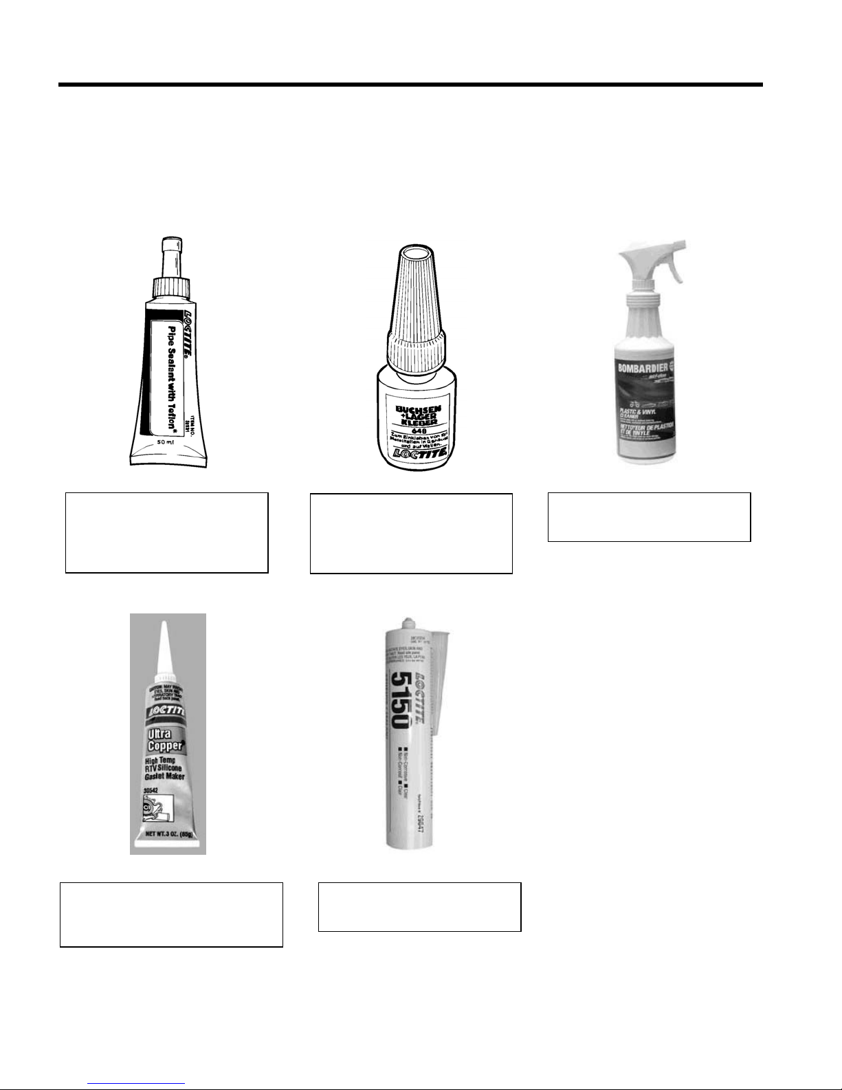
MANDATORY SERVICE PRODUCTS
Loctite RC/609, 10 ml
Retaining compound
P/N 413 703 100
Loctite 271, 10 ml
High strength
threadlocker
P/N 293 800 005
Loctite 243, 10 ml
Medium-strength
threadlocker
P/N 293 800 015
Sealing compound, 30 ml
P/N 420 297 905
Loctite Primer, 128g
P/N 413 708 100
Loctite 515, 50 ml
Paste gasket
P/N 413 702 700
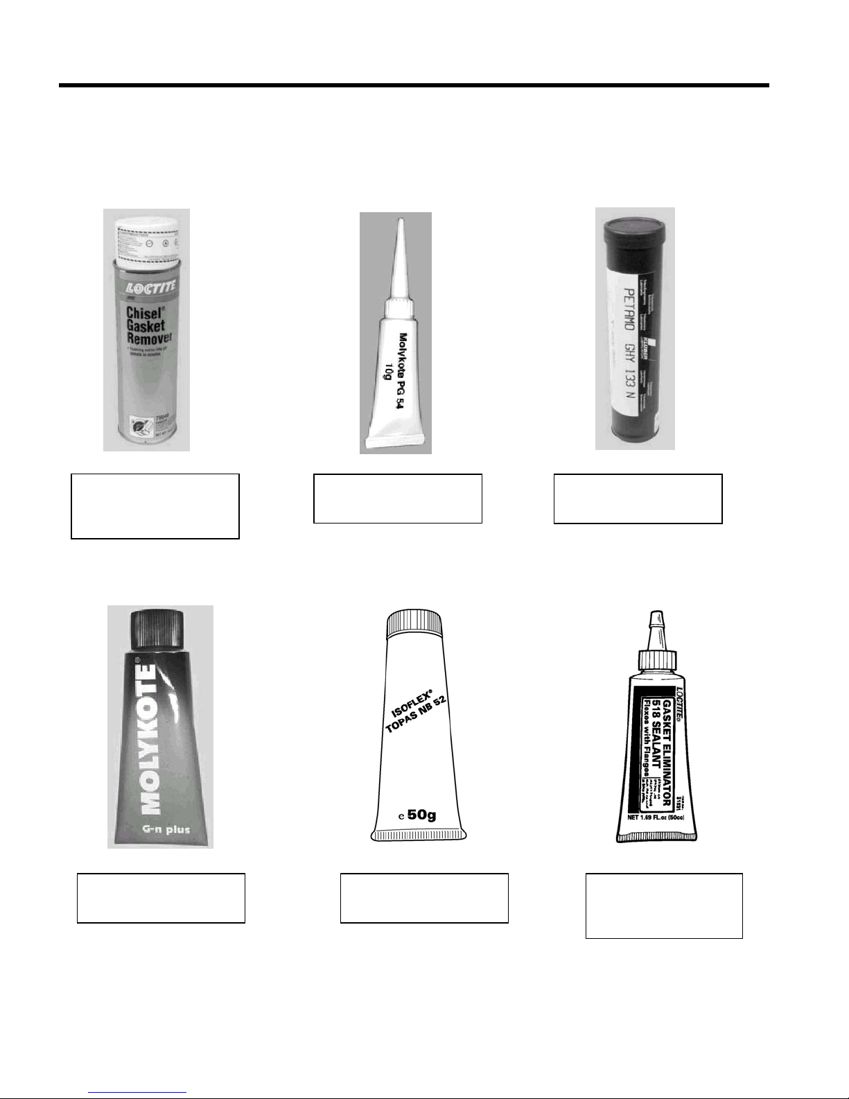
MANDATORY SERVICE PRODUCTS (continued)
Loctite 518, 50 ml
Gasket Paste
P/N 293 800 038
Loctite chisel, 510g
Gasket/paint remover
P/N 420 899 763
Molykote PG 54, 10g
P/N 420 899 763
Petamo Grease
P/N 420 899 271
Molykote G-n plus. 50g
P/N 711 297 433
Isoflex Grease, 50g
P/N 293 550 021
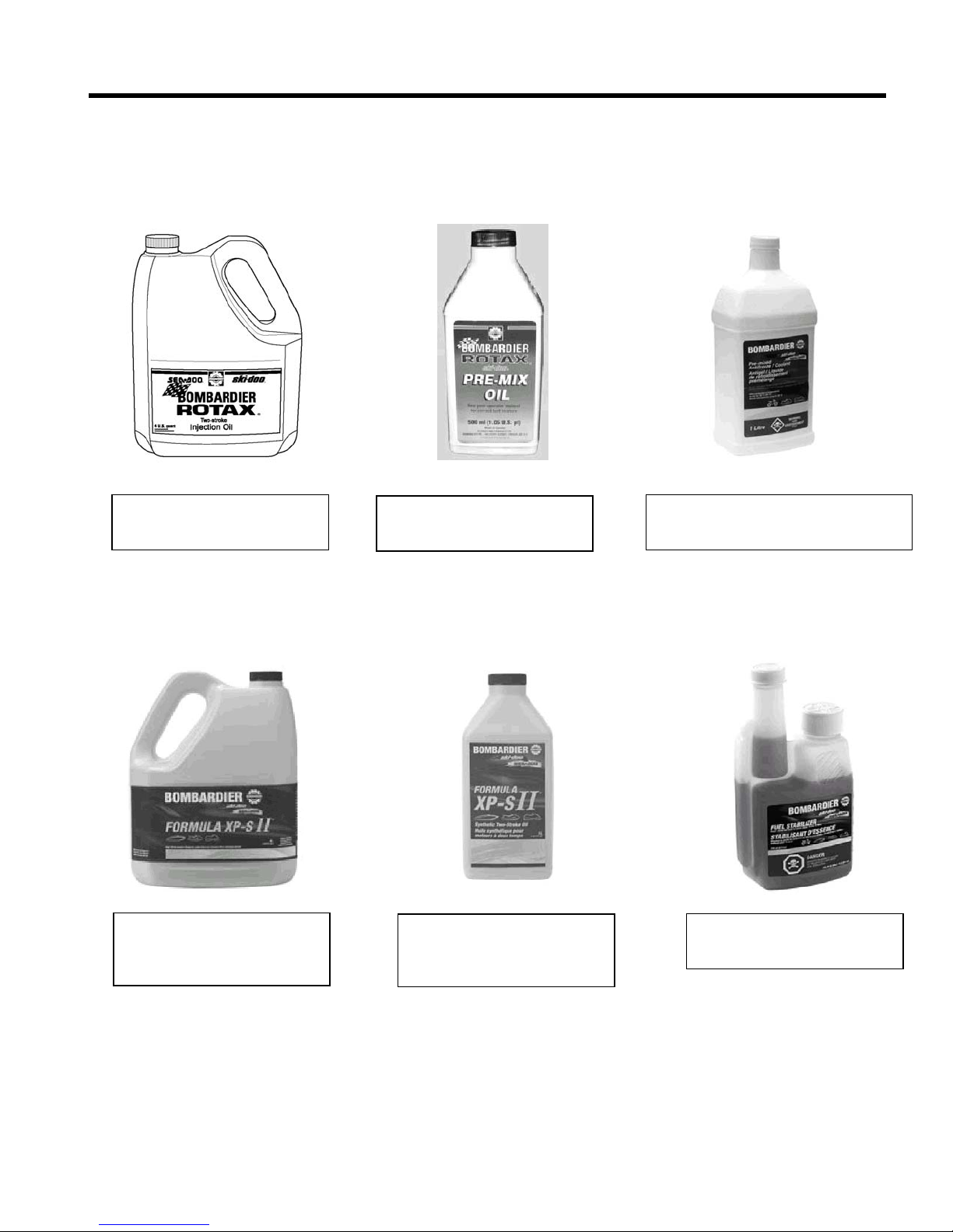
RECOMMENDED SERVICE PRODUCTS
Bombardier injection oil
3 x 4 litres P/N 413 803 000
Synthetic injection oil
Bombardier Formula XP-S II
3 x 4 litres P/N 293 600 046
Synthetic injection oil
Bombardier Formula XP-S II
12 x 1 litre P/N 293 600 045
Pre-mix oil
12 x 500ml P/N 413 803 100
Premixed coolant 50/50
16 x 1 litre P/N 293 600 038
Fuel stabilizer
12 x 8 oz P/N 413 408 600
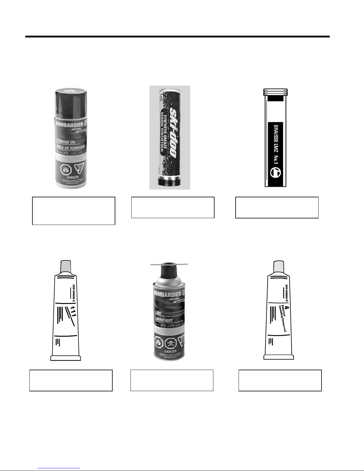
RECOMMENDED SERVICE PRODUCTS (continued)
Storage oil 12 x 350 g
Canada P/N 413 711 600
USA P/N 413 711 900
Synthetic Grease 400 g
P/N 413 711 500
LMZ Grease No 1, 400 g
P/N 413 707 500
Molykote 111, 50 g
P/N 413 707 000
Bombardier lube
12 x 14 oz P/N 293 600 016
Silicone dielectric grease, 3 oz
P/N 293 550 004
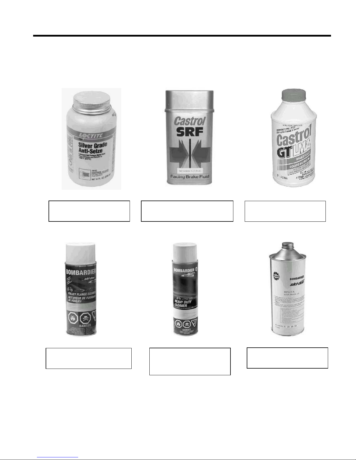
RECOMMENDED SERVICE PRODUCTS (continued)
Anti-seize compound, 236 ml
P/N 293 800 070
Brake fluid SRF ( DOT 4 )
P/N 293 600 063
Brake fluid GTLMA (DOT 4)
P/N 293 600 062
Heavy Duty Cleaner
400 g P/N 293 110 001
4 litres P/N 293 110 002
Shock oil 32 oz
P/N 293 600 035
Pulley flange cleaner, 320 g
P/N 413 711 809
RECOMMENDED SERVICE PRODUCTS (continued)
Loctite 592, 50 ml
Pipe sealant
P/N 293 800 018
Loctite 648, 5 ml
High temperature and strength
retaining compound
P/N 413 711 400
Plastic and vinyl cleaner
P/N 413 711 200
Loctite Ultra Copper, 80 ml
High temperature RTV sealant
P/N 293 800 090
Loctite 5150, 300ml
P/N 293 800 066

TABLE OF CONTENTS
GENERAL INSTRUCTIONS
PERIODIC MAINTENANCE
FUEL SYSTEM
ENGINE REMOVAL
REWIND STARTER
COOLING SYSTEM
ENGINE (CYLINDERS / HEAD / BASE)
PRIMARY TRANSMISSION SYSTEM
SECONDARY TRANSMISSION SYSTEM
HYDRAULIC BRAKE SYSTEM
FRONT FORK AND TWIN-AXIS SKI
REAR SUSPENSION, SHOCKS AND TRACK
CHASSIS AND STEERING
ELECTRICAL SYSTEM
DIMENSIONS AND TOLERANCES
WIRE, CABLE AND HOSE ROUTING
1
2
3
4
5
6
7
8
9
10
12
13
14
15
16
11

GENERAL INSTRUCTIONS 1 - 1
FIRST CONTACT
The SNOW HAWK™ is a completely new type of vehicle.
Technically speaking, it is a cross between a snowmobile and a
motorcycle. However, its behaviour depends on the conditions in
which it is used. Sometimes, it will react more like a bike while
at other times, it will react more like a snowmobile or a jetski.
Describing exactly how the SNOW HAWK™ behaves is difficult.
This is why we recommend that you take the time to become
acquainted with your machine in an area free of any obstacle.
This first contact should take place at low speed, with a series of
basic manoeuvres that will allow you to learn about the reactions
of the vehicle.
A good exercise is to follow a "figure 8" trajectory because this
will allow you to experiment with right- and left-hand turns
followed by accelerating and braking.
Turning can be done by steering right or left, keeping in mind the
speed of the vehicle, the snow conditions and how quickly you
want to change direction.
◆WARNING
Some people enter a turn by stretching out a leg on the
inside of the turn and letting the foot slide over the
ground (a technique used in motocross). We advise
against this practice which could cause severe injuries if
your foot should sink into the snow. We rather suggest
keeping both feet on the footpegs as much as possible.
An upright position, with the knees clutching the gas tank and
the elbows pointing away from the vehicle, will give a sense of
security and provide greater freedom of movement while
accelerating or slowing down.
◆WARNING
The greatest danger in using this vehicle is the perception
you may have of how competent you are. Overestimating
how competent you are can result in hazardous situations
both for yourself and for other trail users.
Do not forget to take all the time that is necessary for you to
practice and feel comfortable at low speeds before attempting
high-speed manoeuvres. You will then be able to fully
appreciate the joy of driving.
GENERAL INSTRUCTIONS 1 - 2
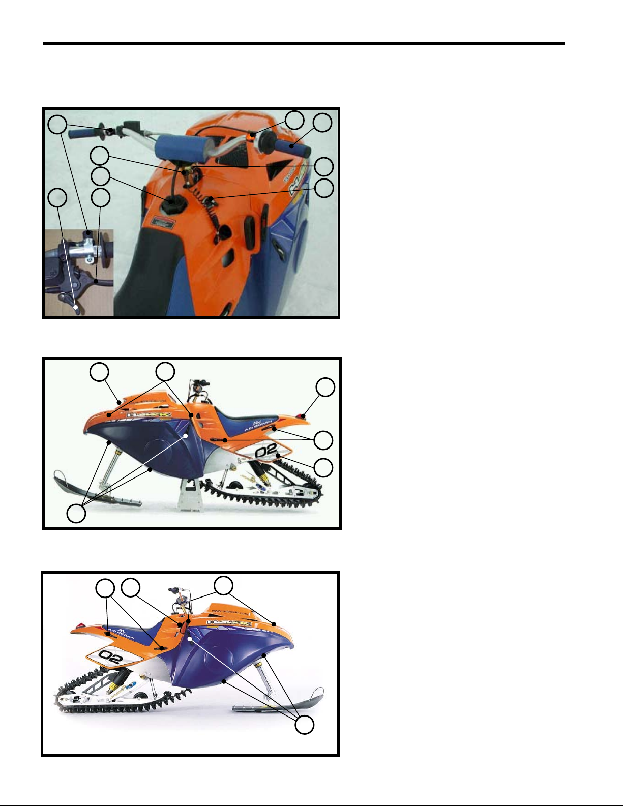
LOCATION OF MECHANISMS AND CONTROLS (503 SHOWN, 600HO IDENTICAL)
1. Throttle control
2. Brake lever
3. Parking brake lever
4. Engine-cutoff (tether)
5. Gas tank cap
6. Dimmer switch
7. Choke control
8. Emergency-stop button
9. Temperature Light
10. Hood latches (4)
11. Rear module latches (4)
12. Bellypan latches (6)
13. Kick stand
14. Headlight
15. Stop and tail light
16. Recoil starter handle
17. Hood latches (4)
18. Rear module latches (4)
19. Bellypan latches (6)
10
11
12
13
14
15
16 17
18
19
6
2
3
1
4
5
7
8
9
GENERAL INSTRUCTIONS 1 - 3
FUEL
This vehicle is powered by a two-stroke engine that uses a pre-
mixed gasoline and oil mixture.
Gasoline: Regular unleaded gas with a minimum octane
rating of 89 (R+M)/2
Motor oil: Bombardier / ROTAX Formula XPS Synthetic
Pre-mix oil (P/N 293600045)
Mixture ratio: 40 : 1 (32 : 1 for break in and CAN safely be
used thereafter if desired)
Fuel tank capacity: 30 L (9.5 gallons)
▼CAUTION
A mixture in which the proportion of oil is too low will
cause piston failure. On the other hand, a mixture in
which the proportion of oil is too high will cause
excessive carbon deposits that will result in fouled spark
plugs and will affect performance.
Always mix in a proportion of 40 parts of gasoline for
each part of oil.
●
NOTICE:
oThe use of isop[ropyl alcohol (commonly known as “gas-
line antifreeze) is recommended in a ratio of 150 mL per
fuel tank in very cold temperatures.
oAvoid mixing oils of different brands.
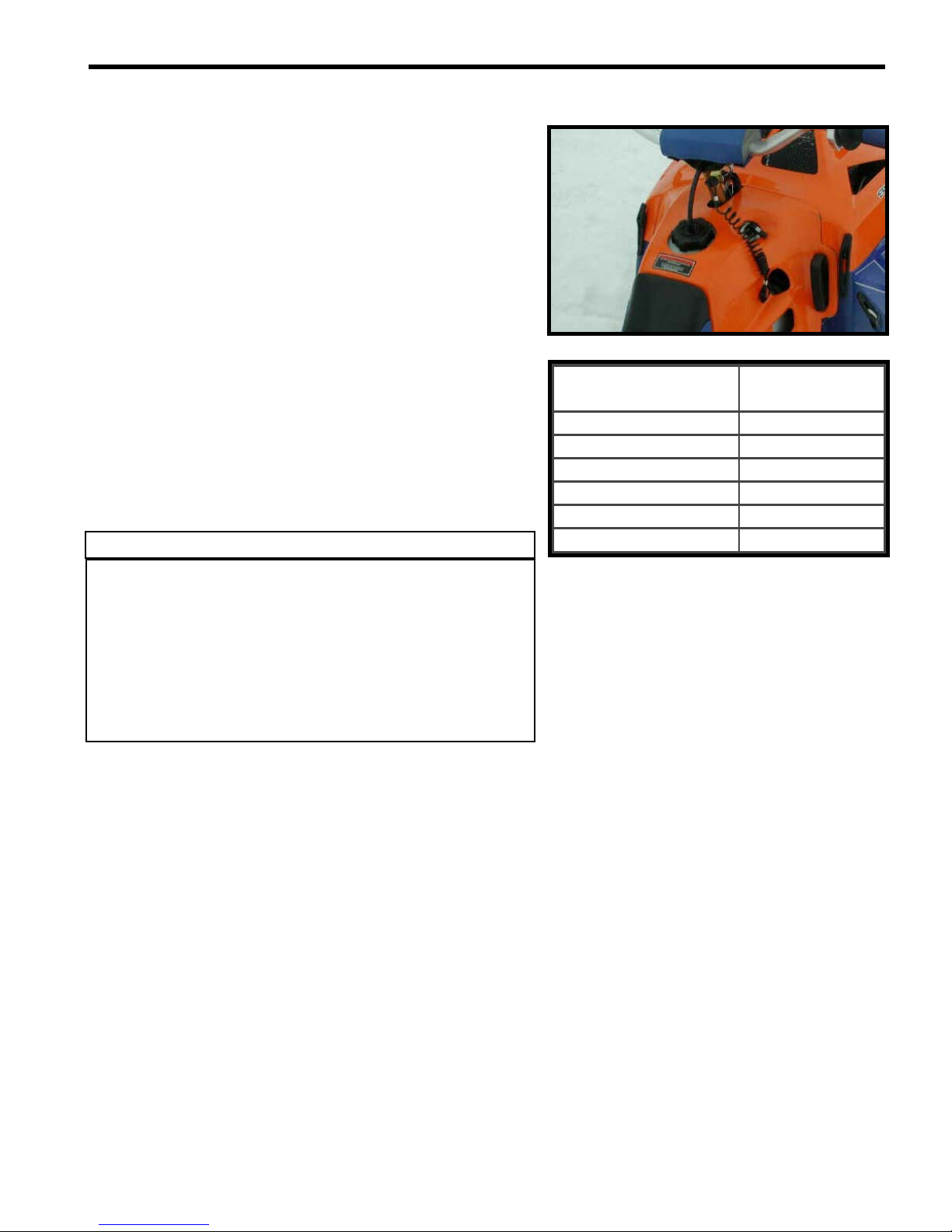
Gasoline
(
L
)
Oil
(
ml
)
5125
10 250
15 375
20 500
25 625
30 75
0
GENERAL INSTRUCTIONS 1 - 4
OPERATING INSTRUCTIONS
Pre-driving inspection
◆WARNING
A pre-driving inspection is of the utmost importance
before using the vehicle. Do not start the machine until
you are sure all mechanisms and controls are functioning
properly. Failing to proceed in the prescribed manner may
result in severe injuries or even death.
oMake sure the track and the idler wheels are not frozen and
that they move freely.
oDepress the brake lever and make sure the brake is fully
engaged before the end of the lever touches the handlebar.
The lever must return to its original position as soon as it is
released.
oTurn the twist throttle control a few times to make sure it
functions properly. The control must return automatically to
the idle position as soon as it is released.
oMake sure the engine cutoff switch, the stop light, the
headlight (high and low beams) and the tail light are in good
working order.
Starting the engine
oPut the cap of the engine cutoff (tether) switch in place. The
other end of the cord must be securely attached to the
driver.
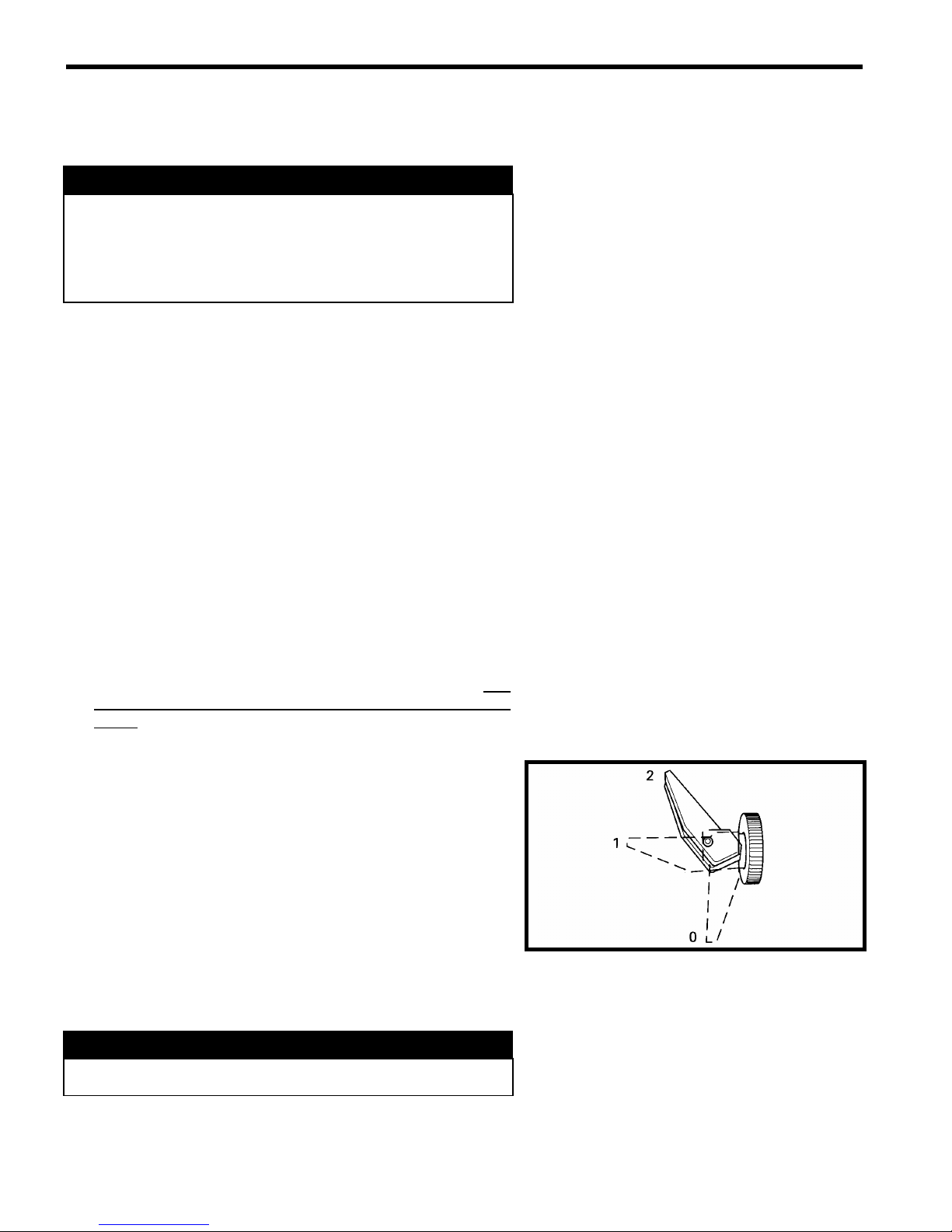
oIf the engine is cold, use the choke control.
0. Normal position (not activated)
1. Intermediate choke position
2. Full choke position
oStart the engine by firmly pulling the handle of the rewind
starter.
◆WARNING
Do not touch the throttle control while starting the engine.

GENERAL INSTRUCTIONS 1 - 5
Stopping the engine
oWhile the engine is idling, remove the engine cutoff cap
(tether) or press the emergency-stop button.
BREAK-IN PERIOD
Engine
▼CAUTION
A cautious break-in period of 10 to 15 hours is essential
before using the vehicle at full power. Failure to provide a
sufficient break-in period could result in severe engine
damage.
▼CAUTION
The timing of all Snow Hawk 600HO’s is retarded by 3ofor
a period of 1-hour during the first stages of the break-in
period. You may notice a slight increase in performance
and a reduction in fuel consumption after this time.
During the break-in period, the throttle control should not be
turned more than ¾ of its range. However, occasional periods
of brief, brisk acceleration and frequent speed variations
contribute to a good break-in. On the other hand, periods of
long, high acceleration, sustained high speed and engine
overheating are harmful during the break-in period.
◆WARNING
This vehicle is equipped with a liquid cooling system.
ALWAYS ride with the rear deflector pad installed and in
conditions where there is enough snow to properly cool
the engine. If the red temperature light on the steering
column should ever illuminate, stop immediately and let
the vehicle cool down, and then find some snow. NEVER
continue to operate the vehicle with the temperature light
illuminated as severe engine damage will occur.
▼CAUTION
A fuel : oil mixture of 32 : 1 MUST be used during the
engine break-in period.
◆WARNING
During the first hour of the break-in period the fluid levels
in the coolant reservoir and the small water pump oil
reservoir will go down slightly. This is perfectly normal.
Be sure to top-up these fluids with proper coolant (P/N
293600038) and proper oil (P/N 293600045).
GENERAL INSTRUCTIONS 1 - 6
Drive Belt
A new drive belt must be submitted to a 5-hour break-in period.
Avoid high-speed driving and brisk accelerations during this
period.
Inspection – 10 hours
A general inspection is recommended after the first 10 hours of
use. This inspection must be carried out by an authorized
SNOW HAWK ™ dealer.
●
NOTICE:
oMost of the wear in this vehicle occurs during the break-in
period.
oBolts and nuts can easily become loose in a new machine.
Make sure you check them regularly during this period.
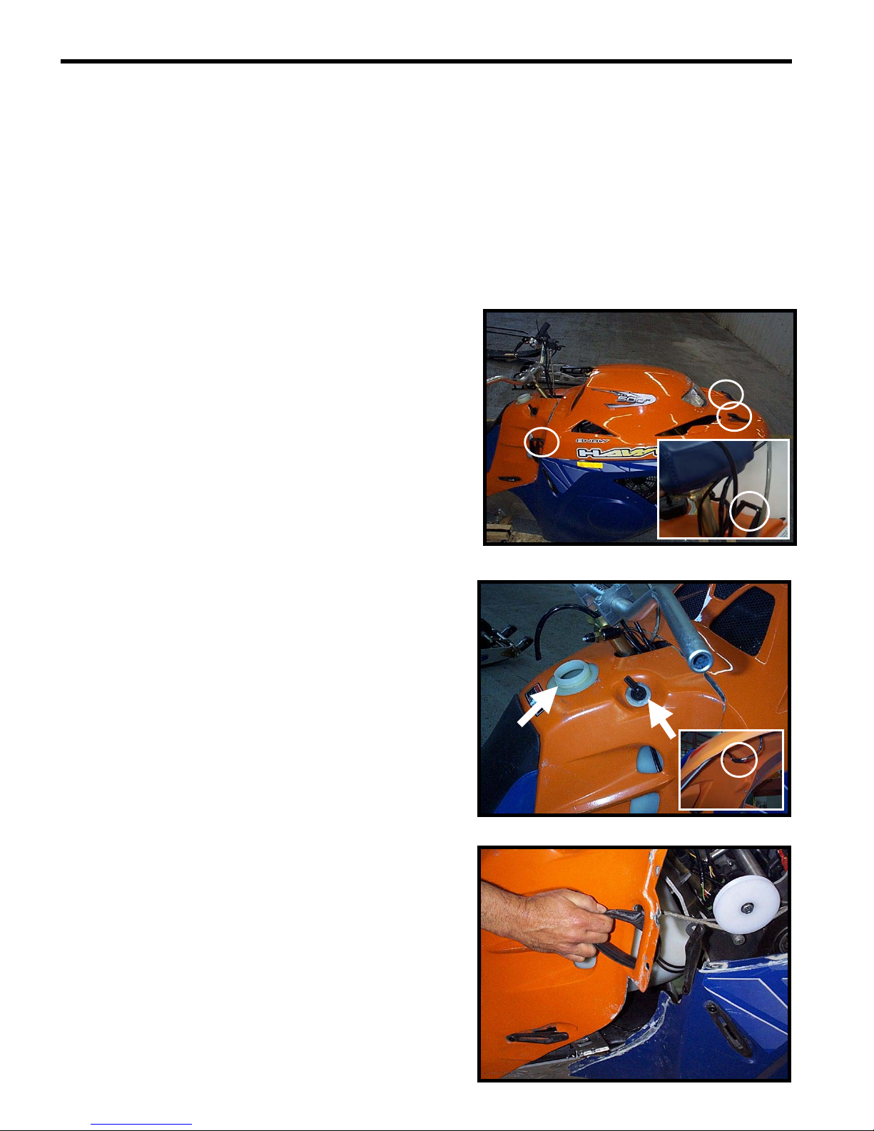
REMOVAL OF THE BODY PANELS (HOOD, REAR
MODULE AND BELLYPAN)
In order to work on the vehicle more easily and to access the
anchor ties, we suggest that you remove the rear module from
the vehicle. To do so, you must first remove the hood. Proceed
as follows:
oDisconnect the front headlight.
oUnhook the 4 rubber latches (2 / side).
oRemove the hood.
oRemove the fuel tank cap.
oSet the choke to the full position.
oUnplug the tail light connector located under the light
itself, underneath the rear fender.
o Release the rear module from its four rubber latches,
slip the rewind starter handle through the space
provided and remove the rear module.
GENERAL INSTRUCTIONS 1 - 7
Roll the two O-rings down and pull the two white plastic
collars down over the fork legs. To ensure that they will not
interfere, let them hang loose at the base of the fork leg.
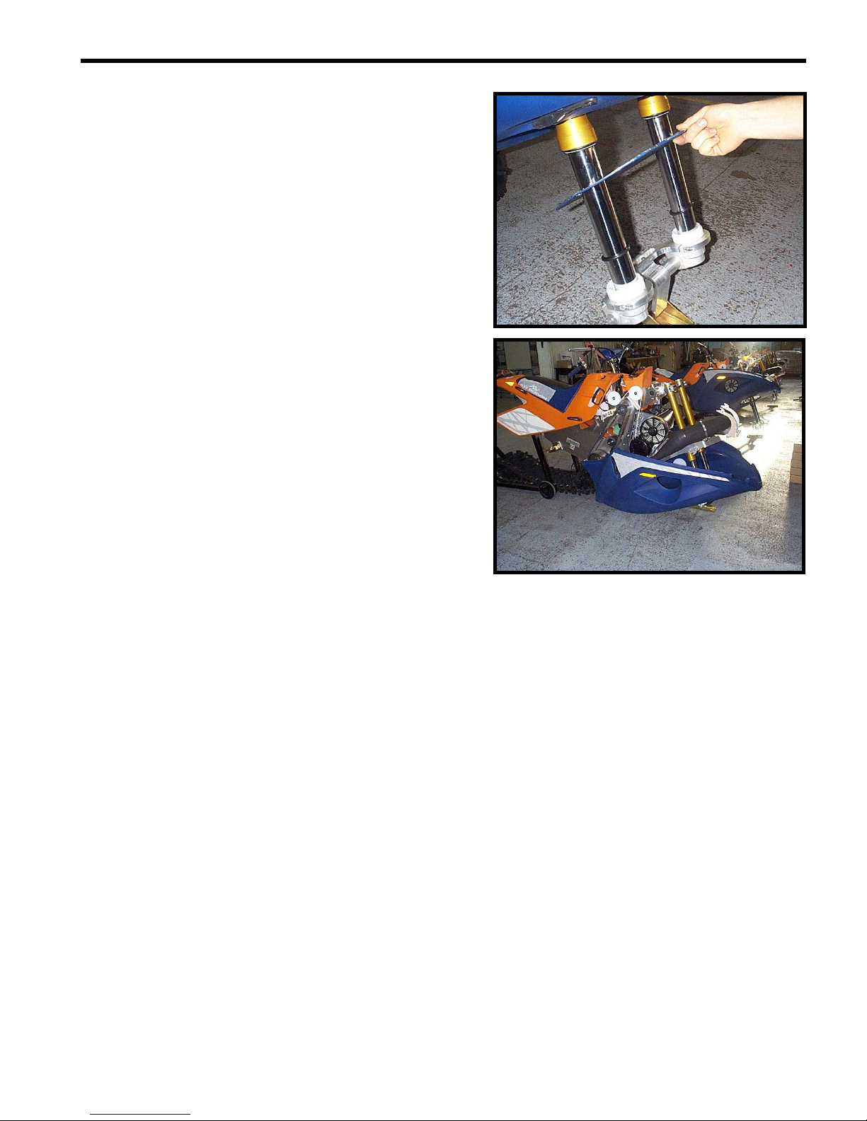
o Remove the circular fork disc
o De-latch the two rubber latches on the sides of the belly
pan (towards the rear of the vehicle)
o De-latch the four rubber latches on the bottom of the
belly pan.
o Descend the belly pan to floor level; most maintenance
can be performed with the belly pan in this position.
However, if it is required to completely remove the belly
pan, remove the single bolt attaching the ski to the fork.
At this point, a second person can lift the front of the
vehicle slightly and the belly pan can be slid out from
underneath.

PERIODIC MAINTENANCE 2 - 1
●
NOTICE:
Regular inspection and maintenance of the Snow Hawk is of utmost importance. Follow the guidelines in the table
below for optimum vehicle performance. Suggested intervals must be reduced if the vehicle is subjected to severe
usage conditions.
●
NOTICE:
V = Verify, A = Adjust, C = Clean, R = Replace one or several part(s), F = Replace fluid
Interval (Hrs)
Item
Fuel lines and connections
V
--
V
Carburetor ad
j
ustment
V
--
V
Throttle cable
V
- A - -
V
- A
Air Intake Filter
V
--
V
- C
Carburetor support bracket ---V
Starter cord
V
--
V
C
y
linder head bolts
V
--
V
En
g
ine support bolts
V
--
V
Exhaust s
y
stem
V
-
V
V
Coolant level
V
- A -
V
V
- F
Oil level
(
water pump oil reservoir
)
V
- A -
V
V
Cooling System (hose connections) V--V
Primar
y
drive belt
V
V
-
V
- R
Primar
y
and secondar
y
clutch
V
-
V
V
- C
Primar
y
clutch bolt
V
--
V
Secondary clutch pre-tension V - A - - V - A
Secondar
y
drive belt
(
co
g
belt
)
V
--
V
Co
g
sprockets
V
--
V
Tor
q
ue Limiter
V
--
V
- A
Taper Locks V--V
Brake fluid
V
--F
Brake pads
V
-
V
- R
V
- R
Brake microswitch V--V
Front Fork F-FF
Fork rubber cushion and bolt
V
-
V
V
Fork air bleeder screw
V
- A
V
- A
V
- A
V
- A
Twin axis ski bushin
g
s / nuts
V
- A -
V
- A
V
- A
Ski and runners VV-R
Suspension
V
-
V
-
Shocks
V
-
V
F
Track V - A - V - A V - A
Handlebar bolts
V
--
V
Steerin
g
components
V
-
V
V
Assembly bolts / nuts V--V-C
Spark plu
g
s
V
- A - R -
V
- A - R
V
- A - R
Spark plu
g
g
ap
V
- A - -
V
- A
Fuse
V
--
V
Headli
g
ht pro
j
ection/aim ---
V
- A
Lighting system, stop lamp and
emergency stop switch VV-V
2.7 Rear suspension and
track
2.9 Electrical system
15 Hrs
2.5 Brake system
2.4 Secondary
transmission system
2.6 Front suspension and
ski
2.8 Chassis
V - R as needed
65 Hrs
(yearly)
2.1 Carburetion
2.3 Primary transmission
system
2.2 Motor
Break-in
( ~ 10 Hrs. ) 5 Hrs
PERIODIC MAINTENANCE 2 - 2
2.1. CARBURETION
Fuel lines and connections
Check all hoses and connections in order to find and fix leaks
and/or to help prevent them.
Carburetor adjustment
For carburetor adjustment, refer to Chapter 3 - Fuel system
section.
Throttle cable
The throttle cable can be adjusted by setting the adjustment
mechanism on the throttle end of the throttle cable.
Air intake filter
The air intake filter must be cleaned at least once a year, or
more often under severe usage conditions. Clean the filter in a
solution containing a non-flammable cleaning solvant (such as
hot soapy water). Once dry, apply some light engine to the filters
to prevent the infiltration of water and dust.
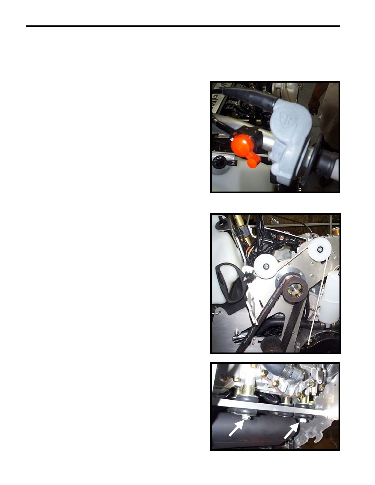
2.2. ENGINE
Recoil starter cord
Pull gently on the handle to unwind the full length of the cable.
Inspect the cable visually to detect any wear or other damage
that could eventually cause the cord to break.
Cylinder head bolts
Refer to the appropriate procedure in Chapter 7 – Engine
(Cylinders/Head/Base).
Engine support bolts
To carry out this operation, refer to the appropriate procedure in
Chapter 7 – Engine (Cylinders/Head/Base).

PERIODIC MAINTENANCE 2 - 3
Cold
Level
Exhaust system
Using a torque wrench, check the torque of the retaining bolts of
the exhaust manifold. Apply a torque of 10 N-m (1 kg-m, 7.4 lbf-
ft).
Then, proceed to a visual inspection of the system to detect any
leak or abnormality in the gasket material.
Cooling system
Inspect the coolant level in the coolant reservoir located on the
MAG side of the vehicle. If the coolant level is below the “Cold”
coolant mark when the vehicle is not warm or has not been
ridden within 30mins or more, add coolant until this line. Check
all of the hoses / hose connections and ensure that there are no
fluid leaks in the system.
Other manuals for 600HO
1
Table of contents
Other Snow Hawk Offroad Vehicle manuals

Popular Offroad Vehicle manuals by other brands


Yamaha
Yamaha MM700A manual

Aria Child
Aria Child PowerSport W420AC-F01 Owner's manual and assembly instructions

Explorer
Explorer Patriot 430 Service manual

KAYO MOTOR
KAYO MOTOR AT125-B Service manual

Polaris
Polaris RZR XP TURBO S 2019 Owner's manual for maintenance and safety

Power Wheels
Power Wheels DLX39 owner's manual