SO-LOW FDC nCOMPASS User manual

INSTRUCTIONS: SINGLE STAGE FREEZER
1.1 RANGE OF ENVIRONMENTAL CONDITIONS FOR WHICH
THIS EQUIPMENT IS DESIGNED
1. Indoor use.
2. Altitude up to 2000m.
3. Temperatures 15°C to 30°C ( 60°F TO 85°F )
4. Recommended humidity range of 30% to 90%.
5. Mains supply fluctuations up to -5% to +10% of the nominal voltage.
6. Transient overvoltages typically present on the mains supply (overvoltage category II). Pollution
degree 1.
CAUTION! THIS FREEZER IS PROVIDED WITH AN INPUT CIRCUIT
PROTECTIVE DEVICE WHICH SHALL BE MAINTAINED AND SERVICED
BY QUALIFIED PERSONNEL ONLY.
FUSES OR BREAKERS USED INSIDE PROTECTIVE DEVICE
15A OR 20A 250V TIME DELAY
WARNING! UPLUG FREEZER BEFORE ANY TECHNICAL SERVICE IS
PREFORMED ON THE UNIT!
CAUTION! DO NOT POSITION EQUIPMENT SO IT IS DIFFICULT TO
DISCONNECT FROM THE POWER SUPPLY.
1.2 STARTING INSTRUCTIONS
1. Plug the freezer into the proper outlet with an adequate power supply.
2. Confirm the freezer has at least 6” of air space on each side, for air circulation.
3. Turn the refrigeration switch (located in back of unit) to the ON position (if applicable).
4. The compressor(s) will start to operate and pull down to the set point on the
temperature control.
5. When the freezer reaches the set point, the compressor(s) will cycle on and off to
maintain the set point desired by the user on the temperature control.

1.3 CLEANING PROCEDURE
1. Wipe down the exterior of the freezer with a soft cloth and spray type polish.
2. If frost builds up in the chamber, a bucket and ice-scraper can be used to remove the ice.
If excessive ice builds up, the unit can be defrosted (see below).
1.4 DEFROST PROCEDURE
1. Remove any product in the freezer and store it in a back-up freezer or elsewhere.
2. Unplug the freezer, and open the freezer front door / lid.
For upright units, use a cloth to protect the control from dripping water.
3. Air out the freezer for at least 12 hours, allowing the unit to reach room temperature.
4. Take a rag and wipe up all the excess water in the unit (melted frost).
5. Plug the unit in and set your temperature to the desired setpoint
6. Once the desired temperature is reached, add product back into the unit.
NOTE: It is recommended to slowly re-add your product into the freezer to prevent
an extreme load on the compressors, which could shorten freezer life expectancy.
1.5 AUTOMATIC STARTING SYSTEM
The automatic starting system is provided on all freezer systems in case of power failure.
If there is an electrical power interruption to the unit and power is not restored
immediately, the unit will automatically start up whenever power is returned.
ATTENTION: Always leave the refrigeration switch in ON position, as this will
automatically activate the automatic starting system.
Single Stage
After power restoration, the single stage will start to operate and begin to pull down to
setpoint temperature.
CAUTION! COVER SCREEN ON BACK OF FREEZER TO BE REMOVED BY
AUTHORIZED PERSONNEL ONLY. FOR CONNECTIONS TO THE
EXTERNAL ALARM COVER SCREEN MUST BE REPLACED BEFORE
PUTTING FREEZER INTO SERVICE. FAILURE TO REINSTALL COVER
COULD RESULT IN HAZARD.

1.7 WARNING SYMBOLS
BLACK WITH YELLOW
BACKGROUND
LIGHTNING
BOLT
CAUTION: RISK OF
ELECTRICAL
SHOCK
BLACK WITH YELLOW
BACKGROUND
EXCLIMATION
POINT
CAUTION: REFER TO
ACCOMPANYING
DOCUMENTS
1.8ALARM SYSTEM
MODEL
OPERATION INSTRUCTIONS
FDC nCOMPASS
Alarm will automatically activate when freezer is connected to a
power source.
FDC 4000
Alarm will automatically activate when the freezer reaches set point
or 8 hours after the unit has been first plugged in.
FDC 4100
Manually activate the alarm by moving the toggle switch to the on
position once the freezer reaches setpoint.
PARTLOW 1160
Manually activate the alarm by moving the toggle switch to the on
position once the freezer reaches setpoint.
The alarm will not sound again until the temperature varies 12°C (20°F) from the
temperature control set point. Please note that the alarm will sound if there is a power
outage to the freezer.
Alarm system should be tested every 30 days.
Non-rechargeable batteries should be changed approximately every two years.
Rechargeable batteries should be changed approximately every three years with
lead acid rechargeable 12 Amp per hour, model PS-12120F2 or equivalent.

1.9 ALARM BATTERY TESTING
If applicable, the alarm switch has a test position that can be used anytime to see if the
battery is charged or if the buzzer is working properly.
OPTIONAL EQUIPMENT –DRY CONTACT ALARM RELAY
Located on the back of the freezer is a terminal strip marked ALARM RELAY CONTACTS.
Rating of this connection:
ALARM RELAY CONTACTS CONNECTION RATING
PARTLOW 1160
FDC 4100
FDC 4000
FDC nCOMPASS
10A 250VAC
10A 250VAC
2A 125 VAC
2A 250 VAC
10A 30VDC
10A 30VDC
2A 30 VDC
2A 30 VDC
RED –NORMALLY CLOSED
WHITE –COMMON
BLUE –NORMALLY OPEN
CAUTION! IF IT IS NECESSARY TO REMOVE METAL COVER SCREEN ON
BACK OF FREEZER TO MAKE CONNECTIONS TO ALARM RELAY, COVER
MUST BE REPLACED BEFORE FREEZER IS PUT INTO OPERATION
2.0 TEMPERATURE CONTROL
This freezer includes a digital temperature control which displays the setpoint and actual
temperature of the unit on the display screen.
The temperature control is manually adjustable to the desired temperature in 1° C
increments within the limits of the control range.
WARNING
Unauthorized entry into this control will void warranty.
SO-LOW CONTROL MODELS
PARTLOW 1160
FDC 4100
FDC 4000
FDC nCOMPASS
PARTLOW 1160
FDC 4100
SO-LOW
T
S
FDC 4000
“”””””””””
“””””””””
“””””””””””
“”””””””””
FDC
nCOMPASS

FDC nCompass
VERSION 6.1.17
Notes, cautions and warnings appear throughout this book to draw your attention to important
operational and safety information.
A “NOTE” marks a short message to alert you to an important detail.
A “CAUTION” safety alert appears with information that is important for protecting your
equipment and performance.
A “WARNING” safety alert appears with information that is important for protecting you, others and
equipment from damage. Pay very close attention to all warnings that apply to your application.
This symbol (an exclamation point in a triangle) precedes a general CAUTION or WARNING
statement.
This symbol (a lightning bolt in a lightning bolt in a triangle) precedes an electric shock hazard
CAUTION or WARNING safety statement.
Future Design Controls, Inc.
7524 West 98th Place
Bridgeview, IL 60455
Tel: (888) 751-5444
Fax: (888) 307-8014

FDC nCompass
VERSION 6.1.17
The nCompass display is split into two sections; the upper icon bar and bottom main display area.
The basic functions and settings for the upper Icon Bar are listed below:
The menu icon will open the main menu for navigating to the different control and
monitoring screens. Menu items will dynamically appear providing available options
based on the system area the user is in, i.e., security, data logging, setup, etc.
The information (help) icon will display text based help associated with the current
screen. Help is available in three languages, English, Spanish and French based on
the user selection in the offline setup of section of nCompass.
The home icon will return the user to the main view from anywhere in the nCompass
application. The main view is set by the OEM in the nCompass configuration and can
be the single or dual loop, trend, alarm, alarm history, event or digital IO view.
The alarm icon will appear and flash when a new system alarm occurs. Pressing the
alarm icon will take the user directly to the alarm monitor screen in order to view and
/or reset the active alarm condition.
The speaker icon will open the volume control menu, which controls the audible level
of temperature and condition alarms. The volume setting of “100”is the factory default
setting. Moving the volume dial to the “0”will disable the audible alarm.
IMPORTANT: Do not use any sharp or metal objects on the touch screen as they may damage the
surface. Also be sure that hands and fingers are free from oils or chemicals which may
mar the surface of the touch screen
Attention: Loading time between menu screens or parameter selection screens may vary.
Some menu screens may require several seconds to load before the information is displayed.
Pushing the display several times while a menu or parameter is loading may result in menus
being opened, or parameters being changed unintentionally.
Icon Bar
Main Display

FDC nCompass
VERSION 6.1.17
The nCompass display is split into two sections; the upper icon bar and bottom main display area.
The basic functions and settings for the bottom Display Area are listed below:
LOCATION
FUNCTION
ICON
DESCRIPTION
A
Temperature
Scale
This display shows the temperature scale of the freezer (°C or °F).
Pressing this display allows you to reset the historical maximum and minimum
temperature (see location C for additional information).
B
Setpoint
Temperature
This number display shows the setpoint temperature of the unit.
Press and release the red numbers to change the setpoint temperature. Input the
new setpoint temperature with number pad and press and release the done key.
C
Actual
Temperature
This number display shows the actual temperature inside the unit.
Pressing this display will show the historical maximum and minimum temperatures.
The historical record can be set by pressing the Temperature Scale button.
D
Snowflake
This display shows when the refrigeration system compressors are cycled on.
There is no additional functionality of this icon.
E
Alarm Test
This display shows if the alarm test is active. Pressing this display will move the
slider to the ON position, and sound the audible alarm as a test. Note that if the
volume is set to “0”, no alarm will sound. Press the icon again to reset it to OFF.
F
Power
Connection
This display shows the current power connection for the control. If the control is on
AC power, a green plug icon will appear. If the control is on backup battery power, a
red battery icon will appear. There is no additional functionality of this icon.
Note: When changing unit setpoint temperature, the unit must have active power from an
electrical grid for at least 5 minutes after the setpoint temperature is changed, for the new
setpoint to become permanent.
If electrical power to the control is lost before the 5 minute setpoint adjustment period,
the unit will restore itself to the last saved setpoint temperature on power start-up.
C
E
B
D
A
F

FDC nCompass
VERSION 6.1.17
In the case of power failure, the nCompass temperature control switches from AC power to a backup
battery located inside the electrical panel of the freezer. This battery is the 6 volt rechargeable type, and
is designed to last approximately 24-48 hours during power failure. It is recommended to test the battery
on a regular basis and replace the battery when needed (approximately 3-5 years).
ATTENTION: The battery backup system only powers the control during power failure.
It does not power the refrigeration system, and the freezer will not run during power failure.
When unplugging the freezer to put it into storage, the power failure alarm will sound. To disable this
power failure alarm, you will need to disconnect the battery; which is located in the electrical panel.
To do this, complete the following procedure:
1. Locate the electrical panel on the side of the freezer.
2. Remove the screws with a Phillips screwdriver, and remove the panel.
3. Locate the battery (which is clearly marked) in the lower right hand corner.
4. Disconnect one lead from the battery by removing the connector on the battery.
5. When returning the unit to service, complete steps 1-4, but reconnect the unplugged battery in
step 4. Then plug the freezer into the outlet to restore power.
It is recommended to keep the freezer plugged in and running when possible. Leaving the unit
unplugged for long periods of time may shorten the life expectancy of the freezer.
SIDE OF FREEZER
ELECTRICAL PANEL BOX
CAUTION
RISK OF ELECTRICAL SHOCK
USE CAUTION NEAR ELECTRICAL CONNECTIONS

FDC nCompass
VERSION 6.1.17
The nCOMPASS controller plate located on the front of the chamber can be vertical or horizontal
depending on the orientation of your unit. Upright freezer models use the horizontal format (shown in
the picture below to the left). Chest freezer models use the vertical format (shown in the picture below to
the right).
UPRIGHT STYLE CHEST STYLE
STEP
DESCRIPTION
ICON
INSTRUCTIONS
1
Insert USB
Insert your USB Drive / Flash Drive into the USB port located on the front of
the control.
2
Home Menu
Press the menu icon, at the top of the display area.
This will open the Home menu.
3
Data Menu
Press the Data button, located in the Home menu.
This will open the Data panel. This menu controls how data is transfer to
your USB device.
4
Specify name
of Data File
(Optional) Enter the requested information into the File Name field. If no file
name is entered, the control will automatically generate a file name for you.
5
Save Data
Press the Save button, located in the Data menu.
6
Home
Press the home key, to return to the home screen.
7
Remove USB
Remove your USB Drive / Flash Drive from USB port located on the front of
the control.
nCOMPASS
SO-LOW
ENVIRONMENTAL
nCOMPASS
SO-LOW
ENVIRONMENTAL
USB PORT

FDC nCompass
VERSION 6.1.17
On the bottom of the freezer ( located either next to the electrical panel, or on the back of the unit ), is an
RJ45 ethernet connection port. This connection port can be used to connect the nCompass control to
your local computer network. When connected to your computer network the nCompass control has
access to the following functionality:
•VNC access for remote connection, for local network users.
When your local computer network also has internet access, the nCompass control has access to the
following functionality:
•Email (and text) alerts to a specified email address (or phone).
•Upload temperature data to an FTP server
EMAIL / TEXT ALARMS MAY NOT OPERATE DURING POWER FAILURE
IF YOUR NETWORK IS NOT PROPERLY CONFIGURED
The battery backup system on the freezer only powers the control during power failure. It does
not power any additional network systems which may be required for your internet to operate.
It is recommended to have your local network router, and modem, connected to a battery
backup, so the freezer’s internet connection will continue to operate during power failure.
Follow the below procedure for adjustments which require the DATA setting to be turned OFF.
Follow the below procedure for adjustments which require the DATA setting to be turned ON.
ATTENTION: While the DATA setting is turned OFF, temperature data will not be recorded.
1
Home Menu
Press the menu icon, at the top of the display area.
This will open the Home menu.
2
Data Menu
Press the Data button, located in the Main menu.
This will open the Data panel.
3
DATA
Press the Data button on the right hand side to turn the data light off/on.
A BRIGHT green light indicates the data is turned on.
A DARK green light indicates the data is turned off.
4
Home
Press the home key, to return to the home screen.

FDC nCompass
VERSION 6.1.17
The nCOMPASS temperature controller has an adjustable temperature scale ( Celsius of Fahrenheit ).
Note: Once the temperature scale has been changed, all past and future temperature data will
be converted into the selected temperature scale.
STEP
DESCRIPTION
ICON
INSTRUCTIONS
1
DATA OFF
Follow the steps in the DATA SETTINGS ADJUSTMENTS
to turn the data OFF.
2
Home Menu
Press the menu icon, at the top of the display area.
This will open the Home menu.
3
Settings
Press the settings button, located in the Home menu.
This will open the Settings panel.
4
Settings Menu
Press the menu icon, at the top of the display area.
This will open the settings menu.
5
Offline Mode
Press the offline button, located in the Settings Menu.
Press YES when prompted to open the control in offline mode.
This will open the Offline mode panel.
6
Offline Menu
Press the menu icon, at the top of the display area.
This will open the offline menu.
7
Units
Press the units button, located in the Offline menu.
This will open the units panel.
8
Select Scale
Select the temperature scale (Celsius of Fahrenheit) you wish to display.
A BRIGHT yellow icon indicates the scale has been selected.
A DARK yellow icon indicates the scale has not been selected.
9
Home
Press the Home button when completed, to return to the home screen.
10
DATA ON
Follow the steps in the DATA SETTINGS ADJUSTMENTS
to turn the data ON.

FDC nCompass
VERSION 6.1.17
The nCOMPASS temperature controller has an adjustable offset to calibrate the temperature control.
Note: Adjustments made to the temperature offset will calibrate the control. Adjusting this
setting improperly can cause inaccuracies and fluctuations in the temperature of the freezer.
STEP
DESCRIPTION
ICON
INSTRUCTIONS
1
DATA OFF
Follow the steps in the DATA SETTINGS ADJUSTMENTS
to turn the data OFF.
2
Home Menu
Press the menu icon, at the top of the display area.
This will open the Home menu.
3
Settings
Press the settings button, located in the Home menu.
This will open the Settings panel.
4
Settings Menu
Press the menu icon, at the top of the display area.
This will open the settings menu.
5
Offline Mode
Press the offline button, located in the Settings Menu.
Press YES when prompted to open the control in offline mode.
This will open the Offline mode panel.
6
Offline Menu
Press the menu icon, at the top of the display area.
This will open the offline menu.
7
Calibrate
Press the calibrate icon, located in the Offline menu.
This will open the calibration menu.
8
User Calibration
Press “Perform User Calibration Offset”
This will open the user calibration menu.
9
Low Point Offset
Enter the desired offset in the Low Point Offset Field.
10
Done
Press “Done”when completed.
11
Home
Press the Home button when completed, to return to the home screen.
12
DATA ON
Follow the steps in the DATA SETTINGS ADJUSTMENTS
to turn the data ON.

FDC nCompass
VERSION 6.1.17
The nCOMPASS temperature controller has an adjustable alarm differential, to set when the freezer
goes into alarm state.
Note: Improper adjustments to the Alarm Differential could result in the alarm not operating as
designed. The factory configuration for the Alarm Differential is 12.
It is not recommended to set the Deviation Band to a value less than 10, as this may
result in the alarm sounding during the freezers normal temperature cycle.
STEP
DESCRIPTION
ICON
INSTRUCTIONS
1
Home Menu
Press the menu icon, at the top of the display area.
This will open the Home menu.
2
Settings
Press the settings button, located in the Home menu.
This will open the Settings panel.
3
Settings Menu
Press the menu icon, at the top of the display area.
This will open the settings menu.
4
Alarm
Press the alarm button, located in the Settings menu.
This will open the Alarm panel.
5
Deviation Band
Set the Deviation Band value to the desired Alarm Differential.
Note: Alarm #1, and Alarm #2 can be set for different values for
different alarm states.
6
Home
Press the Home button when completed, to return to the home screen.
The nCompass Control uses a custom Windows CE based software stored on an internal hard drive
inside the device. Future Design Controls Windows CE based nCompass display and Control Module
(Idec PLC) software (listed as “SOFTWARE” in this document) is protected by copyright laws and
international copyright treaties, as well as other intellectual property laws and treaties. All ownership and
rights remain with Future Design Controls. The nCompass Control does not receive software updates
though the internet, or other means.
DO NOT ATTEMPT TO REMOVE THE HARD DRIVE FROM THE DEVICE.
DO NOT ATTEMPT TO REMOVE THE SD CARD FROM THE DEVICE.
To remove user data from the SD Card, please contact Future Design Controls, Inc. (888-751-5444)
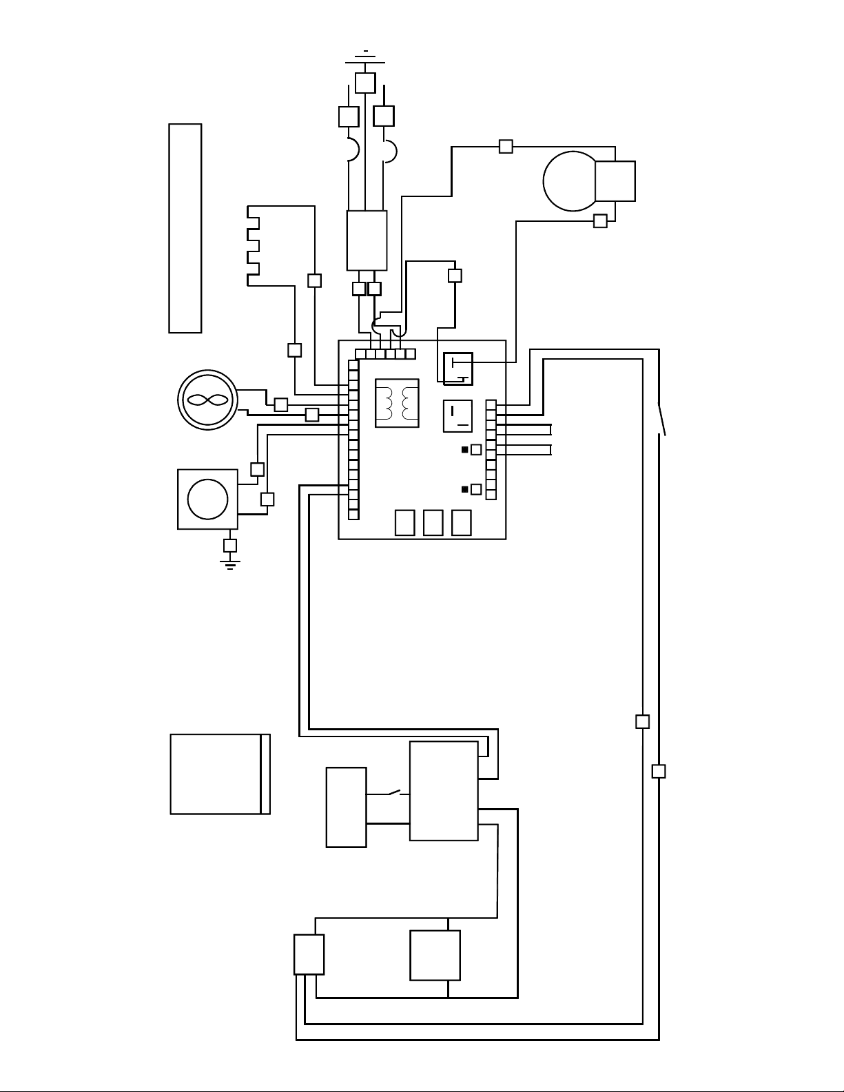
COLOR CODE CHART
YELLOW = Y
ORANGE = O
BLUE = B
RED = R
WHITE = W
BLACK = BK
COND. FAN(S)
TRANSFORMER
(IF APPLICABLE)
TEMP. REC.
(IF APPLICABLE)
COMPRESSOR
HEATER(S)
B
R
B
B
R
R
ELECTRICAL DIAGRAM
NOTE: ACCESSORIES ARE CONNECTED TO AC TERMINAL STRIP
W
BK
GREEN/YELLOW = GY
GY
BK
W
GREEN = G
G
CIRCUIT BREAKER
TC INPUT
BK
230 VOLTS, 50/60 HERTZ, 1 PHASE
UPS
+-
CONTROLER
B 42
BLACK
BLACK
RED
BLACK
BATTERY
KEY SWITCH
+-
5-23-2017
BLACK
NC230 UPS SINGLE STAGE
(IF APPLICABLE)
REFRIGERATION SWITCH
(IF APPLICABLE)
BK
BK
BK
BK

EVAPORATOR
HEAT EXCHANGER
CAPILLARY TUBE
DRIER
COMPRESSOR
OIL SEPARATOR
(IF APPLICABLE)
REFRIGERANT FLOW CHART
FLSS
LOW SIDE VALVE
HIGH SIDE VALVE (IF APPLICABLE)
AIR COOLED CONDENSER

TO ENSURE YOU ARE PROVIDED THE CORRECT PARTS,
THE MODEL AND SERIAL NUMBER OF YOUR UNIT
MUST BE PROVIDED WHEN ORDERING.
COMPRESSOR MODEL
HP
VOLTAGE
HERTZ
PHASE
SO-LOW PART #
TECUMSEH AJB2433ZXA
1
115
50/60
1
AJB24-115
TECUMSEH AJB2433ZXD
1
208/220/230
50/60
1
AJB24-208
EMBRACO FFI12HBX
1/3
115
50/60
1
FF12-115
DANFOSS SC15FTX
1/3
115
50/60
1
SC15-115
DANFOSS SC18FTX
1/2
208/220/230
50/60
1
SC15-208
TEMPERATURE CONTROL PARTS
SO-LOW PART #
FDC 4100
4100
FDC 4000
4000
FDC nCOMPASS
nCOMPASS
CASCADE ELECTRICAL PARTS
SO-LOW PART #
Heater Harness No. H-200
217-VOLTAGE
Refrigeration Switch No. 2X464
TOGGLE
Condenser Fan Motor No. GE-5411 - 115/60/1
500-115
Condenser Fan Motor No. GE-5421 - 230/50-60/1
500-VOLTAGE
Electrical Cord No. 8-3 (Please Specify Voltage)
PWRCRD-VOLTAGE
Control Board No. CECB2TUV (Please Specify Voltage)
231-VOLTAGE
REFRIGERATION PARTS
SO-LOW PART #
Air Cooled Condenser No. 3CZ0602B
254
Heat Exchanger, No. HE-502
HX-SS
Drier No. C-052-S
256L
Capillary Tube No. CT-502
SSC-23
Oil Separator, Temprite Series 900 (If Applicable)
900
HARDWARE PARTS
SO-LOW PART #
Latch No. METL-L1-99
REX37L1-3
Chest Hinge
59-928M
Upright Hinge No. Polar 109-LH
59-928U
Cabinet Gasket
NX504B1
Lid or Door Gasket
PSOS
Grill No. 650H
356F, 356S
Sub-Lids (Must have Model Number)
SL-MODEL NUMBER
Inner Door (Must have Model & Serial Number)
357-MODEL NUMBER-SERIAL NUMBER
Clips & Rollers for Inner Doors (Quantity 10 minimum)
405
Shelves for Freezer (Must have Model Number)
4015-MODEL NUMBER
SS REFRIGERATION & HARDWARE PARTS LIST
This manual suits for next models
3
Table of contents
Other SO-LOW Freezer manuals


