SO-LOW PV85 Series User manual

ULTRA LOW FREEZER
U85 / C85 / PH85 / PV85 SERIES
INSTRUCTIONS
USER MANUAL
WARNING: READ BEFORE CONTINUING
To reduce the risk of fire, electric shock or injury to persons using this freezer, read all
instructions and follow basic safety precautions before using the unit, including the following:
Do not modify the plug provided with the freezer. If it will not fit the outlet,
have a proper outlet installed by a qualified electrician.
Do not position equipment so it is difficult to disconnect from the power supply.
freezer must be at least 6” away from any wall or object on any side.
While under warranty, do not attempt to repair or replace any part of the
freezer for servicing without first contacting the So-Low Service Department.
SAVE THESE INSTRUCTIONS
So-Low Environmental Equipment Company
10310 Spartan Drive
Cincinnati, OH 45215-1221
Tel: 513-772-9410
http://www.so-low.com
For customer service:
Email: sales@so-low.com
For parts replacement:
Email: parts@so-low.com
For technical support:
Email: service@so-low.com
CONTENTS

♦SYMBOLS AND STARTING INSTRUCTIONS………………………..
1
● MEANING OF ILLUSTRATED SYMBOLS…………………………………...
1
● STARTING INSTRUCTIONS…………………………………………………..
1
♦UNIT REQUIREMENTS………………………………………………….
2
●
PRE-INSTALLATION INFORMATION………………………………………...
2
♦PREVENTATIVE MAINTENANCE…..………………………………….
3
● FREEZER STORAGE PROCEDURE……………………………………..….
3
● ALARM BATTERY REPLACEMENT…...……………………………………..
4
● CLEANING PROCEDURE……………………………………………………..
5
● DEFROSTING PROCEDURE………………………………………………….
5
● CLEANING AIR CONDENSER………………………………………………... 6
♦UNIT OPERATION………………………………………………………..
7
● CHANGING SETPOINT / OPERATION TEMPERATURE………….………
7
♦ALARM OPERATION…………………………………………………….
8
● ALARM SYSTEM……………………………………………………………….. 8
● DRY CONTACT RELAY………………………………………………………..
8
♦CONTROL PROGRAMMING……………………………………………
9
● CONTROL KEYS & DISPLAYS………………………………………………..
9
● CONTROL DISPLAY VALUES………………………………………………... 10
● USER PARAMETER MODE…………………………………………………...
10
● PROGRAM PARAMETER MODE…………………………………………….
11
● CALIBRATION PROCEDURE………………………………………………...
12
♦FREQUENTLY ASKED QUESTIONS…………………………………..
13
♦REPLACEMENT PARTS LIST…………………………………………..
14
♦TECHNICAL SUPPORT………….………………………………………
15
♦MAINTENANCE CHECKLIST….………………………………………..
16
Explanation
SYMBOLS AND STARTING INSTRUCTIONS

ILLUSTRATED SYMBOLS
Various symbols are used in this safety manual in order to use the unit without
danger of injury and damage of the unit. Be sure that you understand the
warnings and cautions in this manual before operating the unit.
CAUTION
BLACK WITH YELLOW BACKGROUND
LIGHTNING BOLT
CAUTION, RISK OF ELECTRICAL SHOCK
WARNING
BLACK WITH YELLOW BACKGROUND
EXCLAMATION POINT
CAUTION, REFER TO ACCOMPANYING DOCUMENTS
1. Move the freezer to an indoor location, and plug the freezer into an appropriate
outlet with an adequate power supply. Consult your maintenance department for
additional information on the proper electrical configuration for this unit.
2. Once plugged in, the compressor(s) will start to operate and pull down to the
setpoint on the temperature control. The freezers default setpoint is -85°C for
cascade units, and -40°C for single stage units.
3. Allow the freezer to reach the setpoint temperature. Depending on the size of the
unit, this may take up to 12 hours.
4. Product can now be loaded into the freezer for storage.
To prevent overloading the cooling system, product should be
loaded gradually, in batches. Allow the temperature to recover to
setpoint before the next batch of product is loaded into the unit.
1
Unit Information
MEANING OF ILLUSTRATED SYMBOLS
UNIT REQUIREMENTS
STARTING INSTRUCTIONS
RANGE OF ENVIRONMENTAL CONDITIONS
FOR WHICH THIS EQUIPMENT IS DESIGNED
1. Indoor use.
2. Altitude up to 2000m.
3. Ambient temperatures 15°C to 30°C ( 60°F TO 85°F )
4. Recommended humidity range of 30% to 90%.
5. Mains supply fluctuations up to -5% to +10% of the nominal voltage.
6. Transient over-voltages typically present on the mains supply
(overvoltage category II). Pollution degree 1.
WARNING
DURING OPERATION THIS UNIT MUST REMAIN IN UPRIGHT
POSITION. DURING TRANSPORATION UNIT MUST NOT BE
TIPPED MORE THAN 45° FROM UPRIGHT POSITION.
CAUTION
UNPLUG UNIT AND SWITCH OFF ELECTRICAL BREAKER
BEFORE ANY TECHNICAL SERVICE IS PERFORMED.
CAUTION
COVERS ON BACK / SIDE OF FREEZER MAY ONLY BE
REMOVED BY AUTHORIZED PERSONNEL. FAILURE TO
RE-INSTALL COVER COULD RESULT IN HAZARD.
CAUTION
UNIT MUST BE OPERATED ON A DEDICATED ELECTRICAL
LINE. USING A NON-DEDICATED LINE MAY RESULT IN UNIT
STARTUP FAILURE.
CAUTION
ONLY PLUG THIS UNIT INTO THE PROPER OUTLET. DO
NOT ATTEMPT TO MODIFY PLUG IN ANY WAY. IMPROPER
USE OF THE ELECTRICAL PLUG WILL VOID WARRANTY.
WARNING
DO NOT POSITION EQUIPMENT SO IT IS DIFFICULT TO
DISCONNECT FROM THE POWER SUPPLY.
2
PRE-INSTALLATION INFORMATION
PREVENTATIVE MAINTENANCE
FREEZER STORAGE PROCEDURE

The unit can be turned off for storage by unplugging the unit from the wall
outlet and/or switching off the electrical breaker in the electrical box.
ATTENTION
RISK OF ELECTRICAL SHOCK
USE CAUTION NEAR ELECTRICAL CONNECTIONS
Once the unit is unplugged, the freezer will go into “Power Failure” alarm.
To disable the Power Failure alarm;
1. Locate the electrical panel on the side of the freezer.
2. Remove the screws with a Phillips screwdriver, and remove the panel.
3. Locate the battery (which is clearly marked) in the lower right hand corner.
4. Disconnect one lead from the battery by removing the connector on the battery.
5. When returning the unit to service, complete steps 1-4, but reconnect the
unplugged battery in step 4. Then plug the unit into the outlet to restore power.
NOTICE
SEE STARTING INSTRUCTIONS ON PAGE 1
WHEN PUTTING UNIT BACK INTO SERVICE.
3
PREVENTATIVE MAINTENANCE
ALARM BATTERY REPLACEMENT

NOTICE
THE LO-BAT (LOW BATTERY ALARM) IS NOT ABLE TO BE
SILENCED OR DISABLED.
TO REDUCE THE VOLUME OF THE ALARM UNTIL A
REPLACEMENT CAN BE INSTALLED, A PIECE OF TAPE CAN
BE PLACED OVER THE BUZZER HOLE ON THE CONTROL
To reduce the risk of fire, electric shock or injury to persons using this
freezer, read all instructions and follow basic safety precautions.
CAUTION
DISCONNECT THIS UNIT FROM THE POWER SUPPLY
BEFORE PERFORMING MAINTENANCE ON THE UNIT.
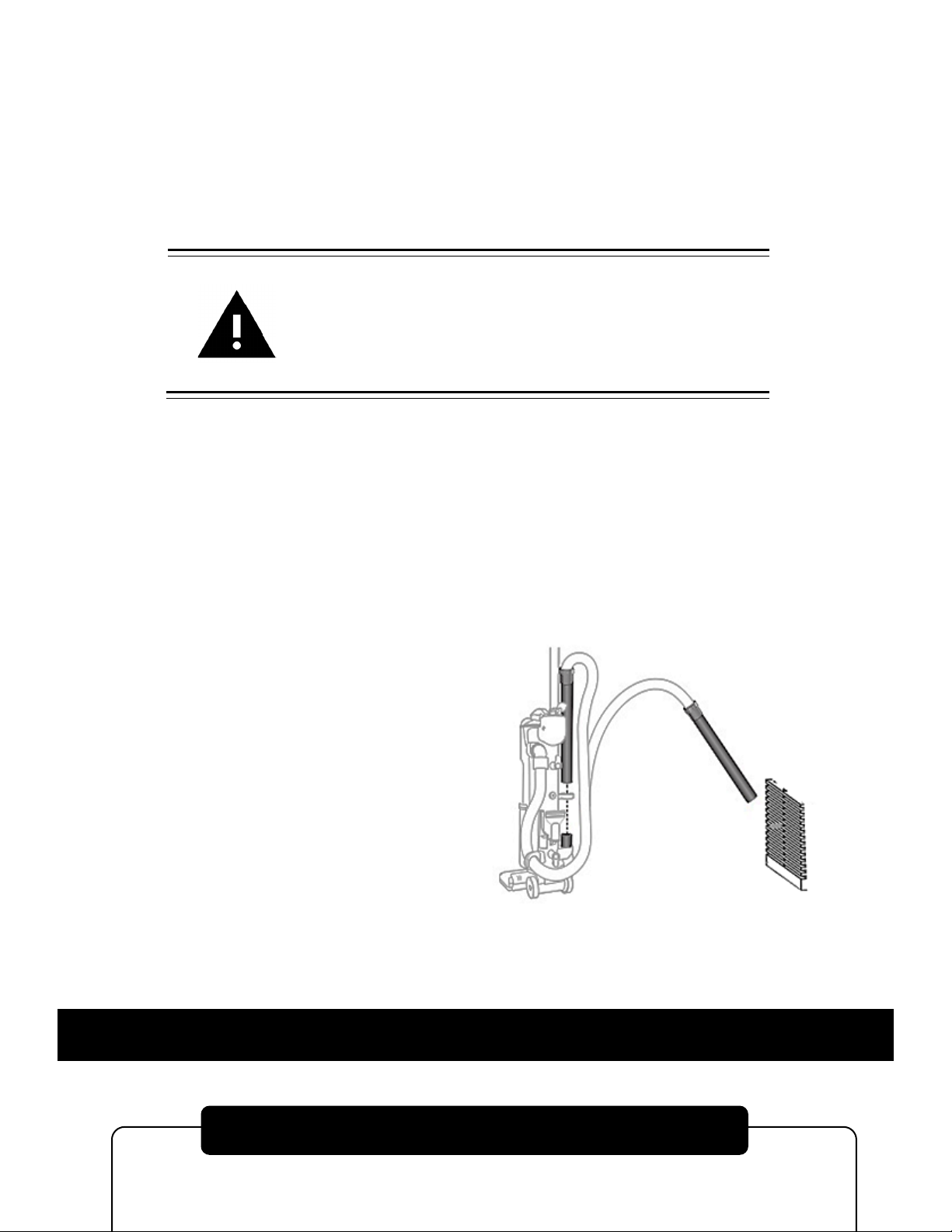
1. Unplug freezer from power supply.
2. Remove cover marked electrical panel located on side of cabinet.
3. Disconnect wires from battery terminals – Note which color wires were
connected to positive/negative. Colors vary depending on when unit was
made. Older models used black wire as positive and white as negative. Newer
models use red wire as positive and black as negative. See picture for battery
location.
4. Remove strap holding
battery in place.
5. Replace battery and
reconnect wires (see #3)
6. Test alarm.
7. Reinstall battery strap and
electrical box cover.
8. Plug freezer back into
power supply, and allow
up to 24 hours for the new
battery to fully charge.
4
CLEANING PROCEDURE
PREVENTATIVE MAINTENANCE

Wipe down the exterior of the freezer with a soft cloth and/or general spray
type polish. Do not use corrosive cleaners/chemicals on the exterior.
If frost builds up in the chamber, a bucket and ice-scraper can be used to
remove ice. If excessive ice builds up, the unit can be defrosted (see below).
1. Remove any product in the freezer, and temporarily store it in a
back-up freezer or elsewhere.
2. Unplug the freezer, and fully open the freezer front door / lid.
ATTENTION
FOR UPRIGHT UNITS, IT IS IMPORTANT TO PROTECT THE
CONTROL FROM DRIPPING WATER. PLACE A CLOTH OR
TOWEL ON THE LEADING EDGE OF THE COOLING
CHAMBER ABOVE THE CONTROL TO DEFLECT / ABSORB
WATER THAT COULD DRAIN ONTO THE CONTROL.
3. Air out the freezer, allowing the unit to reach room temperature for at
least 12 hours. Using fans to blow air into the unit is recommended.
4. Take a rag and wipe up all the excess water in the unit (melted frost).
5. Close the unit, and plug the unit in to activate the start-up process.
PLEASE CONSULT THE START-UP INSTRUCTIONS ON PAGE 1 FOR UNIT STARTUP
6. Once the desired temperature is reached, you may slowly begin to add
your product back into the unit.
ATTENTION
IT IS RECOMMENDED TO SLOWLY RE-ADD YOUR
PRODUCT INTO THE FREEZER TO PREVENT AN
EXTREME LOAD ON THE COMPRESSORS, WHICH
COULD SHORTEN FREEZER LIFE EXPECTANCY.
5
DEFROST PROCEDURE
CLEANING AIR CONDENSER
PREVENTATIVE MAINTENANCE
Large amounts of dust build-up on the air-cooled condenser can cause
excess stress for the refrigeration system. This excess stress may increase
the chance of a refrigeration issue and reduce the life expectancy of the
refrigeration system.
ATTENTION
IT IS RECOMMENDED TO CLEAN THE
CONDENSER AT LEAST ONCE EVERY
90 DAYS TO PREVENT DUST BUILDUP.
1. Using a Philips Head screwdriver, remove the screws for grill located on
front of unit. Once the screws are removed, the front grill can be removed
allowing easy access to the air cooled condenser.
Note: It is recommended to keep the screws in a safe location, so they can
be used to re-attach the grill once cleaning is completed.
2. Use a vacuum cleaner to pull up any dust built up on the condenser fins.
The most efficient method of doing this is using a furniture cleaning
attachment (if available).
Note: Cans of compressed air can also
be used to blow away dust, however
this is not the most recommended way
to clean the condenser; as the dust
may float through the air and
eventually return to clog up the
condenser.
3. Once clean, re-align the front grill and attach it using a screwdriver.
6
CHANGING SETPOINT TEMPERATURE
UNIT OPERATION
The temperature control is manually adjustable to the desired temperature in 1° C
increments within the limits of the control range.
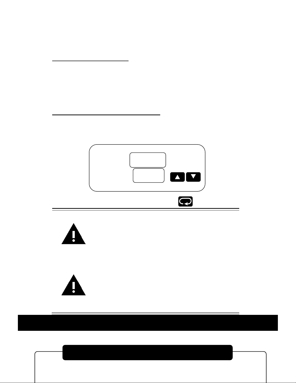
TEMPERATURE SET POINT
The control has two displays;
1) The upper display ( TEMP ) is the current actual unit temperature.
2) The lower display ( SET ) is the temperature set point.
The temperature set point has been pre-set at the factory. See page 1 for additional
information on factory default setpoint.
CHANGING TEMPERATURE SETPOINT
The temperature set point can be changed by simply pressing the “up” arrow to
raise or the “down” arrow to lower the temperature set point.
WARNING
CHANGING THE CONTROL PARAMETERS OUTSIDE OF
THE MANUFACTURE RECOMMENDED RANGE, COULD
SHORTEN THE LIFE-SPAN OF YOUR EQUIPMENT; OR
CAUSE ISSUES RESULTING IN MECHANICAL FAILURE.
WARNING
USE ONLY THE “UP” AND “DOWN” KEYS WHEN MAKING
CHANGES ON THIS CONTROL. WARRANTY WILL BE VOID
IF USED IN ANY OTHER WAY.
CONTACT FACTORY FOR ALL OTHER ADJUSTMENTS IN
SETTINGS.
7
TEMP
SET
-888
-888
ALARM SYSTEM
ALARM / RELAY OPERATION
When operating the unit for the first time, the alarm will be disabled until the
unit reaches set point, or 8 hours after the unit has been first plugged in.
The alarm will not sound again until the unit goes out of temperature range.
THE FACTORY DEFAULT ALARM RANGE IS ±12°C (20°F) FROM SETPOINT.
Note: The freezer contains a back-up battery, which will power the alarm
system for approximately 48 hours during a power outage.
ALARM SYSTEM BATTERY REPLACEMENT
•Rechargeable batteries should be changed approximately every three years
with lead acid rechargeable 1.2 Ah min, model PS-640F1 or equivalent.
Battery should be tested every 30 days.
ATTENTION
THE BATTERY DOES NOT POWER THE COOLING SYSTEM.
The dry contact relay is a terminal strip located on the back of the freezer.
RATING OF THIS CONNECTION:
2A 125 VAC
2A 30 VDC
RED – NORMALLY CLOSED
WHITE – COMMON
BLUE – NORMALLY OPEN
WARNING
IF IT IS NECESSARY TO REMOVE METAL COVER SCREEN
ON BACK OF FREEZER TO MAKE CONNECTIONS TO
ALARM RELAY, COVER MUST BE REPLACED BEFORE
FREEZER IS PUT INTO OPERATION
8
CONTROL KEYS & DISPLAYS
CONTROL PROGRAMMING
DRY CONTACT RELAY
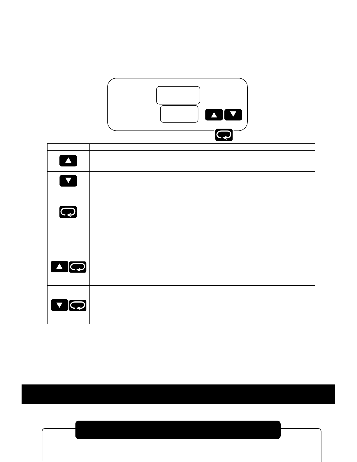
The FDC-4000 controller is programmed by using three keys on the front
panel. The available key functions are listed in following table. Note: Only use
the tip of your finger to depress the keys. Using a rigid object such as a pen,
screwdriver or even your finger-nail may permanently damage the keypad.
TOUCH KEYS
FUNCTION
DESCRIPTION
Up Key
Press and release to increase the control set-point (while in normal control
mode) or to change lower display program parameter (while in User Menu or
Factory Mode). Press and hold to accelerate increment speed.
Down Key
Press and release to decrease the control set-point (while in normal control
mode) or to change lower display program parameter (while in User Menu or
Factory Mode). Press and hold to accelerate decrement speed.
Pressing
key while in
normal control
mode
Scroll Key
Press and hold for at least 2 seconds and release (while in normal control
mode) to access operator level parameters. Press and release to cycle
through all user parameters. Press and hold for 2 seconds and release to
silence audible alarm under normal power or on battery power. While unit is in
an alarm condition, the external alarm relay contacts will remain energized
until the alarm condition no longer exists. Press and hold to display chamber
temperature while the controller is on battery power. Chamber temperature will
be displayed until key is released. Alarm contact will remain energized while
operating on battery power.
Press both keys
simultaneously
Current Power
Reading
Displays current AC power (i.e. 110VAC) as long as keys are pressed. If
power is 110VAC or 220VAC, unit will display 110. Mode is only active during
normal control mode (when top display = PV, Lower display = SP). N/A on
battery power.
Press both keys
simultaneously
Alarm Test
Energize audible alarm and alarm relay output as long as keys are pressed.
Mode is only active during normal control mode (when top display = PV,
Lower display = SP). N/A on battery power.
Note: When the controller is displaying temperature in normal control mode,
press/release or press/hold the up/down keys to change the set-point value.
This set-point mode does not apply to power off modes.
9
TEMP
SET
-888
-888
CONTROL DISPLAY VALUES
CONTROL PROGRAMMING

A
A
E
E
I
I
N
n
S
S
X
B
b
F
F
J
J
O
o
T
t
Y
y
C
C
G
G
K
Y
P
P
U
u
Z
C
c
H
H
L
L
Q
V
u
?
?
D
d
h
h
M
N
R
r
W
=
=
:Confused Character
The upper display is used to show the process value or menu prompt. The
lower display is used to show the set-point value or menu value. Both displays
are blank while on battery power unless the button is pressed to
display the process value. Note: When operating on battery power, the battery
status LED (labeled “BAT” on the front panel) will be lit.
To enter the USER parameter mode, hold the scroll key for 2 seconds and
release.
To enter the user parameter mode, hold the Scroll Button
for 2 seconds and release.
To make changes in the user parameter mode, press the up or
down arrows.
To exit the user parameter mode, press and release the Scroll
Button.
10
USER PARAMETER MODE
PROGRAM PARAMETER MODE
CONTROL PROGRAMMING
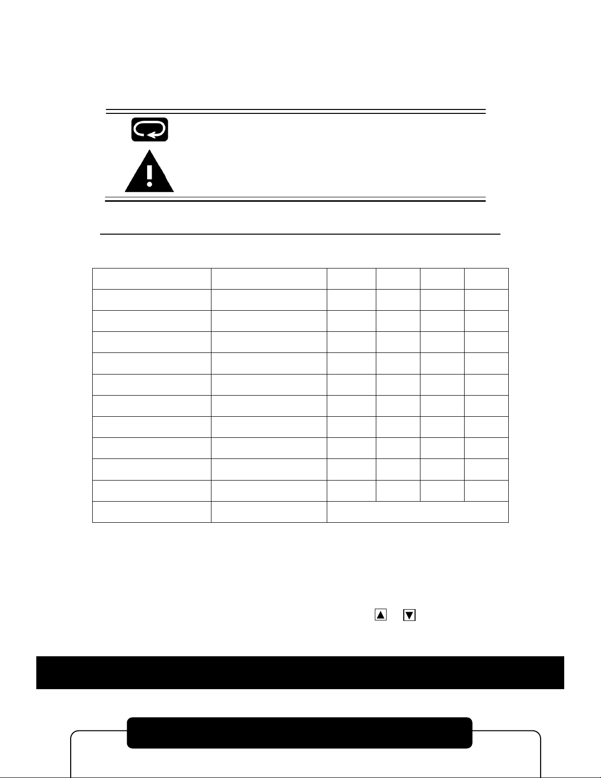
To enter the PROGRAM parameter mode, hold the scroll key until the screen
changes to ‘SPL’, then release. This will take approximately 15 seconds.
To page through Parameters; Press and Release the scroll key
Please read the superscript instructions (bottom of page) for
each Parameter value.
THE FOLLOWING VALUES WERE SET WHEN THIS UNIT WAS SHIPPED
PARAMETERS
DESCRIPTION °F °C ON OFF
SPL
3
Lower Setpoint -148 -100 X
SPH
3
Upper Setpoint -40 -40 X
Al
2
Alarm X
INV
1
Temperature Scale °F °C X
SHF
1
Calibration X
ASP
1
Alarm Differential 22 12 X
AHY
3,1
Alarm Hysteresis 1.8 1.0 X
OHY
3,1
Output Hysteresis 3.6 2.0 X
RB
1
Alarm Delay in Minutes 30 X
DoR
4
Door Alarm X
SP
2
Setpoint X
IN2
4
N / A N / A
TO EXIT TAP SCROLL KEY REPEATEDLY UNTIL TEMPERATURE/SETPOINT SCREEN
APPEARS
1) This parameter has been turned “on” by pressing either arrow key and then make your changes in
“user” mode.
THE VALUES TO BE CHANGED ARE DISPLAYED IN USER MODE ONLY, except SPL and SPH.
2) No values to change, either enable or disable by pressing the or arrow buttons.
3) Any changes made here without expressed permission from the manufacturer will VOID the
warranty of the unit.
4) The parameter “DoR” and IN2 cannot be utilized at this time.
11
CALIBRATION PROCEDURE
CONTROL PROGRAMMING

To calibrate the control, the calibration parameter must be turned on.
To enter the CALIBRATION mode, hold the scroll key until the screen changes
to ‘SPL’, then release. This will take approximately 15 seconds.
Press and Release the scroll key to page through Parameters.
Once value SHF is shown, Use the or arrow keys to change
value to ON.
PARAMETERS
DESCRIPTION °F °C ON OFF
SPL
3
Lower Setpoint
SPH
3
Upper Setpoint
Al
2
Alarm
INV
1
Temperature Scale
SHF
1
Calibration X
•Hold SCROLL KEY for 2 seconds and release. SHF should
appear in the top display and the current calibration value should
appear in the bottom display.
•The value can now be changed with UP or DOWN arrow keys.
•Once finished, press and release the SCROLL KEY to return to
the main screen.
12
ONCE THE CALIBRATION PARAMETER HAS BEEN TURNED ON
FREQUENTLY ASKED QUESITONS
COMMON QUESTIONS

Q: When should I defrost my unit?
A: Units should be defrosted when ice accumulation reaches approximately
1/2 inch thick. Ice acts like an insulator and has to work harder to reach the
same temperature.
Q: Is this unit self-defrosting?
A: No, this unit is a manual defrost unit.
Q: Should I leave my freezer operating when I am not using it?
A: This unit is designed to operate continuously. Leaving the refrigeration
system in operation, (even if not in use) may extend the life of the freezer,
and reduce the chance of refrigeration issues that may occur if the freezer is
not in operation for long periods of time.
Q: What ambient conditions is this unit designed for?
A: This unit is designed for:
•Indoor use
•Altitude up to 2000m.
•Temperatures 15°C to 32°C ( 60°F TO 85°F )
•Recommended humidity range of 30% to 90%.
Q: What electrical conditions is this unit designed for?
A: This unit is designed for:
•Mains supply fluctuations up to -5% to +10% of the nominal voltage.
Consult the serial tag for nominal voltage.
•Transient overvoltage typically present on the mains supply
(overvoltage category II). Pollution degree 1.
Q: Does my unit require a dedicated electrical line?
A: Yes, this unit requires a dedicated electrical line.
Please consult the labels on your unit for specific electrical requirements.
Q: Will the backup battery keep my unit cool during power failure?
A: NO, the backup battery only powers the alarm during power failure. It will
not power the refrigeration system, and will not keep the unit cooling during
power outages.
Q: Will the freezer start up after a power outage?
A: Yes, the freezer will automatically re-start when power is restored.
The overall restart process will begin in stages to prevent system overloads;
and may take up to minutes after re-start before cooling resumes.
13
COMPRESSOR MODEL
HP
VOLTAGE
HERTZ
PHASE
PART #
TECUMSEH AJB2433ZXA
1
115
50/60
1
AJB24-115
TECUMSEH AJB2433ZXD
1
208/220/230
50/60
1
AJB24-208
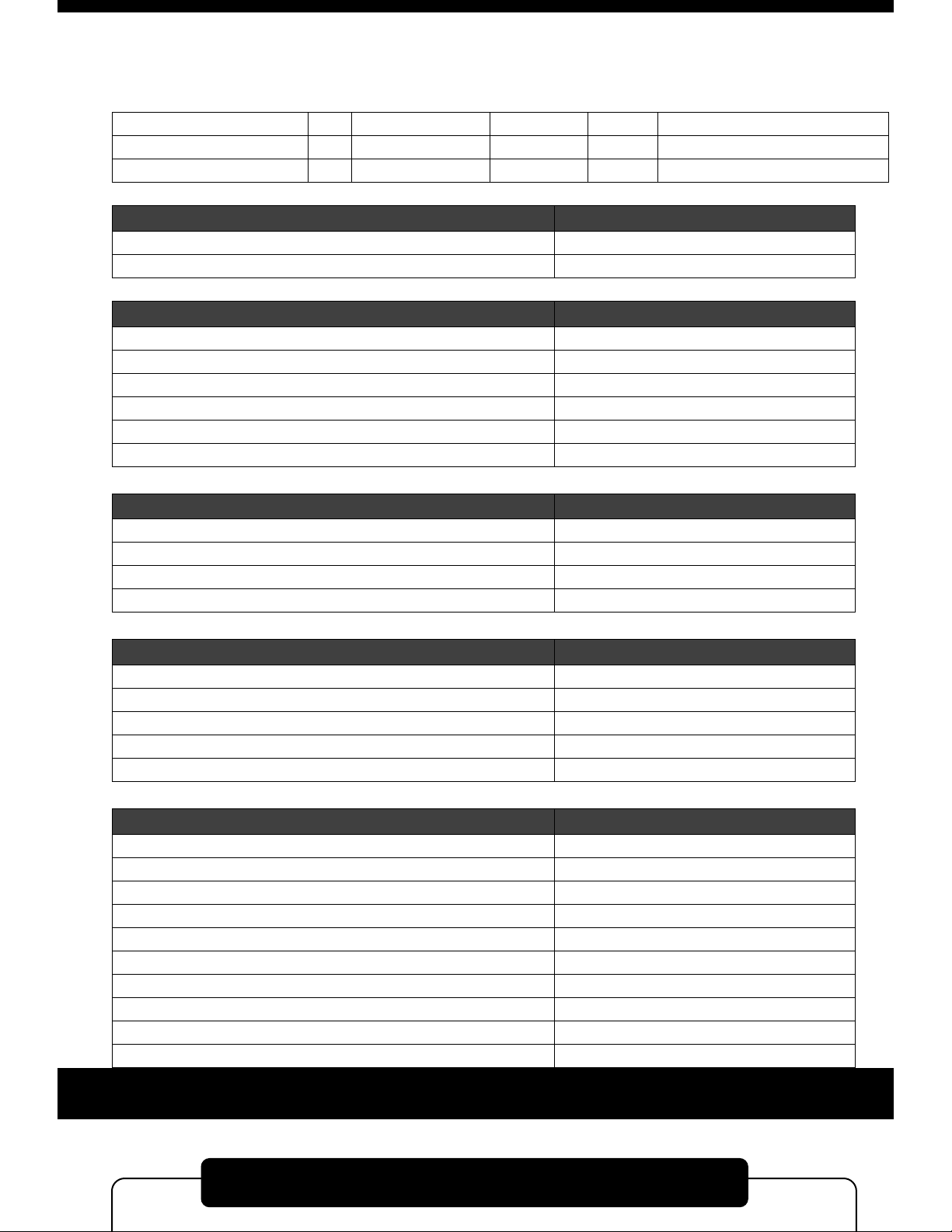
EMBRACO FFI12HBX
1/
3
115
50/60
1
FF12-115
DANFOSS SC15FTX
1/3
115
50/60
1
SC15-115
DANFOSS SC18FTX
1/2
208/220/230
50/60
1
SC15-208
TEMPERATURE CONTROL PARTS
PART #
FDC 4000
4000
FDC nCOMPASS
nCOMPASS
CASCADE ELECTRICAL PARTS
PART #
Heater Harness No. H-200
217-VOLTAGE
Refrigeration Switch No. 2X464
TOGGLE
Condenser Fan Motor No. GE-5411 - 115/60/1
500-115
Condenser Fan Motor No. GE-5421 - 230/50-60/1
500-VOLTAGE
Electrical Cord No. 8-3 (Please Specify Voltage)
PWRCRD-VOLTAGE
Control Board No. CECB2TUV (Please Specify Voltage)
231-VOLTAGE
REFRIGERATION HIGH STAGE PARTS
PART #
Air Cooled Condenser No. 3CZ0602B
254
Drier No. C-053-S
256H
Capillary Tube
HS-17, HS-20
Oil Separator, Temprite Series 900 (If Applicable)
900
REFRIGERATION LOW STAGE PARTS
PART #
Pressure Control No. 20PS01-0039
259
Receiver Condenser
RCN-LS
Drier No. CO-52S-S
256L
Capillary Tube
LS-28, LS-31
Oil Separator, Temprite Series 900 (If Applicable)
900
HARDWARE PARTS
PART #
Latch No. METL-L1-99
REX37L1-3
Chest Hinge
59-928M
Upright Hinge No. Polar 109-LH
59-928U
Cabinet Gasket
NX504B1
Lid or Door Gasket
PSOS
Grill No. 650H
356F, 356S
Sub-Lids (Must have Model Number)
SL-MODEL NUMBER
Inner Door (Must have Model & Serial Number)
357-MODEL NUMBER-SERIAL NUMBER
Clips & Rollers for Inner Doors (Quantity 10 minimum)
405
Shelves for Freezer (Must have Model Number)
4015-MODEL NUMBER
14
TECHNICAL ASSISTANCE
TECHNICAL SUPPORT

IN CASE OF REQUEST FOR REPAIR
If failure occurs, stop operation of unit, and turn OFF the breaker power
switch located in the electrical panel box, and unplug the power plug.
WARNING
IF FAILURE OCCURS AND UNIT IS STILL UNDER
WARRANTY, DO NOT ATTEMPT TO MAKE ANY REPAIR
MODIFICATIONS TO THE UNIT BEFORE CONTACTING
THE SO-LOW SERVICE DEPARTMENT, AS THIS MAY
RESULT IN WARRANTY BEING VOIDED.
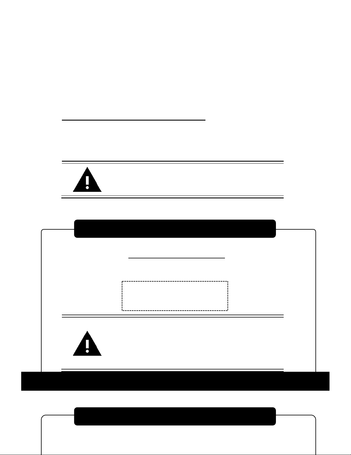
< CHECK FOLLOWING ITEMS BEFORE CALLING OR EMAILING >
◆Model Number of Product
______________________________________________
◆Serial Number of Product
______________________________________________
◆Issue (as detailed as possible)
______________________________________________________________________
________
______________________________________________________________________
________
______________________________________________________________________
________
______________________________________________________________________
________
So-Low Environmental Equipment Company
10310 Spartan Drive
Cincinnati, OH 45215-1221
For customer service:
Email: sales@so-low.com
For parts replacement:
Email: parts@so-low.com
For technical support:
Email: service@so-low.com

15
IT IS RECOMMENDED TO COMPLETE CHECKLIST EVERY 30 DAYS
◆MODEL NUMBER OF PRODUCT ◆SERIAL NUMBER OF PRODUCT
________________________________ ________________________________
Checked that freezer is operating at the correct setpoint temperature.
Checked operation of condenser fans, and cleaned air cooled condenser.
Confirmed unit is at least 6 inches away from walls, or obstacles, on all
sides to allow for sufficient air flow.
Confirmed ambient room temperature is within range acceptable ranges.
Recommended room temperature range is 15°C to 26°C ( 60°F TO 80°F )
◆ AMBIENT ROOM TEMPERATURE IS: _________________°
Checked operation of alarm system on unit.
Note: Alarm can be simulated by temporarily raising setpoint out of range.
Checked temperature recorders for proper operation (If applicable).
Note: If there are any deviations observed, further diagnosing may be required.
Check operation of CO2 or LN2 backup system. (If applicable)
ITEMS BELOW MUST BE CHECKED BY YOUR IN-HOUSE TECHNICAL PROFESSIONAL
USE CAUTION WHEN WORKING AROUND ELECTRICAL CIRCUITS
Checked AMP draw of unit when compressors stabilize.
Checked incoming voltage and voltage drop when compressors start up.
◆NOTES
______________________________________________________________________
________
______________________________________________________________________
________
◆COMPLETED BY ◆COMPLETED DATE
__________________________________ __________________________________
MAINTENANCE CHECKLIST
TECHNICAL SUPPORT
This manual suits for next models
3
Table of contents
Other SO-LOW Freezer manuals


