SO-LOW ABT-0720MB User manual

Part number 20077, Rev 0
1
GENERAL PURPOSE FREEZERS
ABT-0720MB ABT-1420MB, ABT-1720MB, ABT-2020MB,
ABT-2030MB, ABT-3020MB, ABT-3030MB, ABT-3020AB
OWNER’S INSTRUCTIONS
This manual describes how to operate and care for your appliance to get the best, most efficient, performance.
READ THIS BOOK!
Note to Customer: This merchandise was carefully packed and thoroughly inspected before leaving our plant.
Responsibility for its safe delivery was assumed by the carrier upon acceptance of the shipment. As directed on
the side of your packing carton, claims for loss or damage sustained in transit must be made on the carrier as
follows:
A.) Visible Loss, Damage, Shortage External Evidence of Loss or Damage: This type of damage must be noted on
the freight bill and acknowledged by the carrier’s agent (driver) at time of delivery. Make sure you get a signed
copy. Send a written request for an inspection to the carrier.
B.) Concealed Damage: This type of damage may not be discovered until the unit is being unpacked. When
concealed damage is discovered, stop unpacking immediately and contact the carrier immediately to report
the claim and request an inspection. This should be done as soon as possible and, in any case, must be done
within 15 days or receiving the merchandise. If at all possible, do not move the item and save all packaging
material for carrier’s inspection.
C.) FAILURE TO FOLLOW THESE INSTRUCTIONS MAY RESULT IN THE CARRIER REFUSING TO HONOR YOUR
COMPANY’S CLAIM. UNDER NO CIRCUMSTANCES SHOULD THE MERCHANDISE BE RETURNED TO THE
MANUFACTURER. NO RETURNS WILL BE ACCEPTED WITHOUT PRIOR AUTHORIZATION.
Horizon Scientific
125 Varnfield Drive
Summerville, SC 29483
Phone: 800-648-4041
Fax: 843-821-8051
Warranty:
Two-Year Parts and Labor
5 Years Compressor Parts
Revision Date:
08/27/2012

Part number 20077, Rev 0
2
TABLE OF CONTENTS
RECEIVING ............................................................................................................. 3
INSTALLATION........................................................................................................ 4
FREEZER OPERATION ............................................................................................. 6
DIGITAL MICROPROCESSOR TEMPERATURE CONTROLLER .................................... 7
QUICK TROUBLESHOOTING GUIDE ...................................................................... 10
MAINTENANCE AND CLEANING ........................................................................... 12
PRODUCT WARRANTY.......................................................................................... 14
BEFORE CALLING THE MANUFACTURER’S TECHNICAL SERVICE DEPARTMENT,
please have the unit’s model and serial number ready as well as the problem
description. The model and serial number is located on the serial tag which can
be found on the interior left upper wall of the unit.
For convenience, you may want to record the following information here for easy
access in the future.
Model number: __________________________________
Serial number: __________________________________
Date of delivery: _________________________________

Part number 20077, Rev 0
3
RECEIVING
Your unit was built, packaged, and inspected with extreme care. We shipped it to you using carriers we
trust with a proven track record of careful handling, good customer service, and on time delivery.
Unfortunately, regardless of all of these efforts sometimes accidents happen and occasionally those
accidents result in shipping damage. When the carrier picked up the merchandise from us, they
assumed responsibility for its condition en route to you. Thus, any claims for shipping damage must be
filed with the carrier. Like anybody else, carriers don’t like to pay out on insurance claims, so their claims
procedures and requirements are very restrictive. You should consult the carrier’s website for their
specific claims procedures. You should also know that time is of the essence.
There are two general types of shipping damage. The first is visible damage. This type of damage
includes visible loss, damage, shortage or any external evidence of loss or damage that is visible at time
of delivery. This type of damage must be noted in detail on your delivery receipt. Make sure the driver
signs and dates the delivery receipt, acknowledging the damage. This has to happen at the time of
delivery or it won’t happen at all. Keep a copy for your records and send another to the carrier’s damage
claims department along with a formal request for an inspection report. Follow up with a phone call.
Their contact information can be found on the carrier’s web site.
The second type of shipping damage is concealed damage. This type of damage will probably not be
apparent at time of delivery and may not be discovered until unpacking and inspecting the unit.
Remember, time is of the essence here. You should unpack and inspect the unit as soon as possible.
Each day that passes reduces the likelihood that the carrier will pay the claim. As soon as the concealed
damage is discovered, stop unpacking and retain all packing materials. Contact the carrier by phone to
report the claim. Note the date and time and person you spoke with. Get a claim number. Follow up
with a written letter referencing the claim number and including a formal request for an inspection.
Again, consult the carrier’s website for specific claim instructions and follow them precisely.
AS STATED ABOVE, THE CARRIER IS YOUR SOLE SOURCE FOR SATISFACTION OF A DAMAGE CLAIM.
UNDER NO CIRCUMSTANCES SHOULD THE MERCHANDISE BE RETURNED TO THE MANUFACTURER. NO
RETURNS WILL BE ACCEPTED WITHOUT PRIOR AUTHORIZATION.

Part number 20077, Rev 0
4
INSTALLATION
UNCRATING – Move the unit as close to the final location as
possible before unpacking. Remove the wooden planks or skid.
The location should be as close as possible to the power outlet.
This unit requires a minimum of 4 inches of air flow space in
back and 3 inches on the sides and top. Do not store material
on the top of this unit.
PLEASE NOTE! Your refrigerator or freezer is designed for
INDOOR USE and should be operated in an air conditioned
space with temperature between 65°F to 85°F. .
LEVELING −You can level your unit with the screw-type adjustable leveling legs on the front
corners of the unit. Turn counterclockwise to raise the corner; turn clockwise to lower it.
Leveling legs are required in front only. The unit may have a slight tilt from front to back
after legs are installed. This is acceptable and is recommended on this unit.
POWER SOURCE – The supply circuit to this cabinet
must conform to all National and Local Electrical
Codes. Consult the cabinet Serial-Data plate for
voltage, cycle, phase, and amp requirements before
making connection. VOLTAGE SHOULD NOT VARY
MORE THAN 5% FROM SERIAL PLATE RATINGS. A
separate circuit is recommended to prevent possible
loss of product due to over-loading or failure of other equipment on the same circuit.
PROTECT THE CIRCUIT WITH A 20 AMP DELAY-TYPE
FUSE OR CIRCUIT BREAKER. Do not use an extension
cord. Be sure your unit is properly grounded. Use the
3-prong plug provided into a 3-prong grounded outlet.
(Only this method complies with national electrical
codes, local codes and ordinances.) Unless the above
grounding method is followed, you are not protected
against severe or lethal shock in the event of a short
circuit of an electrical component or wiring of the unit.
STARTING – There are no compressor shipping bolts to
loosen or valves to open. All that is necessary after
the unit has been properly leveled is to plug the
service cord into an electrical outlet.When starting
this new appliance, allow the cabinet to operate a minimum of eight hours or until it has
started cycling normally before placing product in the cabinet. The motor compressor may
start and stop several times when the unit is first started or after defrosting, especially if the
weather is very hot. This is only normal functioning of the motor overload protector. The
motor compressor will cycle normally as soon as the excess heat has been removed.

Part number 20077, Rev 0
5
DOOR BINS (not applicable to all models)
Your unit may come equipped with storage bins in the door. Because of the temperature
characteriscs of these units, items stored in these bins may not be maintained in the desired
temperature band. Please restrict the use of these bins for non-crical temperature storage.
Adjustable Shelf Installaon (not applicable to all models)
Hook shelf clips onto pilaster strips (see Illustraon). Posion all four shelf clips equal in
distance from the floor for flat shelves. Wire shelves are oriented so that cross support bars are
facing down.
Place shelves on shelf clips making sure all corners are seated properly.
Temperature control
NOTE: The controls are preset at the factory to provide the desired air and product
temperatures inside of the units and require no further adjustment. Please contact the
manufacturer’s Technical Support Department before making any adjustments to determine
if adjustment is necessary and, if so, to make sure it is performed properly.
Some of the models are ordered and supplied with an electronic temperature control located
on the boom back of the unit near the compressor. Operaon of this controller is detailed in
the Digital Microprocessor Temperature Controller secon of this manual. All the other models
have a mechanical temperature control thermostat. Turning the thermostat towards the higher
numbers will make the unit colder. Lower numbers make it warmer. Turning the thermostat to
the offor 0 posion will turn the freezer off.

Part number 20077, Rev 0
6
FREEZER OPERATION
After the unit is properly installed and power is applied, it will take some time before the
system is cooled down to temperature and cycling normally. You should wait 8 hours on the
first startup before beginning to add product to the unit. This ensures that the unit is installed
and operating properly before being put into service. After this wait time, the unit should be
cycling in the desired temperature band. The units are calibrated before leaving the factory, so
no adjustment should be necessary.
Loading the units will again cause temperature to rise as the warmer product is introduced into
the compartment. If a large amount of product is to be introduced, it is a good idea to do it in
stages, allowing several hours between stages to allow temperature to stabilize again before
introducing additional warm product. This will minimize the temperature transient while
loading. Other tips for successful loading include:
-Leave about 2-3 inches of free space along the back and sides of the unit to allow for proper
air flow and, therefore, more even cooling of the product.
-Do not overload the unit. Maximum suggested load is about 75% of the chamber capacity.
Additionally, the load should be distributed evenly from top to bottom and side to side for
best results.
-Minimize the time the door is open. On top of letting the cold air out, you are also letting
warm, moist air in which can result in more condensation and/or frost in the unit.
Model ABT-3020AB has an auto-defrost feature. Every 6 hours, it will go into a defrost cycle to
remove frost build-up. During this cycle, which can last up to 25 minutes, the compressor is
turned off and defrost heaters are turned on in the evaporator section. This will cause a
temperature transient which will be seen in air temperature inside the unit but should not
significantly affect product temperatures.
Remember that the units are calibrated to the desired temperature band before leaving the
factory. We also do extensive testing to ensure that these temperatures will result in product
temperatures in the desired band. There should be no need to adjust the temperature control
on these units, but if it is necessary, they can be adjusted using the temperature control
instructions on the previous page.
It is STRONGLY RECOMMENDED that you contact the manufacturer’s Technical Support
Department prior to performing any temperature adjustments to ensure the adjustment is
necessary and, if so, it is performed correctly.

Part number 20077, Rev 0
7
DIGITAL MICROPROCESSOR TEMPERATURE CONTROLLER - ABT-2030MB and
ABT-3030MB only
Product Description
The digital microprocessor temperature controller is designed to provide on/off control of
refrigerators or freezers. The controller also provides a constant readout of the air temperature
inside of the unit. A touch keypad allows the user to easily select the display units, set point,
differential set point, and heating or cooling mode.
Please Note: The digital temperature controller has been factory set and tested
to allow your unit to operate at its desired temperature cycle. Adjusting the
settings on the controller will alter these factory settings. WE STRONGLY
RECOMMEND YOU CONTACT THE MANUFACTURER’S TECHNICAL SUPPORT
DEPARTMENT BEFORE MAKING ANY ADJUSTMENTS TO THIS CONTROLLER.
Part number 20077, Rev 0
8
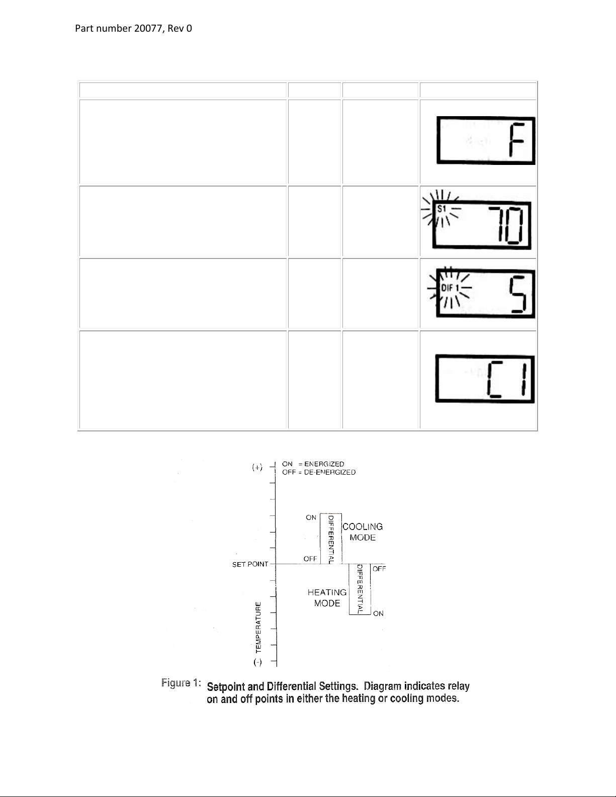
Programming
Procedure
Display
Description
Display
To start programming, press the SET
key once to access the Fahrenheit /
Celsius mode. The display shows the
current status,
Ffor Fahrenheit or C
for Celsius. Press up or down arrow to
toggle between the For C.
For C
Fahrenheit or
Celsius Scale
Press SET key again to access the
set point mode. The LCD will display
the current set point and S1 will be
blinking. Press the up and down keys
to adjust to the desired setting.
S1
(blinking)
Setpoint
Temperature
Press SET key again to access the
differential mode. The LCD will display
the current differential and
DIF1 will
be blinking. Press the up and down
keys to adjust to the desired setting.
DIF 1
(blinking)
Differential
Temperature
Press SET key again to access the
cooling or heating mode. The LCD
displays the current mode,
C1 for
cooling or
H1 for heating. Press up or
down key to toggle between
C1 or H1
.
Press the
SET key again.
Programming is complete.
C1 / H1 Cooling or
Heating
mode

Part number 20077, Rev 0
9
Error Messages
Display
Messages
Corrective Action
E1
Appears when either the up or down
key is pressed when not in the
programming mode
If the E1 message appears even when
no keys are being pressed, replace
control.
E2
Appears if the control
settings are not
properly stored in memory.
Check all settings and correct if
necessary.
EP
Appears when the probe is open,
shorted or sensing a temperature that
is out of range.
Check to see if the sensed
temperature is out of range. If not,
check fo
r probe damage by comparing
it to a known ambient temperature
between
-
30°F and 220°F. Replace the
probe if necessary.
EE
Appears if the EPROM data has
been corrupted.
This condition cannot be field repaired.
Replace the control.
CL
Appears if
calibration mode has been
entered.
Remove power to the control for at
least five seconds. Reapply power. If
the CL message still appeared, replace
the control.

Part number 20077, Rev 0
10
QUICK TROUBLESHOOTING GUIDE
Check these items before calling for service
PROBLEM:
POSSIBLE CAUSE / SOULTIONS:
Unit does not run
•
Electrical circuit is not 110-120V 60Hz.
•The power cord is not plugged in.
•No power at electrical outlet. Check to make sure
breaker is not tripped or fuse is not blown. Additionally,
make sure unit is not plugged into a Ground Fault Circuit
Interrupter (GFCI) type of outlet.
Unit does not maintain at the
proper temperature
•Check the room temperature. We recommend the
refrigerator or freezer should be placed in the air
conditioned room between 65°F to 85°F. If the room
temp is too warm, the refrigerator or freezer may not be
able to maintain the interior temp at proper range.
•Door is not closed properly.
•Amount of stored product is overloaded.
•Product replacements are pushed against rear wall or
interrupted the proper refrigerator air circulation. For
the proper air circulation, place the products evenly on
each shelf. Do not push against the refrigerator’s rear or
side walls.
•Evaporator is blocked by frost or ice. Remove the
products, unplug the refrigerator or freezer power, and
allow the unit to defrost. If the problem still exists, call
for service.
•3rd party thermometer is placed incorrectly. For proper
temperature monitoring, the thermometer should be
place in the middle of refrigerator.
PLEASE NOTE! Prior to shipment, each refrigerator and freezer
has been calibrated and tested at proper temperature range.
Appliance runs too long
•Prolong door openings.
•Control set too cold.
•Room temperature is high which will make the unit work
harder to keep cool.
Temperature of external wall
surface is warm
•The exterior walls can be as much as 30 degrees warmer
than room temperature due to the embedded
condenser coils. This is normal when the unit is
operating.

Part number 20077, Rev 0
11
PROBLEM:
POSSIBLE CAUSE / SOULTIONS:
Compressor noises
•Compressor may be overheated. Please check the room
temp and ensure the range is within 65°F to 85°F. If the
problem still exists, call for service.
Moisture collects inside
•Door gasket is not sealing properly. Check for debris,
cracks, and items passing through door at the gasket.
•The freezer is facing a doorway or is underneath of air
conditioning vent. Relocate the unit or redirect air vent.
•Too many door openings. Minimize time door is open.
•Hot, humid weather increases condensation.
•Make sure there is a water trap (U-shaped loop) in the
drain tube near the compressor. This will “trap” a small
amount of water in the loop and prevent air from
entering the chamber through the tube.
Moisture collects on outside
surface
•Hot, humid weather increases condensation.
•As humidity decreases, moisture will disappear.
Odor inside the unit
•
Interior needs to be cleaned. See section on
maintenance and cleaning in this manual.
•Make sure product containers are tightly sealed to
prevent leakage
Door will not close
•The unit is not level. Refer to the Leveling section at the
beginning of this manual
•Check for dirt and debris or items passing through the
door seal.
MOISTURE DURING THE SUMMER SEASON
The amount of moisture, condensation, or high humidity related issues increase during the summer
and, in most cases, will self-resolve when the weather cools down. Please note a refrigeration
system will NOT generate moisture or water but simply condenses the moisture that is already in
the chamber. Keeping the unit in an air conditioned, low humidity space will resolve many issues.
Other things you should check
1. Location of the freezer (See Quick Troubleshooting Guide above)
2. Door sealing and frequency of door opening event (See Quick Troubleshooting Guide above)
3. Make sure there is a water trap (U-shaped loop) in the drain tube near the end. This will
“trap” a small amount of water in the loop and prevent air from entering the chamber
through the tube.
Before calling the manufacturer’s Technical Support Department, please have the unit’s model
and serial number ready as well as the problem description. The model and serial number is
located on the serial tag which can be found on the interior left upper wall of the unit.

12
MAINTENANCE AND CLEANING
Manual-Defrost Freezers (All models except auto defrost) should be defrosted whenever ¼ to ½ inch
of frost has accumulated. Use the procedures in the defrosng secon starng at the boom of this
page for best results. They should also be cleaned periodically. Use the cleaning agents and suggesons
in the table below for best results.
CLEANING
PART CLEANING AGENTS TIPS AND PRECAUTIONS
Interior and Door
Liners
Soap and water
Baking soda and water
Use 2 tablespoons of baking soda in 1 quart of
warm water
Be sure to wring excess water out of sponge or
cloth before cleaning around controls, light bulb
or any electrical parts.
Door Gaskets
Soap and water
Wipe gaskets and their seang surfaces with a
clean socloth
Shelves Soap and water Do not wash removable shelves in dishwasher
Exterior and
Handles
Soap and water
Non Abrasive Glass
Cleaner
Do not use commercial household cleaners,
ammonia, or alcohol to clean handles
Use a so cloth to clean smooth handles
Do not use a dry cloth to clean smooth handles
Manual Defrosng
It is important to defrost and clean the freezer when ¼ to ½ inch of frost has accumulated. Frost
may tend to accumulate faster on upper part of the freezer due to warm, moist air entering the
freezer when the door is opened. Between defrost evoluons; you can minimize frost build-up
by using a plasc scraper to remove frost. Scrape with a pulling moon. Never use a metal
instrument to remove frost. Never use a damp cloth or wet hands as they will sck to the inside
surfaces when cold. When defrosng becomes necessary, disconnect freezer from power

Part number 20077, Rev 0
13
source by unplugging to avoid electrical hazard. DO NOT ADJUST THE THERMOSTAT. Remove
the product and leave the door open while defrosting the freezer.
Remove the drain plug on the inside floor of the
freezer by pulling straight out. To access the external
drain tube on models with a base panel, first remove
the two screws from the base panel. Locate the drain
tube near the left center under the freezer. Place a
shallow pan under the drain tube. Defrost water will
drain out. Check the pan occasionally to ensure it does
not overflow. A ½ inch garden hose adaptor (available
at most hardware stores) can be used to drain the
freezer directly into a floor drain. Replace the drain
plug when defrosting is complete so warm air does not
enter the freezer through the hole.
Defrosting tips – If the frost is soft, remove it with a plastic scraper. If the frost is glazed and
hard, fill deep pans with hot water and place them inside on the freezer bottom. Close the
freezer door. Frost should soften in about 15 minutes. Repeat this procedure as necessary until
all frost is removed.
After defrosting - replace the drain plugs (if applicable) and remove any towels, tools, or pans
from the interior of the freezer. Clean the interior and exterior of the unit using the cleaning
suggestions on the previous page. Plug the unit back in and restore it to service per the
operation section of this manual.
This manual suits for next models
7
Table of contents
Other SO-LOW Freezer manuals


