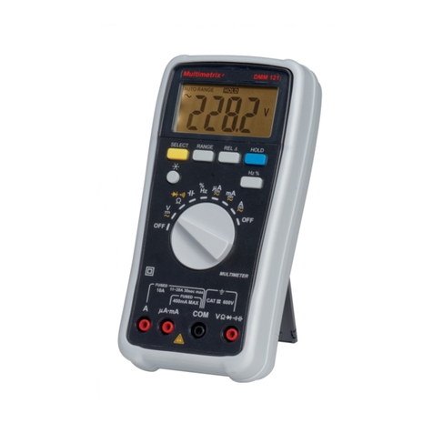
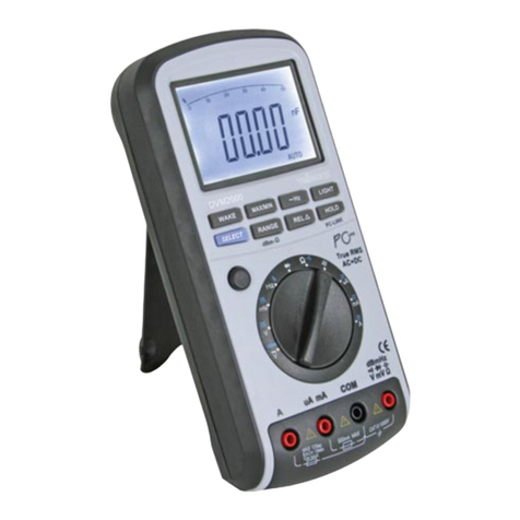
Socket & See ENGINEER DMM User manual

Instruction Manual & Specification
SAS095v1
ENGINEER DMM
6000 count, true RMS
digital multimeter

1. Safety
1.1 Equipment Markings / Symbols
1.2 Operational Safety
The ENGINEER DMM is designed to be used by skilled persons in accordance with safe
methods of work. If the ENGINEER DMM is used in a manner not specified by Socket &
See, the protection provided by it may be impaired.
Inspect the product before each use. If any damage is visible; such as cracks in the
casing, damage to any accessories, leads or probes, the unit should not be used.
This tester has been designed to be used with suitable PPE, including insulated gloves if
required.
To avoid electric shock do not touch the connections / measuring points to be measured.
When in use always grip the test probes behind the finger guards.
Caution - refer to the instruction manual
Danger of electric shock
Construction is double insulated
Product should be recycled as electronic waste
Conforms to EU standards
Measurement Category III is applicable to test and measuring circuits
connected after the source of the building’s low-voltage MAINS
installation. This part of the installation is expected to have a
minimum of two levels of over-current protective devices between
the transformer and connecting points of the measuring circuit.
Examples of CAT III are measurements on devices installed after the
main fuse or circuit breaker fixed within the building installation. Such
as distribution boards, switches and socket outlets.
This tester’s voltage rating for a CAT III location is 1000 Volts where the voltage
is Phase (Line) to Earth.
CAT III
1000V

Do not operate the ENGINEER DMM with the battery cover off as this will compromise the
insulated safety barrier. Do not use the tester in unfavourable environments such as:
●Wet conditions or in high humidity
●Dust and flammable gasses, vapours or solvent
●Thunderstorms or similar conditions such as electrostatic fields
2. Description
The ENGINEER DMM is a 6000 count, True RMS Digital Multimeter featuring non contact
voltage detection, temperature measurement and back lit LCD. Other functions include
resistance, diode test, continuity check, capacitance and frequency.
2.1 Contents
●Digital Multimeter
●Test Leads
●9v (DF22 / 6LR61 / 1604) battery (fitted)
●K type temperature Ni-Cr and Ni-Si sensor, temperature range measurable -40°C to
250°C
●Operating Manual
2.2 Features
●True RMS
●6000 Count
●Digit 3 3/4
●Auto / Manual V (AC / DC) 1000V
●µA / mA / 10A (AC / DC) 6000µA / 600mA / 10A
●AC / DC external clamp adaptor 600A, 1 mV = 1A
●Auto / Manual V(AC) with Hz / % selectable
●AC Current with Hz / % selectable
●Auto / Manual Ω up to 60 MΩ
●Continuity (<50Ω Beep)
●Capacitance 10nF - 100mF
●Diode check (3.0V)
●10 MΩ Input Impedance
●NCV Non Contact AC voltage detection (audible and visual) >100V
●NCF Non Contact Frequency 45 - 75 Hz (50 - 500 VAC)
●Freeze / Hold Reading
●Auto Power Off (5 mins)
●Relative Reading (REL)
●Frequency / Duty Cycle (Hz / %) (9.999Hz - 55.00KHz / 0.1 - 99.9%)
●Temperature measurement -40°C to 1000°C
●K Type thermocouple (-40°C to 250°C)

2.3 Indication
REL/∆ Adjust reading to zero Capacitor
Alternating Current (AC) nF / µF Nanofarad / Microfarad
Direct Current (DC) mF Millifarad
mV Millivolt Hz/kHz/MHz Hertz / Kilohertz / Megahertz
V Volt % Duty cycle
mA Milliampere AUTO Auto range / Measurement
µA Microampere CAT IV Overvoltage category 4
A Ampere CAT III Overvoltage category 3
Negative Ground Potential
Signal strength of NCV Over range
HFreeze / Hold reading Non Contact Voltage
ΩOhm NCV function display active
KΩKilohms Celsius / Fahrenheit
MΩ Megaohms Low battery display
Diode test Reading Recorded
Continuity Non-contact frequency
NCV
NCV
NCF
°C/F°
MAX/MIN
MAX-MIN

1. NCV / NCF sensor
2. LC Display
3. Backlight / NCV detection LED
4. Range button (press once) Manual decimal point mode for voltage, resistance and
current measuring.
5. Select button (press once).
a) V range: DCV / ACV / Hz% / NCF
b) Ohm range: Ohm / diode/ continuity / capacitance
c) Current (µA / mA / 10A) range: AC / DC
d) Wake up at auto power off mode
e) Continuous operation / data logging
f) NCV / Temp
6. MAX / MIN / MAX-MIN button (press once) For recorded voltage, current, resistance
and temp reading.
7. REL (relative reading) button (press once) Adjust reading to zero, except NCV range.
8. Hold / button (press once)
a) Hold / Freeze the reading except NCV range
b) Press >3 seconds to ON / OFF backlight
9. Hz / % button (press once) toggle between frequency and duty cycle
10. Rotary switch
11. Unfused test leads
12. Test Lead holder
13. Battery Cover
14. Folding stand
15. Fuse Holder a)600mA 1000V Fast acting b)10A 1000V Fast acting
14
13
12
1
2
9
11
7
3
10
8
5
4
15a
15b
6

3 Usage
Do not exceed the maximum input values. Extreme caution should be used when
voltages higher than 25 VAC or 35 VDC could be present.
When testing is complete, turn the rotary dial to the off position.
To wake the tester from Auto Power Off (APO) mode press the select button >3 seconds.
3.1 Voltage
Turn the rotary dial to the voltage position. Ensure the test leads are connected to the
correct meter terminals. Use the select button to toggle between VAC and VDC as
required. Connect the two test probes to the object / circuit to be measured. The
measured value is then displayed on the LC display.
When measuring VDC the red probe indicates the positive pole and the black probe the
negative pole. If a minus is displayed on the LC display the measured voltage is negative
polarity.
3.2. Non Contact Frequency (NCF) 50/60Hz
Turn the rotary dial to the voltage AC position. Press the Hz / % button, Hz will be shown on
the LC display. Insert the red test lead into the positive terminal of the meter. Now move
the NCV / NCF sensor towards the socket / cable to be tested. The measured value will
be indicated on the LC display.
3.3 Resistance
Ensure that the component to be measured is safely isolated from any voltage source.
Turn the rotary switch to the resistance setting. Ensure that the test leads are connected to
the correct meter terminals. Check the test leads for continuity by touching the probe tips
together. The value must be approximately 000.0Ω. If the reading is not zero press REL to
adjust to zero. Connect the probes across the object to be measured ensuring a good
clean contact, as long as the object to be measured is not high resistance or interrupted
the measured value will be displayed on the display. If OL is displayed the measuring
range has been exceeded or the measuring circuit has been interrupted.
3.4 Diode Test
Ensure that the diode to be measured is safely isolated from any voltage source. Turn the
rotary switch to the diode setting. Ensure that the test leads are connected to the correct
meter terminals. Connect the test probes to the diode to be tested. The display shows the
forward voltage. If OL is displayed the diode may be being measured in the reverse
direction or it may be faulty.
3.5 Continuity check
Ensure that the component to be measured is safely isolated from any voltage source.
Turn the rotary switch to the continuity setting and press the select button. Ensure that the
test leads are connected to the correct meter terminals. Check the test leads for

continuity by touching the probe tips together. The value must be approximately <0.5Ω. If
the reading is not zero press REL to adjust to zero. Connect the probes across the object
to be measured ensuring a good clean contact. The LC display will show the
measurement in Ohms and an audible tone will sound if the circuit is less than 50 ohms.
3.6 Capacitance
Ensure that the capacitor to be measured is safely isolated from any voltage source. Turn
the rotary switch to the capacitance setting. Press select until the LC display will show
either nF / µF / mF. When showing nF, if the display is higher than 0.000 nF press the REL
button to zero. Ensure the test leads are connected to the correct meter terminals.
Connect the probes across the capacitor to be measured ensuring a good clean
contact. The LC display will show the results.
3.7 Current
Current measurement is possible in three ranges µA , mA or 10A. All ranges have fused
protection to prevent overload. Turn the rotary switch to the current range required.
Ensure the test leads are connected to the correct meter terminals for the range selected.
Press the select button to choose AC or DC as required. Connect the test probes in series
with the circuit to be measured. The display will indicate polarity along with the
measurement.
Never measure >600 mA on the µA / mA range or >10A on the 10A range as this will cause
the fuse to blow. The voltage in the circuit being measured must not exceed 1000V AC or
DC.
3.8 Non Contact Voltage (VAC)
Turn the rotary switch to NCV range. The LC display will display EF and NCV icon. Hold the
meter and move the NCV sensor near to the live power source. On detection of an AC
source the red LED will blink, an audible tone sounds and the bar graph on the LC display
indicates the signal strength.
3.9 Temperature
Turn the rotary switch to Temp and press the select button to chose °C or °F. Insert the K
type leads into the correct meter terminals. Make a good contact between the K type tip
and the object to be measured. Allow at least 30 seconds before taking the reading.
3.10 Frequency
Select the Hz/% button to toggle between frequency and duty cycle. Results will be
displayed on the LC display.

4. Maintenance and Service
4.1 Battery Replacement
Ensure the meter is disconnected from all live sources. Remove test leads and
switch the tester off. Lift the tester stand and unscrew the battery cover screws.
Lift the battery cover taking care to retain the screws. Replace the 9V battery
ensuring correct polarity. Secure the battery cover with the two screws.
4.2 Fuse Replacement
Ensure the meter is disconnected from all live sources. Remove test leads and
switch the tester off. Remove the tester rubber over mould. Unscrew the fuse
holder screws and lift the fuse carrier. Replace fuses as required, refit the fuse
carrier and secure with the screws. Fit rubber over mould.
4.2 Trouble Shooting
If required, clean with a damp cloth and mild detergent. Do not use abrasives
or solvents.
With the exception of the batteries and fuses there are no user serviceable
parts.
Contact Socket & See for parts and technical assistance.
Socket & See
Century Road
High Carr Business Park
Newcastle
Staffordshire
ST5 7UG
UK
Tel: +44 (0) 1782 567096
Fax: +44 (0) 1782 567095
Email: [email protected]
Website: www.socketandsee.co.uk
Error Possible cause
The meter does not function Check the battery status
No measuring value change Check correct function is selected
Reading on the display hangs up Turn the rotary switch to OFF and
switch on again after 3 seconds
Fatal error or undefined reading Turn the rotary switch to OFF and
switch on again after 3 seconds

5. Specification
AC Voltage manual range
Range
Resolution
Accuracy
600.0mV 000.1mV +0.6% +3
digits
6.000V 0.001V +0.6% +3
digits
60.00V 00.01V +0.6% +3
digits
6000.0V 000.1V +1.0% +3
digits
1000V 1V +1.0% +3
digits
DC Voltage manual range
Range
Resolution
Accuracy
600.0mV 000.1mV +0.6% +2
digits
6.000V 0.001V +0.6% +2
digits
60.00V 00.01V +0.6% +2
digits
6000.0V 000.1V +1.0% +2
digits
1000V 1V +1.0% +2
digits
AC Current µA manual range
Range Resolution Accuracy
600.0µA 000.1µA +0.15% +5
digits
6000µA 1µA +0.15% +5
digits
DC Current µA manual range
Range Resolution Accuracy
600.0µA 000.1µA +0.12% +3
digits
6000µA 1µA +0.12% +3
digits
AC Current mA manual range
Range Resolution Accuracy
60.00mA 00.01mA +0.15% +5
digits
600.0mA 000.1mA +0.15% +5
digits
DC Current mA manual range
Range Resolution Accuracy
60.00mA 00.01mA +0.15% +5
digits
600.0mA 000.1mA +0.15% +5
digits
AC Current 10A manual range
Range Resolution Accuracy
6.000A 0.001A +1.5% +5
digits
10.00A 00.01A +1.5% +5
digits
DC Current 10A manual range
Range Resolution Accuracy
6.000A 0.001A +1.5% +5
digits
10.00A 00.01A +1.5% +5
digits
Continuity
Range Resolution Accuracy
600.0Ω000.1Ω+0.8% +6 digits
Audible sound when
< 50Ω (approx) 0.001Ω+0.8% +6 digits

Frequency for Electrical (Auto range)
sensitivity 1.0V rms
Range Resolution Accuracy
9.999Hz -
55.00KHz
0.001Hz -
0.01KHz
+0.15% +3
digits
Diode
Range Resolution Accuracy
3.000V 0.001V +10% +5
digits
Non-Contact AC Voltage detect
LC Displays EF
and NCV
When >100 VAC LED blinks
faster and buzzer sounds
AC / DC external clamp adaptor input
Range Resolution Accuracy
600A @ 1mV / 1A 0.1A +0.8% +5 digits
Note: Accuracy does not include clamp meter error.
Resistance manual range
Range
Resolution
Accuracy
600.0Ω000.1Ω+0.7% +5
digits
6.000KΩ0.001KΩ+0.6% + 2
digits
60.00KΩ00.01KΩ+0.6% +2
digits
600.0KΩ000.1KΩ+0.7% +2
digits
6.000MΩ0.001MΩ+1.5% +5
digits
60.00MΩ00.01MΩ+2.5% +6
digits
Capacitance Auto range
Range Resolution Accuracy
9.999nF 0.001nF +5% +7 digits
9.999µF 0.001µF +5% +5 digits
99.99µF 0.01µF +10% +10 digits
9.999mF 0.001mF +10% +10 digits
99.99mF 0.01mF +10% +10 digits
Duty Cycle
Range Resolution Accuracy
0.1 - 99.9% 0.1% +1.2% +2 digits
Non-contact Frequency (NCF) detection
Range Resolution Accuracy
45Hz - 70Hz (50 -
500 VAC) 0.01Hz +2Hz

Temperature measurement
Range
Resolution
Accuracy
-40°C to 1000°C -40°C to 0°C 1°C + (3% + 5°C)
1°C to 250°C + (2% + 2°C)
-40°F to 1832°F -40°F to 32°F 1°F + (3% + 5°F)
33.8°F to 482°F + (2% + 2°F)
Note: K type thermocouple probe (Ni-Cr and Ni-Si) is only applicable for the
measurement of temperature range -40°C to 250°C. Accuracy does not include
Type K thermocouple error.
General Specification
Power Supply 1 x 9V (6F22 / 6LR61 / 1604) battery
Low battery Indication 2.6 V appox
Overvoltage category CAT III 1000V (CAT IV 600V)
Operating Temperature 0 - 40ºC
Storage Temperature -10 to 60ºC
Operating Humidity 80% @ 31ºC to 50% @ 40ºC
Safety Compliance BSEN 61010-2-030:2010
EMC Compliance BSEN 61326-2-2:2013
Test Leads Dual insulated
Ceramic Fuses
1000V, F,600mA (Ø6x32mm)
1000V, F, 10A (Ø10x38mm)
Probes GS38 Compliant
Dimensions (mm) 188 x 96 x 56
Weight (g) 415 Without battery

Ordering Information
SOC/ENGINEERDMM TRMS Digital Multimeter
SOC/TECC6 Soft Carry Case
SOC/DLMPROLEAD 3 Wire Non-Fused Distribution Board
Test Lead Set
SOC/DLMPRO Combined DMM, Loop and Socket
Tester
SOC/PDLPRO High Resolution Loop Tester
SOC/IRCPRO Insulation and Continuity Tester
SOC/IRCCHECK Calibration Checkbox
SOC/CB400 Non Trip Installation Testing
Calibration Checkbox
SOC/VIP150 Craftsman Voltage Tester
SOC/SP400 Proving Unit
SOC/VVDPRO Vibrating Non Contact AC Voltage
Detector
SOC/LOD10 Locking Off Device
SOC/TECC2 Soft Carry Case
tel 01782 567096 | fax 01782 567095
see everything at socketandsee.co.uk
Socket & See, Unit 4, Century Road, High Carr Business Park, Newcastle-Under-Lyme, Staffordshire, ST5 7UG, UK
Socket & See is a trading division of UK Test Instruments Ltd.
Table of contents
