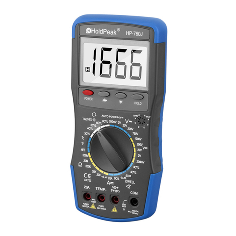
TekPower DT9602R User manual

Model DT9602R
6000 COUNT AUTO RANGE & AUTO POWER OFF DIGITAL MULTIMETER
OPERATION MANUAL
This LCD Auto Range & Auto Power off digital multimeter is a portable, compact ,
6000 COUNT digits with bargraph multimeter . It is ideally suited for field , lab , shop,
car,andhomeapplications.
S
afety Information
Warning
To avoid possible electric shock or personal injury, follow these guidelines:
●Do not use the meter if it is damaged. Before you use the meter, inspect the case. Look for
cracks or missing plastic. Pay particular attention to the insulation surrounding the
connectors.
●Inspect the test leads for damaged insulation or exposed metal. Check the test leads for
continuity. Replace damaged test leads before you use the meter.
●The RESPONSIBLE BODY shall be made aware that, if the equipment is used in a manner
not specified by the manufacturer, the protection provided by the equipment may be impaired.
●Do not use the meter if it operates abnormally. Protection may be impaired. When in doubt,
have the meter serviced.
●Do not operate the meter around explosive gas, vapor, or dust.
●Do not apply more than the rated voltage, as marked on the meter, between terminals or
between any terminal and earth ground.
●Before use, verify the meter’s operation by measuring a known voltage.
●When measuring current, turn off circuit power before connecting the meter in the circuit.
Remember to place the meter in series with the circuit.
●When servicing the meter, use only specified replacement parts.
●Use caution when working above 30 V ac rms, 42 V peak, or 60 V dc. Such voltages pose a
shock hazard.
●The finger or any part of your body shall not be beyond the barrier of the test probe
when measuring.
●Avoid working alone.
●When using the probes, keep your fingers behind the finger guards on the probes.
●Connect the common test lead before you connect the live test lead. When you disconnect
test leads, disconnect the live test lead first.
●Remove test leads from the meter before you open the battery door.
●Do not operate the meter with the battery door or portions of the cover removed or loosened.
●To avoid false readings, which could lead to possible electric shock or personal injury,
replace the batteries as soon as the low battery indicator (
) appears.
●Use only One standard 9 volt battery (NEDA 1604, IEC 6F22 or equivalent), properly installed
in the meter case, to power the meter.
●To avoid the potential for fire or electrical shock, do not connect the thermocouples to
electrically live circuits.
Caution
To avoid possible damage to the meter or to the equipment under test, follow these guidelines:
●Disconnect circuit power and discharge all high-voltage capacitors before testing resistance,
continuity, diodes, or capacitance.
●Use the proper terminals, function, and range for your measurements.
●Before measuring current, check the meter’s fuses and turn power OFF to the circuit before
connecting the meter to the circuit.
1

Safety Symbols
Symbols used on the meter and in this manual are explained as below:
International Electrical and Relative Symbols
AC (Alternating Current) Important information
DC (Direct Current) Caution risk of electric shock
European Safety Standard Earth ground
Double insulated Low Battery Indicator
The symbol indicating separate
collection for electrical and
electronic equipment. US Safety Standard.
1. SPECIFICATIONS
1.1 GENERAL SPECIFICATIONS
Display : 6000 Count LCD with 62 segments bargraph display, max. reading is
6000.
Range control : Auto range / Manual range control
Polarity : Automatic negative polarity indication.
Zero adjustment : Automatic.
Overrange indication
: The "OL" display.
Lowbattery : The " " is display when the battery voltage is below 7.5V approx.
Auto Power Off : 15 minutes after stopping the switch, or no any operation for the press
button, the meter automatically enters to power off mode.
Safety standards : ETL / EMC/LVD. The meter is up to the standards of IEC1010
Pollution Degree 2, Overvoltage CategoryⅡ.
Operating environment: Temperature 32 to104°F (0°C to 40°C), humidity< 80% RH.
Storage environment :Temperature -4 to140°F (-20°C to 60°C), humidity< 90%RH.
Power: One standard 9 volt battery (NEDA 1604 IEC, 6F22 or equivalent)
Dimension: 98(W)×177(H)×39(D) mm
Weight : Approx. 300g (including battery).
1.2 ELECTRICAL SPECIFICATIONS
Accuracy is ± (% of reading + number in last digit) at 23 ± 5°C , <75% RH.
DC Voltage
600mV, 6V, 60V, 600V
:±(0.5%+5)
1000V : ± (0.8% +5)
Impedance : 10MΩ
Overload protect: 1000V DC or AC 750V RMS.
AC Voltage (True RMS)
6V, 60V, 600V
:±(0.8%+5)
750V
:±(1.2%+5)
Impedance : 10MΩ.
Frequency response :50~400Hz
Overload protect: 1000V DC or AC 750V RMS.
Resistance
600Ω, 6kΩ, 60kΩ, 600KΩ :± (1% +5)
6MΩ, 60MΩ
:± (2% +5)
2

Overload protection
: 250V DC/AC RMS.
DC Current
600µA, 6000µA
:±(2.0%+5)
60mA, 600mA
:±(1.5%+5)
6A,10A :±(2%+5)
Overload protect:Fast fuse 0.8A/250V & Fast fuse 10A/250V.
10A for 15sec each 15min maximum.
Input voltage drop ≤:0.3V.
Note: Not to measure a current in a circuit with voltage more than 250V.
AC Current (True RMS)
600µA, 6000µA
:±(2.5%+5)
60mA, 600mA : ± (2% +5)
6A,10A
: ± (2.5% +5)
Overload protect:Fast fuse 0.8A/250V & Fast fuse 10A/250V.
10A for 15sec each 15min maximum.
Input voltage drop ≤:0.3V.
Frequency Respond: 50Hz - 400Hz
Note: Not to measure a current in a circuit with voltage more than 250V.
Capacitance
40nF : ± (5% +10)
400nF, 4μF, 40μF :±(3%+5)
400μF, 4000μF
:±(20%+5)
Overload protection
: 250V DC/AC RMS.
Frequency
9.999Hz -10MHz :±(0.1%rdg+5)
Sensitivity: ≤100kHz:1.5V RMS; >100kHz: 5V RMS
Overload protect: 250V RMS
Duty Cycle
0.1~99.9% :±(2%rdg+5)
Overload Protection :250V DC/AC RMS..
Temperature
32°F -- 104°F / 0°C--+40°C
: ±5°F / ±3°C (Use build-in temperature sensor)
-50℃-200℃:±1.5%±3℃
-58℉-392℉:±1.5%±5℉
200℃-700℃
:±2%±3℃
392℉-1292℉
:±2%±5℉
Overload protection : 250V DC/AC RMS
Diode Test
Test current :1±0.6mA Test voltage :Approx. 2.8V
Overload protection : 250V DC/AC RMS
Continuity Test
Audible indication: less than 120ΩApprox.
Overload protection : 250V DC/AC RMS.
2. OPERATION
WARNING
1) When measuring voltage ensure that instrument is not connected or switched to resistance
range. Always ensure that the correct terminals are used for the type of measurement to be
made.
3

2) Use extreme care when measuring voltage above 50V, especially from sources where high
energy is existed.
3) Avoid making connections to "live" circuits whenever possible.
4) When making current measurements ensure that the circuit not "live" before opening it in order
to connect the test leads.
5) Before making resistance measurements or diode test, ensure that the circuit under test is
de -- energized.
6) Always ensure that the correct function and range is selected. If in doubt about the correct
range to use, start with the highest and work downwards.
7) Extreme care should be taken when using the instrument to conjunction with a current
transformer connected to the terminals if an open circuit occurs.
8) Ensure that the test leads and probes are in good condition with no damage to the insulation.
9) Take care not to exceed the over-load limits as given in the specifications.
10) Before opening the case of the instrument to replace battery or fuse, disconnect the test leads
from any external circuit, set the selector switch to "OFF" position.
2.1Function Press Button
1) SELECT (State choice)
There are several functions at one rotary switch position, press SELECT button to select
function you want, It allowable to select AC or DC current, Resistance or Diode, Audible
continuity , capacitance measurement, ℃or temperature measurement℉.
2) RANGE (Range selection)
When power on, meter at auto range mode, press RANGE button you can select measurement
range you want. Range is run up with times of pressing RANGE button until its max, then return
the min range. Press RANGE button more than 2 seconds , the meter return to auto range. This
button do not effect on frequency, duty cycle, capacitance, diode & continuity test and
temperature measurement.
3) (Relative Measurement / RS232 enable)
Press this button the meter enter relative measuring state and “Δ” symbol appear on LCD.
The result of the relative measurement is the difference between measuring value and
reference value. The reference value is produced same as momentary reading value when
pressing this button, press it again to exit this state and “Δ” symbol disappear on display, and
this button do not effect on frequency, diode and continuity test function. Press this button less
than 2 seconds the meter enter relative measuring state and “Δ” symbol appear on LCD. The
secondary function of button is RS232 communication enable and disable. If you
press it more than 2 seconds, the RS232 will be started and press it more than 2 seconds again
will cancel RS232 communication.
4) (Data Hold / Backlight)
Press this button less than 2 seconds the meter enter data hold mode and “ HOLD ” symbol
appear on LCD, and the momentary value while pressing the button display on LCD. Press it
again to exit this mode and “ HOLD ” symbol disappear on display. As data hold function,
this button do not effect on diode and continuity test function. The secondary function of
button is backlight enable and disable. If you press it more than 2 seconds, the backlight will be
turn on and press it more than 2 seconds again will make the backlight off.
5) Hz/DUTY (Frequency and Duty Cycle measurement switch button)
When you make frequency, AC voltage or AC current measurement, press this button to
switch Hz or duty cycle test mode.
6) MAX/MIN (Maximum value / Minimum value)
Press MAX/MIN button the meter enter Maximum value / Minimum value record mode and
“ MAX ” / ” MIN ” symbol appear on LCD, the LCD will display the maximum value or minimum
value science pressing the button always. Press MAX/MIN more than 2 seconds button again to
4

exit this mode and “ MAX ” / ” MIN ” symbol disappear on display. This button do not effect on
diode and continuity test function, capacitance measurement, frequency measurement.
2.2 Check the 9-volt battery.
If the battery is weak, a “ " symbol will appear on the left of the display. It means that the
battery should be replaced.
2.3 DC and AC Voltage measurement
1)Connect the black test lead to "COM" socket and red test leads to the "VOLT" socket.
2)Set the selector switch to “ VOLT DC ” or “ VOLT AC” position to select DCV or ACV measuring
mode.
3)Connect the probes across the source or load under measurement.
2.4 DC and AC Current measurement
1)Connect the black test lead to "COM" socket and red test leads to the " µA/ mA" socket.
2)For measurement up to 600mA. Set the selector switch to “AC/DC µA ” or “AC/DC mA ”
position and press SELECT button to select DC or AC current measuring mode.
3)For current measurement from 600mA to 10A, connect the red test lead to "10A" socket. Set
selector switch to “AC/DC 10A ” position and press SELECT button to select DC or ACA
measuring mode.
4)Connect the probes across the source or load under measurement.
Note: Not to measure a current in a circuit with voltage more than 250V.
2.5 Resistance measurement
1) Connect the black test lead to "COM" socket and red test leads to the " Ohm " socket.
2) Set the selector switch to " Ohm / / / / CAP " position, and press SELECT button to
select resistance measuring mode.
3) Connect the probes across circuit to be tested.
Caution: Ensure that the circuit to be tested is "dead".
Max. input over-load: 250V RMS. and<10sec.
2.6 Diode, continuity test
1) Connect the black test lead to "COM" socket and red test leads to the " / " socket.
2) Set the selector switch to " Ohm / / / CAP " position and press SELECT button
to select Diode or continuity test mode.
3) Connect the black and red test probe to the cathode (-) and anode (+) ends of diode to be
testedrespectively.
4) Read the forward voltage drop (junction) value from the display. If reverse connected the
probes to diode, display shows over-load.
5) In Continuity test, the beeper sounds continuously if the resistance is less then
120 Ωapproximately.
Caution: Ensure that the circuit to be tested is "dead".
Max. input over-load: 250V RMS. and<10sec.
2.7 Capacitance measurement
1) Before testing, discharge the capacitor by shorting its leads together. Use caution in handing
capacitors because they may have a charge on them of considerable power before
discharging.
2) Connect the black test lead to "COM" socket and red test leads to the " CAP " socket.
3) Set the selector switch to " Ohm / / / CAP " position and press SELECT button
to select capacitance measuring mode.
5

4) Press “
∆
” button, you can use the relative function to eliminate the zero error.
5) Connect the probes across capacitor to be tested.
Note: When testing 400μF / 4000μF capacitor, note that there will be approx. 30 sec time lag.
Caution: Ensure that the circuit to be tested is "dead".
Max. input over-load: 250V RMS. and<10sec.
2.8 Frequency measurement
1) Connect the black test lead to "COM" socket and red test leads to the " FREQ " socket.
2) Set the selector switch to “DUTY FREQ” position.
3) Connect the probes across the source or load under measurement.
2.9 Temperature measurement
1) Set the selector switch to the ” TEMP °C/°F” range and connect the k type thermocouple’s
black ( or “-“ terminal ) test lead to “COM” socket and red ( or “+“ terminal ) test lead to the
"TEMP " socket and read value on display screen. The range of TP-02 thermocouple is
-50~+700°C ( -58 ~1292°F).
2) Press SELECT button to switch °C or °F display.
3) Opening the input will display the temperature at the meter terminals by the internal built-in
sensor.
2.10 Auto Power Off
When the meter has been turned on about 15 minutes without any action from the users, the
meter will automatically change to “OFF” mode, and you can press any function button to
wake up again. If press and hold SELECT button to turn on the meter, the AUTO POWER
OFF function will be canceled.
2.11 Using Communications
1) Connecting the RS232 cable to the meter and a computer as shown in Figure 1, then turn on
the meter.
2) Press button more than 2 seconds on the panel to start the RS232 communication
function. If you want to cancel the RS232 function, please press the button more than
2 seconds once again.
3) About the father information of communication, please refer to the on-line help of Data Logger
attached.
3.CARE AND MAINTENANCE
Figure 1. RS232 Communication
6

3.1 CARING FOR YOUR MULTIMETER
Your Digital MultiMate is an example of superior design and craftsmanship. The following
suggestions will help you care for the multimeter so you can enjoy it for years.
1) Keep the multimeter dry. If it gets wet, wipe it dry immediately. Liquids can contain minerals that
can corrode electronic circuits.
2) Use and store the multimeter only in normal temperature environments. Temperature extremes
can shorten the life of electronic devices, damage batteries, and distort or melt plastic parts.
3) Handle the multimeter gently and carefully. Dropping it can damage the circuit boards and case
and can cause the multimeter to work improperly although the holster can provide enough
protection.
4) Keep the multimeter away from dust and dirt, which can cause premature wear of parts.
5) Wipe the multimeter with a damp cloth occasionally to keep it looking new. Do not use harsh
chemicals, cleaning solvents, or strong detergents to clean the multimeter.
6) Use only fresh batteries of the required size and type. Always remove old or weak batteries. They
can leak chemicals that destroy electronic circuits.
3.2 MAINTENANCE
9-Volt battery replacement or fuse replacement
WARNING
TO AVOID ELECTRIC SHOCK,REMOVE TEST LEADS BEFORE OPENING CASE
AND BATTERY DOOR.
a) Ensure the instrument is not connected to any external circuit. Set the selector switch to
“OFF“position and remove the test leads from the terminals.
b) Remove the screw on the battery case and lift the battery case. Remove the spent battery and
replace it with a battery of the same type.
Pull up the box case
Battery: One standard 9
volt battery (NEDA 1604,
IEC 6F22 or equivalent)
Battery Replacement
c) Do not dispose the batteries with the household waste. Refer to your local area for the proper
disposal of used batteries.
d) Remove the screws on the bottom case and lift the case. Replace only with the same type and
rating of fuse F2 0.8A/250V FAST or F1 10A/250V FAST.
7

Scre
w
Fuse:
0.8A/250V FAST
Fuse:
10A/250V FAST
Fuse Re
p
lacement
9602RCk507-2
8
Table of contents
Other TekPower Multimeter manuals
