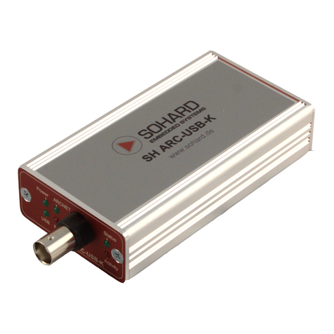
SOHARD SH ARC-66 User manual

Manual
SH ARC-66
ISA ARCNET card with COM90C66
Version 0 .00

SH ARC-66 Version 0 .00
Inhaltsverzeichnis
1. Introduction ..........................................................................................
2. Compatibility.........................................................................................
. Ports and Displays................................................................................4
.1 Coax.................................................................................................4
.2 Twisted Pair.....................................................................................4
. Node ID............................................................................................5
.4 Selection of Interfaces.....................................................................6
.5 Bus Termination...............................................................................6
.6 Red LED...........................................................................................7
.7 Green LED.......................................................................................7
.8 I/O Base Address.............................................................................8
.9 Memory Address..............................................................................8
.10 Interrupt..........................................................................................9
.11 Boot ROM....................................................................................10
4. Memory address space......................................................................10
5. Factory Settings..................................................................................11
6. Technical Data....................................................................................11
6.1 General..........................................................................................11
6.2 Coax Interface................................................................................11
6. TWP Interface................................................................................11
7. CE Declaration of Conformity ...........................................................12
8. Restriction of Hazardous Substances Directive (RoHS)...................1
9. Support...............................................................................................1
9.1 Contacts.........................................................................................1
10. Literature...........................................................................................1
11. Warranty...........................................................................................1
Page 2

SH ARC-66 Version 0 .00
1. Introduction
The SH ARC-66 is a 16 bit ARCNET card for computers with an ISA
bus. The card is conceived for the use in computers for office
communications as well as in industrial computers. Both alternatively
available interfaces, coax and TWP, ensure a maximum of flexibility.
By means of the attached software drivers, the card can be integrated
into your application fast and at moderate costs.
For the implementation in office communication systems, the standard
ARCNET driver of the corresponding operating system can be used.
2. Compatibility
The card is software-compatible to 8 bit ARCNET cards (with COM
90xx). Thus the SH ARC-66 can easily be used as a substitute for an
older ARCNET card. Having connected the card, it behaves like its 8 bit
predecessor. The card can only be switched into the 16 bit modus (see
[1]) by setting a further bit specifically – usually, this is already effected
by the 16 bit driver.
By activating the internal termination, the SH ARC-66 behaves like a
"star card" (low-impedance bus interface).
Page

SH ARC-66 Version 0 .00
3. Ports and Displays
3.1 Coax
Situated at the mounting bracket of the card, the coaxial port is provided
by a BNC-socket.
3.2 Twisted Pair
Two RJ45 sockets at the mounting bracket of the card represent it’s
TWP ports. Both sockets are completely equal. If the card is operated as
a bus card, the incoming line must be put into one of the RJ45 sockets
and the outgoing line into the other RJ45 socket. Only a RJ45 socket is
used in the star operation. The free socket remains free and the card is
terminated internally or an external termination (bus termination) is put
onto the free socket.
Page 4

SH ARC-66 Version 0 .00
Pin Bezeichnung
1 n.c.
2 n.c.
n.c.
4 Pulse 1
5 Pulse 2
6 n.c.
7 n.c.
8 n.c.
3.3 Node ID
Every ARCNET node within the network needs a ‘Node ID’, which is
assigned once – also called node number or station address. This is
adjusted by means of a DIP switch at the mounting bracket of the card.
The Node ID arises (see table) in accordance with the binary coding,
being apparent by the position of the eight switches included in the DIP
switch S1 (ON=0 / OFF=1).
Node ID 1 2 3 5 6 7 8
1 OFF ON ON ON ON ON ON ON
2 ON OFF ON ON ON ON ON ON
OFF OFF ON ON ON ON ON ON
4 ON ON OFF ON ON ON ON ON
5 OFF ON OFF ON ON ON ON ON
6 ON OFF OFF ON ON ON ON ON
7 OFF OFF OFF ON ON ON ON ON
8 ON ON ON OFF ON ON ON ON
9 OFF ON ON OFF ON ON ON ON
10 ON OFF ON OFF ON ON ON ON
11 OFF OFF ON OFF ON ON ON ON
12 ON ON OFF OFF ON ON ON ON
1 OFF ON OFF OFF ON ON ON ON
14 ON OFF OFF OFF ON ON ON ON
15 OFF OFF OFF OFF ON ON ON ON
16 ON ON ON ON OFF ON ON ON
...
254 ON OFF OFF OFF OFF OFF OFF OFF
255 OFF OFF OFF OFF OFF OFF OFF OFF
Page 5

SH ARC-66 Version 0 .00
The Node ID = 0, which is not permitted, has an additional feature. If all
the DIP switches are set to “ON”, the Node ID can be adjusted by the
software. Therefore, the card does not become active on part of the
network unless an initialization was carried out by the software.
3.4 Selection of Interfaces
There are two interfaces on the card which cannot be used
simultaneously so that a selection by means of jumpers is necessary.
The coax port is selected by setting the jumpers like the ones in the left
picture. The TWP port is selected by setting the jumpers like the ones in
the right picture.
Please also note the various terminations in the following chapter.
3.5 Bus Termination
Every network line must be terminated. If the SH ARC-66 forms the end
of a line, it has to be terminated there.
There are two ways of termination:
●externally: here the line termination is attached externally (as BNC
terminators).
●Internally: The card offers the possibility of internal termination.
The corresponding jumper on the card has to be set as shown
below.
We recommend the external termination. In both cases termination has
to be carried out according to the characteristic impedance of the cable
used (e.g. RG62=9 ohm)
Page 6

SH ARC-66 Version 0 .00
The internal jumper for the termination offers the possibility of
terminating with 9 ohm (left picture above) or with 120 ohm (right
picture above).
Type of cable Wellenwiderstand
coax 9 ohm
twisted pair e.g. 120 ohm
3. Red LED
The red LED will be active if the SH ARC-66 is accessed by the ISA bus.
These accesses become visible by prolonging the impulse lenght.
Status of the LED Description
Active Access to SH ARC-66
Dark There is no access (chip select) to the SH ARC-66
3.7 Green LED
The green LED indicates activities on the ARCNET bus.
Status of the LED Description
Active Network OK (Token revolves)
Flashing (short
“blinding out” 1sec)
Network tries to re-configure itself (reconfiguration).
However, no other node is found.
Dark Card does not have any supply voltage or
Node ID = 0 and card is not initialized
Page 7

SH ARC-66 Version 0 .00
3.8 I/O Base Address
The I/O base address of the ARCNET controller is set by means of a
DIP switch (S2) on the card. Switch position “ON” represents a low level
and switch position “OFF” represents a high level on the signal line.
The I/O base address must be still unused in the system.
I/O Base Address IOS0 IOS1 IOS2
0x260-0x26F ON ON ON
0x290-0x29F OFF ON ON
0x2E0-0x2EF ON OFF ON
0x2F0-0x2FF OFF OFF ON
0x 00-0x 0F ON ON OFF
0x 50-0x 5F OFF ON OFF
0x 80-0x 8F ON OFF OFF
0x E0-0x EF OFF OFF OFF
3.9 Memory Address
The Memory address of the ARCNET controller (Dual Ported RAM) is
set by means of a DIP switch (S2) on the card. Switch position ON
represents a low level and switch position OFF represents a high level
on the signal line.
The switch position also defines which memory area the boot ROM
superimposes..
The memory areas must be still unused in the system.
Page 8

SH ARC-66 Version 0 .00
MS0 MS1 MS2 MS3 MS ARCNET RAM BOOT ROM
ON ON ON ON ON C:0000-C:07FF C:2000-C: FFF
OFF ON ON ON ON C:0800-C:0FFF C:2000-C: FFF
ON OFF ON ON ON C:1000:-C:17FF C:2000-C: FFF
OFF OFF ON ON ON C:1800-C:1FFF C:2000-C: FFF
ON ON OFF ON ON C:4000-C:47FF C:6000-C:7FFF
OFF ON OFF ON ON C:4800-C:4FFF C:6000-C:7FFF
ON OFF OFF ON ON C:5000-C:57FF C:6000-C:7FFF
OFF OFF OFF ON ON C:5800-C:5FFF C:6000-C:7FFF
ON ON ON OFF ON C:C000-C:C7FF C:E000-C:FFFF
OFF ON ON OFF ON C:C800-C:CFFF C:E000-C:FFFF
ON OFF ON OFF ON C:D000-C:D7FF C:E000-C:FFFF
OFF OFF ON OFF ON C:D800-C:DFFF C:E000-C:FFFF
ON ON OFF OFF ON D:0000-D:07FF D:2000-D: FFF
OFF ON OFF OFF ON D:0800-D:0FFF D:2000-D: FFF
ON OFF OFF OFF ON D:1000-D:17FF D:2000-D: FFF
OFF OFF OFF OFF ON D:1800-D:1FFF D:2000-D: FFF
ON ON ON ON OFF D:4000-D:47FF D:6000-D:7FFF
OFF ON ON ON OFF D:4800-D:4FFF D:6000-D:7FFF
ON OFF ON ON OFF D:5000-D:5700 D:6000-D:7FFF
OFF OFF ON ON OFF D:5800-D:5FFF D:6000-D:7FFF
ON ON OFF ON OFF D:8000-D:87FF D:A000-D:BFFF
OFF ON OFF ON OFF D:8800-D:8FFF D:A000-D:BFFF
ON OFF OFF ON OFF D:9000-D:9700 D:A000-D:BFFF
OFF OFF OFF ON OFF D:9800-D:9FFF D:A000-D:BFFF
ON ON ON OFF OFF D:C000-D:C7FF D:E000-D:FFFF
OFF ON ON OFF OFF D:C800-D:CFFF D:E000-D:FFFF
ON OFF ON OFF OFF D:D000-D:D7FF D:E000-D:FFFF
OFF OFF ON OFF OFF D:D800-D:DFFF D:E000-D:FFFF
ON ON OFF OFF OFF E:0000-E:07FF E:2000-E: FFF
OFF ON OFF OFF OFF E:0800-E:0FFF E:2000-E: FFF
ON OFF OFF OFF OFF E:1000-E:17FF E:2000-E: FFF
OFF OFF OFF OFF OFF E:1800-E:1FFF E:2000-E: FFF
3.10 Interrupt
The interrupt, which shall be triggered by the card, can be selected with
the jumper panels JP1 and JP2.
The selected interrupt must not be occupied within the system and must
be assigned to the ISA bus by the motherboard BIOS.
Page 9

SH ARC-66 Version 0 .00
3.11 Boot ROM
The card can be equipped with a boot ROM (socket IC4). Therefore it is
possible to boot the computer via the network.
The jumper “ENROM” has to be plugged in. However, we recommend to
plug in the jumper even if no boot ROM is used.
The selected memory area of the boot ROM can be taken from the table
of chapter .8 "memory address."
. Memory address space
The ARCNET controller superimposes at 16 addresses in the I/O area
and occupies 2 kilobytes of the main memory (Memory) (see [1]).
IO-base address + Read register Write register
0 STATUS INTERRUPT MASK
1 DIAG. Status COMMAND
2 CONFIGURATION CONFIGURATION
I/O SELECT RESERVED
4 MEMORY SELECT RESERVED
5 NODE ID NODE ID
6 RESERVED RESERVED
7 RESERVED EXTERNAL REGISTER
8 RESET RESET
9 RESET RESET
A RESET RESET
B RESET RESET
C DATA LOW DATA LOW
D DATA HIGH DATA HIGH
E ADDRESS PTR LOW ADDRESS PTR LOW
F ADDRESS PTR HIGH ADDRESS PTR HIGH
Page 10

SH ARC-66 Version 0 .00
5. Factory Settings
The SH ARC-66 is delivered with the following configuration.
Interface Coax
Internal Termination Not connected (OFF)
Node ID
I/O base address 0x2E0
Memory area D:0000-D:07FF
Interrupt 10
ENROM Connected (ON)
6. Technical Data
.1 General
Compatibility: ANSI/ATA 878.1
Power consumption: < 4W
Operating temperature range: 0°C bis +55°C
Storage temperature range: -20°C bis +85°C
Dimensions without connectors: width 121 mm, height 21 mm,
depth 129 mm
Weight: max. 0.5 kg packed for shipping
.2 Coax Interface
Datenrate: 2.5Mbps
Input impedance: ≥ 10 kΩ (at f = 5 MHz)
Output voltage: min. 16 Vss with 9 Ω termination
Form of output impulse: sine dipulse 200 ns acc. to ANSI/ATA 878.1
Cabling: RG62 with Z=9 Ω is recommended
Connection: isolated BNC socket
.3 TWP Interface
Datenrate: 2.5Mbps
Input impedance: ≥ 10 kΩ (at f = 5 MHz)
Output voltage: min. 16 Vss with 120Ω termination
Form of output impulse: sine dipulse 200 ns acc. to ANSI/ATA 878.1
Cabling: CAT5-Kabel with Z=9 Ω is recommended
Connection: RJ45 socket
Page 11

SH ARC-66 Version 0 .00
7. CE Declaration of Conformity
Page 12

SH ARC-66 Version 0 .00
8. Restriction of Hazardous Substances Directive (RoHS)
The controller COM90C66 is not (as of 2009) available as a ROHS
conforming part. SOHARD Embedded Systems assures that all other
components, the board and all other materials applied for the production
of the SH ARC-66 are ROHS compliant. Thus the COM90C66 has to be
disposed of separately.
9. Support
In case of problems when operating the device please be sure to have
read the manual before contacting us.
9.1 Contacts
SOHARD Embedded Systems GmbH
Wuerzburger Str. 197
90766 Fuerth
Germany
Tel: +49 (0)911 97 41 - 522 (Order management)
- 566 (Technical support)
Fax: +49 (0)911 97 41- 510
eMail: arcnet@sohard.de
Latest manuals and technical information for this product available at:
http://www.sohard.de.
10. Literature
Referenz Dokument
[1] Datasheet COM90C66, SMSC
(http://www.smsc.com)
[2] ARCNET Hardware Manual,
ARCNET User Group e.V. (http://www.arcnet.de)
11. Warranty
Warranty is granted by SOHARD Embedded Systems according to our
General Terms and Conditions.
Page 1

Table of contents
Other SOHARD Network Card manuals
Popular Network Card manuals by other brands
Allied Telesis
Allied Telesis AT-2451 Series installation guide

ADC
ADC Universal Radio Head FlexWave Specification sheet

HighTek Harness Group
HighTek Harness Group HTKWLAN02 user guide

D-Link
D-Link Conexant HSFi DFM-562IS Quick installation guide

D-Link
D-Link DGE-500T user guide

MeshNetworks
MeshNetworks MEA WMC6300 user guide

Chung Nam Electronics
Chung Nam Electronics WLC-700GC installation manual

Optocore
Optocore YG2 operating manual

D-Link
D-Link DWL-G550 Product data sheet

LaCie
LaCie 130822 - FireWire 400 ANF 800 USB 2.0 PCI Card... user manual

IVI
IVI Drive Getting started guide

Silicon Laboratories
Silicon Laboratories Network Card user manual