SOILMOISTURE EQUIPMENT CORP.
P.O. Box 30025, Santa Barbara, CA 93105 U.S.A.
Telephone 805-964-3525 - Fax No. 805-683-2189
Email: sales@soilmoisture.com - Website: http://www.soilmoisture.com
SOILMOISTURE
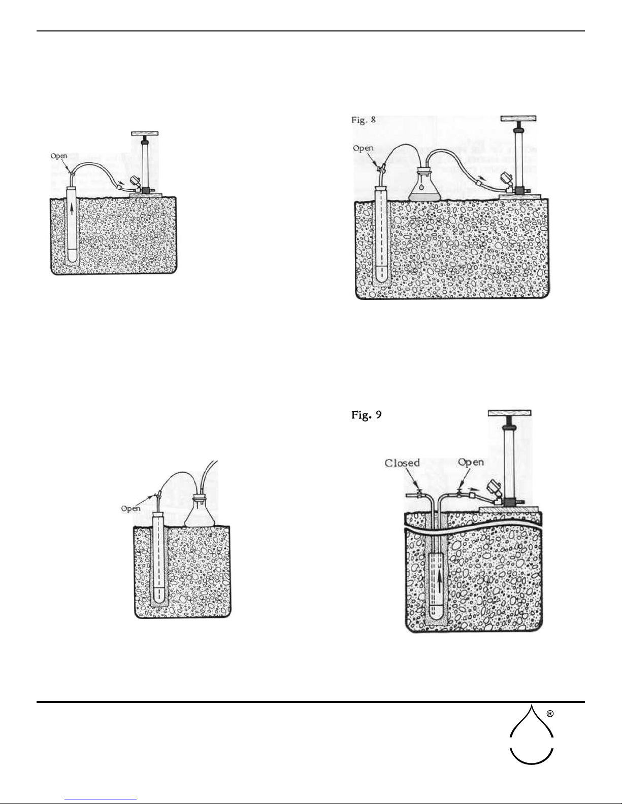
On the Model No. 1920 Pressure-Vacuum Soil Water
Sampler, the pinch clamp on the discharge access tube
is closed and the vacuum tting of the Pressure-Vacu-
um Hand Pump is connected to the pressure-vacuum
access tube, Fig. 9. The pump is then stroked until a
vacuum of about 60 centibars (18” of mercury) is cre-
ated within the sampler, as read on the vacuum dial
gauge connected to the pump. The pinch clamp on the
pressure vacuum access tube is then closed securely
to seal the sampler under vacuum. The hand pump
can now be disconnected for other uses. To remove the
collected soil water sample from the Model No. 1920
Pressure Vacuum Soil Water Sampler, attach the
pressure-vacuum access tube to the pressure tting
of the Pressure-Vacuum Hand Pump, Fig. 10. Place
the discharge access tube in a small collection bottle
and open both pinch clamps. Apply a few strokes on
the hand pump to develop enough pressure within
the sampler to force the collected sample out of the
sampler and into the collection bottle.
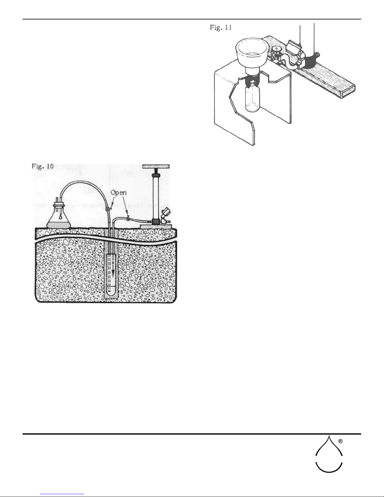
USING THE 2006G2 PRESSUREVACUUM
HAND PUMP AS A VACUUM SOURCE FOR
PORTABLE EXTRACTORS
Connect a length of 3/16” I.D. rubber hose to the
connection tting of the portable extractor and the
vacuum tting of the pump, Fig. 11. A pinch clamp
is placed on the rubber tube and left open. A vacuum
of 80 to 90 centibars is then pulled, using the pump,
within the extractor as read on the vacuum dial
gauge. After the vacuum is pulled, the pinch clamp is
closed, and the pump can be removed for other uses.
The vacuum created within the extractor will cause
the soil water sample to move from the funnel into
the collection bottle.
USING THE PRESSURE/VACUUM HAND
PUMP TO CHECK THE CALIBRATION OF
TENSIOMETER DIAL GAUGES
The adapter tting on the end of the rubber hose is
inserted into the ller end of the tensiometer body
and held tightly against the “0” ring seal to make
a vacuum-tight seal, as explained previously. As a
vacuum is pulled within the tensiometer, the reading
of the vacuum dial gauge on the tensiometer can be
compared with the reading of the vacuum dial gauge
on the pump, which is used as the reference gauge.
In checking the calibration of the vacuum dial gauge,
it is always desirable to lightly tap the gauge case to
relieve the internal friction of the gauge mechanism
to obtain the most accurate reading.
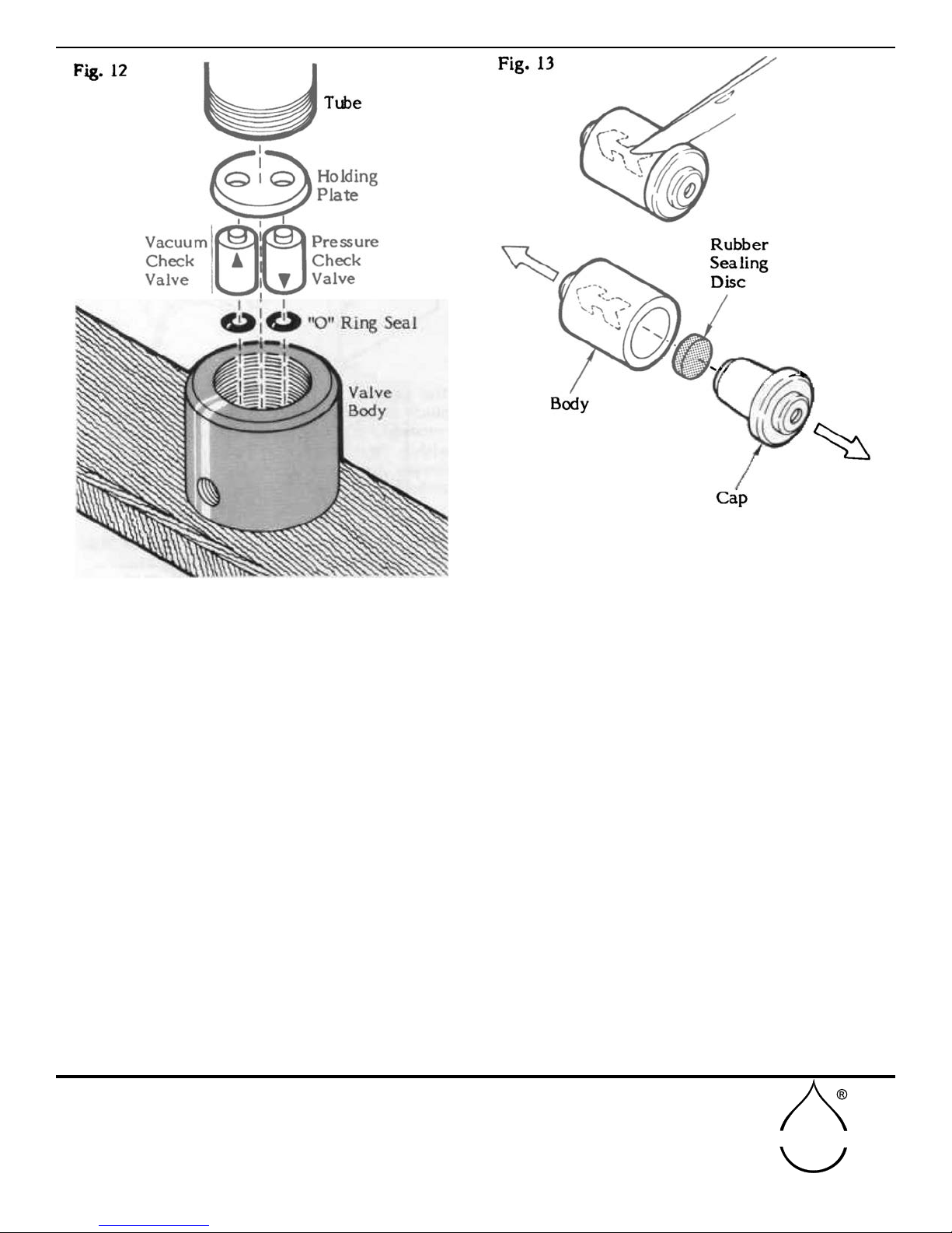
GENERAL CARE AND MAINTENANCE
When the 2006G2 Pressure-Vacuum Hand Pumps are
used for air removal or pulling a vacuum, very little
maintenance of the unit is required. If, however, the
pump will not hold a vacuum or has a pressure leak,
the check valves of the pump could be leaking due
to accumulation of debris. The check valves can be
removed to be ushed and cleaned of particles which
may interfere with their proper sealing action. To
remove the check valves, unscrew the tube from the