Bartels Mikrotechnik mp6 User manual

1
Rev. 3.1 (08.2020)
Operating Manual for
Micropump mp6-series

2
Rev. 3.1 (08.2020)
Content
General............................................................................................................................................................................................................3
Declaration of conformity.....................................................................................................................................................................3
Description of functions........................................................................................................................................................................3
Proper use.......................................................................................................................................................................................................4
Intended purpose.....................................................................................................................................................................................4
Misuse.........................................................................................................................................................................................................4
Staff selection and qualification ........................................................................................................................................................4
About this operating manual...............................................................................................................................................................4
Technical specifications .............................................................................................................................................................................5
Technical Data of the mp6-hyb1...........................................................................................................................................................5
Technical Data of the mp6-liq1, 2..........................................................................................................................................................6
Technical specifications mp6-pi1........................................................................................................................................................7
Technical specifications mp6-pp1.......................................................................................................................................................9
Technical specifications mp6-gas1.................................................................................................................................................. 10
Final inspection..................................................................................................................................................................................... 12
Operating the micropump ...................................................................................................................................................................... 12
Connecting the mp6-series to the cable....................................................................................................................................... 13
Cleaning the system ............................................................................................................................................................................ 14
Typical operation parameters ................................................................................................................................................................ 15
mp6-hyb and mp6-pi.......................................................................................................................................................................... 15
mp6-gas.................................................................................................................................................................................................. 15
mp6-pp.................................................................................................................................................................................................... 15
Combination of micropumps............................................................................................................................................................. 16

3
Rev. 3.1 (08.2020)
General
This operating manual contains all necessary instructions for the installation, commissioning, operation and
maintenance of the mp6-series. The manual is intended to help you achieving optimal results in a short time and
shall also assist avoiding possible sources of errors. The operating manual of the controllers and the accessories are
available separately.
The products have been designed with state-of-the-art technology and in accordance with all relevant safety
regulations. However, a risk of damage to the units, other property, the operator and/or other persons cannot be fully
excluded.
Always ensure that specialized and trained personnel will comply with the following general instructions. Therefore,
please keep this manual and hand out copies as required.
Bartels Mikrotechnik GmbH rejects any responsibility for damages to persons or property resulting from non-
compliance with the instructions in this manual. In this case all warranties shall be void.
Declaration of conformity
Bartels Mikrotechnik GmbH declares that the products are compliant to the RoHS directive 2011/65/EU. The
controllers comply with the requirements of EMV 2014/30/EU and CE markings have been affixed to the devices.
Additionally, the controllers are also compliant to the EU Low Voltage Directive 2014/35/EU.
Description of functions
The micropumps have been developed for the transport of gases or liquids. The controllers have been developed for
operating the micropumps. Bartels Mikrotechnik can assume no liability for damages resulting from the pump media.
This applies especially for hazardous fluids.
The pumps must be operated with Bartels Mikrotechnik electronics. Bartels Mikrotechnik GmbH cannot guarantee
the proper work of the units with customer specific electronics. If other controllers than the ones from Bartels
Mikrotechnik are used, Bartels Mikrotechnik disclaims any warranty.
Moreover, please note that components of the controller and pump are operating with high-voltage. Therefore,
persons wearing pacemakers are recommended to avoid the operating system.
Bartels Mikrotechnik assumes no liability for abnormal handling, improper or negligent use of the micropump and
the controller that is not conform to the specified purpose of the system. This applies especially for micropump
controllers, components and systems of other manufacturers, which have not been certified by Bartels Mikrotechnik.
We guarantee that the micropumps comply with the actual state of scientific and technical knowledge and due to
this, the operational risks are limited to a minimum.
Do not open the housing of the micropump and the controllers. In those cases, Bartels Mikrotechnik cannot issue
a guaranty anymore. Please keep this manual safe and give a copy to all users.

4
Rev. 3.1 (08.2020)
Proper use
Intended purpose
The micropump is intended for pumping liquids or gases with varying flow rates controlled by the electronics. The
controllers are intended for operating the micropumps. Any other use of the micropump or controller unit is deemed
improper.
Do not make any modifications or extensions to the pump or controller without the prior written consent of the
manufacturer. Such modifications may impair the safety of the unit and are prohibited! Bartels Mikrotechnik GmbH
rejects any responsibility for damage to the unit caused by unauthorized modifications to the pump and risk and
liability are automatically transferred to the operator.
Misuse
The use of liquids, which may alone or in combination create explosive or otherwise health-endangering conditions
(including vapors) is not permitted.
Staff selection and qualification
All work in connection with the installation, assembly, commissioning/decommissioning, disassembly, operation,
servicing, cleaning and repairing of the pump and the controller must be carried out by qualified, suitably trained
and instructed personnel. Work on electrical components and assemblies must be carried out by personnel with the
necessary qualifications and skills.
About this operating manual
Warnings and important notes are clearly identified as such in the text. The relevant text sections feature a specific
sign. However, this icon cannot replace the safety instructions. Therefore, carefully read all safety instructions in this
manual. Warnings and important notes in this text are highlighted as shown below, according to the severity of the
damage that might result from non-compliance.
GEFAHR
Danger indicates a hazard with a high level of risk that, if not avoided, will result
in death or serious injury.
5
Rev. 3.1 (08.2020)
Technical specifications
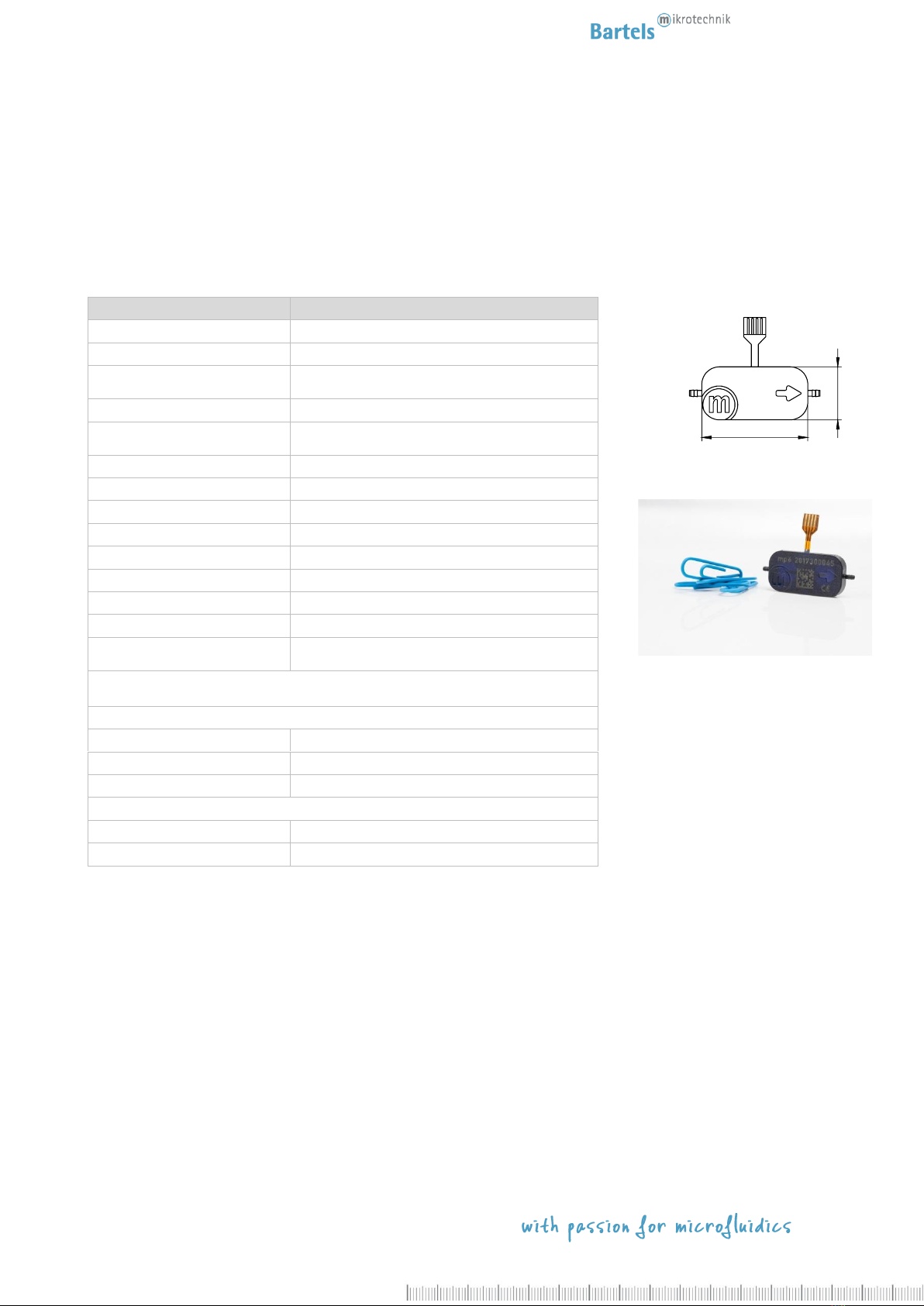
Technical Data of the mp6-hyb1
mp6-hyb
Order code: mp6-hyb
Pump type
piezoelectric diaphragm pump
Number of actuators
2
Dimensions without connectors
30 x 15 x 3,8 mm
1.1811 x 0.5906 x 0.1498 in.
Weight
2 g
Fluidic connectors
barbed tube clip,
(outer diameter 1.9 mm, length 3.5 mm) 2
Electric connector
flex connector 1.25 mm pitch
Power consumption
~ 50 mW 6
Self-priming
yes 3
Pumping media
Liquids and gases
Operating temperature
0–70°C
Life time
5000 h 6
IP code
IP33 7
Material in contact with media
polyphenylsulfone (PPSU) 8
Suitable pump driver
mp-x, mp6-EVA, mp6-OEM, mp6-QuadOEM and mp6-
QuadKEY
Typical values of flow and back pressure for selected media
(values measured with mp-x: 100 Hz, 250 V, SRS):
Liquids –water
Controllable flow range9𝑄
8 µl/min –10000 µl/min
typ. flow rate 𝑄(p=0)
8 ml/min 4
typ. back pressure p (𝑄=0)
500 mbar (7,25 psi) 4
Gases - air
typ. volume flow 𝑄(p=0)
20 ml/min 5
typ. back pressure p (𝑄=0)
80 mbar (1,16 psi) 5
1Typical values. Values can vary under application conditions. Content is subject to changes without notice.
2Recommended tubing: Tygon tubing 1.3 mm inner diameter.
3Conditions: Suction pressure > 10 mbar, DI water, settings mp-x: 100 Hz, 250 V, SRS, the volume flow will be reached after a few
minutes of operation time.
4Conditions: DI water (25°C), room temperature 23°C, settings mp-x: 100 Hz, 250 V, SRS
5Conditions: air, room temperature 23°C, mp-x: 300 Hz, 250 V, SRS
6Conditions: settings mp-x: 100 Hz, 250 V, SRS
7Can be changed to IP44.
8For media compatibility details please find more information in the corresponding media compatibility sheets.
9Controllable with frequency, voltage, signal form and more. Please contact us for more information.
Please find more information concerning the controller and the equipment in the corresponding manuals.
30
15

6
Rev. 3.1 (08.2020)
Technical Data of the mp6-liq1, 2
1Typical values. Values can vary under application conditions. Content is subject to changes without notice.
2Preliminary values, changes will occur on series production
3Recommended tubing: Tygon tubing 1.3 mm inner diameter.
4Conditions: Suction pressure > 10 mbar, DI water, settings mp-x: 100-200 Hz, 250 V, SRS, the max. volume flow will be reached after a
few minutes of operation time.
5Conditions: DI water (25°C), room temperature 23°C, settings mp-x: 200 Hz, 250 V, SRS
6Conditions: settings mp-x: 200 Hz, 250 V, SRS
7Can be changed to IP44.
8For media compatibility details please find more information in the corresponding media compatibility sheets.
9Controllable with frequency, voltage, signal form and more. Please contact us for more information.
Please find more information concerning the controller and the equipment in the corresponding manuals.
mp6-liq
Order code: mp6-liq
Pump type
piezoelectric diaphragm pump
Number of actuators
2
Dimensions without connectors
30 x 15 x 3,8 mm
1.1811 x 0.5906 x 0.1498 in.
Weight
2 g
Fluidic connectors
barbed tube clip,
(outer diameter 1.9 mm, length 3.5 mm) 3
Electric connector
flex connector 1.25 mm pitch
Power consumption
~ 50 mW 6
Self-priming
yes 4
Pumping media
Liquids and mixtures
Operating temperature
0–70°C
Life time
5000 h 6
IP code
IP33 7
Material in contact with media
polyphenylsulfone (PPSU) 8
Suitable pump driver
mp-x, mp6-XEVA, mp6-XOEM, mp6-QuadOEM
and mp6-QuadKEY
Typical values of flow and back pressure for selected media
(values measured with mp-x: 200 Hz, 250 V, SRS):
Liquids –water
Controllable flow range9𝑄
8 µl/min –14000 µl/min
typ. volume flow 𝑄(p=0)
11 ml/min 5
typ. back pressure p (𝑄=0)
800 mbar (11,6 psi) 5
30
15

7
Rev. 3.1 (08.2020)
Technical specifications mp6-pi1
mp6-pi
Order code: mp6-pi
Pump type
piezoelectric diaphragm pump
Number of actuators
2
Dimensions without connectors
30 x 15 x 3,8 mm
1.1811 x 0.5906 x 0.1498 in.
Weight
2 g
Fluidic connectors
barbed tube clip,
(outer diameter 1.9 mm, length 3.5 mm) 2
Electric connector
flex connector 1.25 mm pitch
Power consumption
~ 50 mW 5
Self-priming
yes 3
Pumping media
Liquids and mixtures
Operating temperature
0–70°C
Life time
5000 h 5
IP code
IP33 6
Material in contact with media
Polyimid foil (PI), polyphenylsulfone (PPSU)7
30
15

8
Rev. 3.1 (08.2020)
Suitable pump driver
mp-x, mp6-EVA, mp6-OEM, mp6-QuadOEM and mp6-
QuadKEY
Typical values of flow and back pressure for selected media
(values measured with mp-x: 100 Hz, 250 V, SRS):
Liquids –water
Controllable flow range8𝑄
8 µl/min –8000 µl/min
typ. flow rate 𝑄(p=0)
6 ml/min 4
typ. back pressure p (𝑄=0)
500 mbar (7,25 psi) 4
1 Typical values. Values can vary under application conditions. Content is subject to changes without notice.
2Recommended tubing: Tygon tubing 1.3 mm inner diameter.
3Conditions: Suction pressure > 10 mbar, DI water, settings mp-x: 100 Hz, 250 V, SRS, the max. volume flow will be reached after a few
minutes of operation time.
4Conditions: DI water (25°C), room temperature 23°C, settings mp-x: 100 Hz, 250 V, SRS
5Conditions: settings mp-x: 100 Hz, 250 V, SRS
6Can be changed to IP44.
7For media compatibility details please find more information in the corresponding media compatibility sheets.
8Controllable with frequency, voltage, signal form and more. Please contact us for more information.
Please find more information concerning the controller and the equipment in the corresponding manuals.

9
Rev. 3.1 (08.2020)
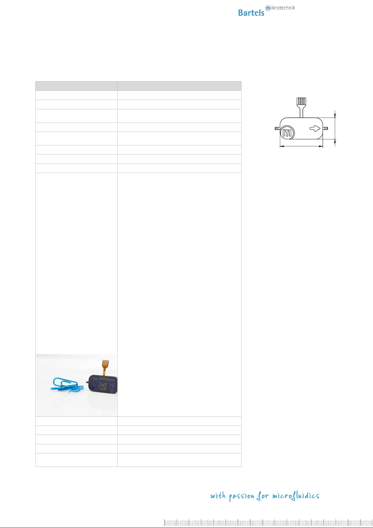
Technical specifications mp6-pp1
mp6-pp
Order code: mp6-pp
Pump type
piezoelectric diaphragm pump
Number of actuators
2
Dimensions without connectors
30 x 15 x 3,8 mm
1.1811 x 0.5906 x 0.1498 in.
Weight
2 g
Fluidic connectors
barbed tube clip, (outer diameter MIN 1.77 mm
- MAX 1.85 mm, length 3.5 mm) 2
Electric connector
flex connector 1.25 mm pitch
Power consumption
~ 50 mW 4
Self-priming
yes 3
Pumping media
Liquids and mixtures
Operating temperature
0 –70°C
Life time
5000 h 4
IP code
IP33 5
Material in contact with media
polypropylene (PP), Polyimid foil (PI) 7
Suitable pump driver
mp-x, mp6-EVA, mp6-OEM, mp6-QuadOEM and
mp6-QuadKEY
Typical values of flow and back pressure for selected media
(values measured with mp-x: 100 Hz, 250 V, SRS):
Liquids –water
Controllable flow range8𝑄
8 µl/min –4000 µl/min
typ. flow rate 𝑄(p=0)
4 ml/min 4
typ. back pressure p (𝑄=0)
500 mbar (7,25 psi) 4
1Typical values. Values can vary under application conditions. Content is subject to changes without notice.
2Recommended tubing: Tygon tubing 1.02 mm inner diameter. MIN & MAX values due to injection molding shrink.
3Conditions: Suction pressure > 10 mbar, DI water, settings mp-x: 100 Hz, 250 V, SRS, the max. volume flow will be reached after a few
minutes of operation time.
4Conditions: Settings mp-x: 100 Hz, 250 V, SRS signal
5Can be changed to IP44.
6Conditions: DI water (25°C), room temperature 23°C, settings mp-x: 100 Hz, 250 V, SRS
7For media compatibility details please find more information in the corresponding media compatibility sheets.
8Controllable with frequency, voltage, signal form and more. Please contact us for more information.
Please find more information concerning the controller and the equipment in the corresponding manuals.
30
15
10
Rev. 3.1 (08.2020)
Technical specifications mp6-gas1
mp6-gas
Order code: mp6-gas
Pump type
piezoelectric diaphragm pump
Number of actuators
2
Dimensions without connectors
30 x 15 x 3,8 mm
1.1811 x 0.5906 x 0.1498 in.
Weight
2 g
Fluidic connectors
barbed tube clip,
(outer diameter 1.9 mm, length 3.5 mm) 2
Electric connector
flex connector 1.25 mm pitch
Power consumption
~ 150 mW 5
Self-priming
yes 3
Pumping media
gases
Operating temperature
0–70°C
Life time
5000 h 5
IP code
IP33 6
Material in contact with media
polyphenylene sulphone (PPSU) 7
Suitable pump driver
mp-x, mp6-EVA, mp6-OEM, mp6-QuadOEM and
mp6-QuadKEY
30
15

11
Rev. 3.1 (08.2020)
Typical values of flow and back pressure for selected media
(values measured with mp-x: 300 Hz, 250 V, SRS):
Gases
typ. volume flow 𝑣 (p=0)
20 ml/min (300 Hz) 5
typ. back pressure p (𝑣=0)
100 mbar (300 Hz) 5, 8
1Typical values. Values can vary under application conditions. Content is subject to changes without notice.
2Recommended tubing: Tygon tubing 1.3 mm inner diameter.
3Conditions: air, room temperature 23°C, settings mp-x: 300 Hz, 250 V, SRS, the max. volume flow will be reached after a few minutes of
operation time.
4Conditions: gases, room temperature 23°C, mp-x: 300 Hz, 250 V, SRS
5Conditions: settings mp-x: 300 Hz, 250 V, SRS
6Can be changed to IP44.
7For media compatibility details please find more information in the corresponding media compatibility sheets.
8The mp6-gas is available as mp6-gas+ version with 150 mbar of back pressure.
Please find more information concerning the controller and the equipment in the corresponding manuals.

12
Rev. 3.1 (08.2020)
Final inspection
After production, the micropumps have to pass a final inspection. They are tested concerning the maximum flow
and back pressure.
Measurement conditions:
Pumping media: distilled water
Temperature: room temperature 23°C
Controller: extended box mp-x
Electrical Input: amplitude of 250 Vpp and SRS-Signal with 100 Hz (for liquids) and 300 Hz (for gases)
Measurements with sensors:
volume flow
range: 0 - 10 ml/min
accuracy: +/- 1% FS (=0.1 ml/min)
pressure
range: 0 –1 bar
accuracy: +/- 0.35% (= 3.5 mbar)
Other application specific outgoing inspections can be offered for all pumps upon customer demand.
In order to guarantee proper function of the delivered goods and exclude transportation damages please check the
incoming devices according to specifications after receipt.
Based on these results a replacement can be carried out within 14 days after delivery free of costs.
Operating the micropump
In this chapter the operation of the micropump during the evaluation is described. This chapter provides information
on the proper connection of the pump with tubing and electrical cables and typical driving parameters to start the
evaluation.
Please connect suitable tubes to the inlet and outlet. The tubing should have an inner diameter of ~1.3 mm for the
mp6, mp6-AIR, mp6-AIR-HP and mp6-pi and ~1.2 mm for the mp6-pp. The micropump has to be connected to a
suitable controller as described in the next sections.
The electrical connection of the micropumps flexible connector is described in the corresponding chapter. The flexible
connector will be attached to the desired controller.
On both type pumps, traces of surface corrosion may appear on the electrical connector. This corrosion only causes
a visual influence, negative effects on the pump performance could not be detected based on performance tests
Tygon; ID = 1,30 mm; AD = 3 mm
Tygon; ID = 1,02 mm; AD = 2,72 mm
Tygon; D = 1,30 mm; AD = 3 mm
Tygon; D = 1,02 mm; AD = 2,72 mm
inlet
flexible connector
outlet
Pumping direction
13
Rev. 3.1 (08.2020)
carried out by Bartels Mikrotechnik. Because of the mechanical fixation inside the electrical connector and due to
the use of elevated driving voltages it is ensured that the pump performance is not affected by the surface corrosion.
In a long term, we will work on improving the production process. Until then, referring to the unrestricted pump
performance we ask our customers to excuse visible defects on the electrical connector.
In general, the micropump can be driven with positive alternating voltages with maximum amplitude of 250 V
at a frequency between 0 and 300 Hz. A rectangular signal results in best fluidic performance while a sine wave
minimizes the audible noise. The actuators must be driven with a 180° phase shift in the signal.
If a pump will be damaged while using a customer’s controller, we do not provide any warranty. We recommend
using our dedicated controllers.
DANGER
THE MP6-SERIES MICROPUMPS ARE OPERATED AT HIGH VOLTAGES. BEFORE
OPERATION, MAKE SURE THAT ALL SPECIFIC REGULATIONS FOR ELECTICAL SAFETY
ARE FULLFILLED.
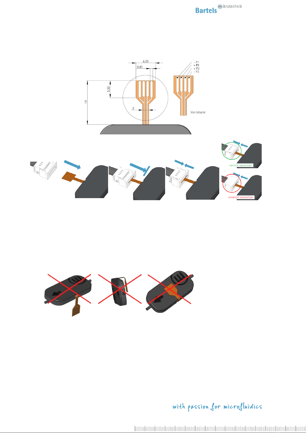
Connecting the mp6-series to the cable
The pumps can be connected via a FCC connector. The layout of the connector and pin assignment of the pumps is
as shown below. Each piezo (P1 / P2) has a single lead for the negative (-P1/-P2) and the positive (+P1/+P2) supply
voltage.
The recommended connector is a 4-pin 1.25 mm pitch FCC connector manufactured by Molex. The straight
version part number 39 53 2045. An alternative is the angulated version with the part number 39 53 2044.
The connector is available in different versions to fit various applications. Reference drawings and further
specifications are available under www.molex.com .
The recommended maximum wire length between controller and the pump is 1 m. The customer has to assure that
the assembly of pump, controller and electrical connection complies with the EMC regulations and electrical safety
in the specific field of application.
To connect the pumps and Molex, refer to following three figures. Orientate both components as indicated on the
first picture, the pumps facing downwards with its serial number marking (!) and the Molex connector with the four
small openings visible from above. Then insert the mp6/mp6-pp flex into the Molex connector (Step1). Close the
Molex connector to complete the interconnection between both components (Step 2).
14
Rev. 3.1 (08.2020)
1 Änderungen vorbehalten
If the pump should be removed again, the Molex connector needs to be opened before removal!
In order to prevent damage to the flexible cable, the following points should be considered for the final pump
assembly:
-the flexible connector must not be bent around sharp edges or kinked
-the flexible connector must not be bend on top or bottom of the pump
-the Molex connector is not water tight, additional sealing with e.g. silicone will be necessary
-fixation of the Molex connector in the final assembly is recommended
The Molex flex cable has contacts only on one side, so it can be connected to the Molex connector only in one way.
If connected in the other way, the pump will not function.
Cleaning the system
The pump can be washed with water, alcohol (isopropanol) or if necessary with weak acid by pumping or by flushing
with the help of a syringe. Flushing is only possible in pump direction!

15
Rev. 3.1 (08.2020)
Typical operation parameters
mp6-hyb and mp6-pi
The description here applies to the medium water. For the delivery of gases, please read the section to mp6-gas.
Please note that the regular mp6-hyb, as well as the mp6-liq can also pump gases, but has not been specially
measured for this purpose.
To achieve individual flow rates and optimal flow conditions, the driving parameters need to be tested, optimized and
confirmed by testing under full application conditions. The typical flow rates given by us have been determined using
an mp-x controller with SRS wave form. Please refer to the corresponding manual for operation of the mp-x
controller.
If lower flow rates are required, it is advisable to use a restrictor for throttling and to operate the pump at the
recommended parameters.
As a general experimental approach, we recommend a high amplitude at varying frequencies. The performance
depends on the environmental conditions.
mp6-gas
Driving the micropump with the controller mp-x at 300 Hz with 250 V, flow rates of typ. min. 20 ml/min and
backpressures of typ. min. 100 mbar can be achieved.
In general, for driving the pump with air the following points should be taken into account:
-Higher frequencies should be used (compared to pumping water).
-Large amplitudes respectively driving voltages should be used.
With low frequencies and amplitudes, the volume flow and pressure generation is rather weak due to the passive
character of the valves inside the micropump. These valves are more effective with fast and high pressure changes
induced by the actuator.
If the desired flow rates should be small, the application of a restrictor is recommended. Please contact us about the
right choice of the restrictor!
Please note the different frequency ranges of the control units.
To minimize audible noise, using the sine signal is recommended.
The signal has influence on volume flow and back pressure, thereby applies rectangular > SRS > sine.
mp6-pp
Again the following applies to the media water. Note that the mp6-pp can pump gases too, but is not specifically
measured for it.
To achieve individual flow rates and optimal flow conditions, the driving parameters need to be tested, optimized and
confirmed by testing under full application conditions. The typical flow rates given by us have been determined using
an mp-x controller with SRS wave form. Please refer to the corresponding manual for operation of the mp-x
controller.

16
Rev. 3.1 (08.2020)
If lower flow rates are required, it is advisable to use a restrictor for throttling and to operate the pump at the
recommended parameters.
As a general experimental approach, we recommend a high amplitude at varying frequencies. The performance
depends on the environmental conditions.
Combination of micropumps
The micropumps can be combined to achieve higher flow rates or pressure than the single unit can generate.
With series connection, the pressures add up.
With parallel connection, the volume flows add up.
All values are approximate and no guarantee of specific technical properties.
Changes in the course of technical progress are possible without notice.

17
Rev. 3.1 (08.2020)
Contact Data:
Bartels Mikrotechnik GmbH
Konrad-Adenauer-Allee 11
44263 Dortmund Germany
www.bartels-mikrotechnik.de
info@bartels-mikrotechnik.de
Tel: +49-231-47730-500
Fax: +49-231-47730-501
Visit our Website
www.bartels-mikrotechnik.de
for further information on applications.
Tutorials and helpful answers to frequently asked
questions can be found in our FAQ
http://blog.bartels-mikrotechnik.de
or on our YouTube channel
https://www.youtube.com/user/BartelsMikrotechnik
Social Media: Facebook, Twitter, Instagram, LinkedIn
Other manuals for mp6
1
This manual suits for next models
6
Table of contents
Other Bartels Mikrotechnik Water Pump manuals


