Sol-Expert group 76336 User manual
Firmenanschrift aufbewahren -
Keep the address of the company -
Veuillez conserver l'adresse -
Adres bewaren -
Nicht geeignet für Kinder unter 3 Jahren! - Verschluckbare
Kleinteile! Not suitable for children under 3 years! -
Contains small parts! Ne convient pas pour les enfants de moins
de trois ans! - Contient de petites pièces pouvant être absorbées! Niet
geschikt voor kinderen beneden 3 jaar! - Kleine onderdelen Kunnen worden ingeslikt!
Tel.: +49 (0)7502 - 94115-0 - Fax: +49 (0)7502 - 94115-99
[email protected] - www.sol-expert-group.de
SOL-EXPERT group, C.Repky - Mehlisstrasse 19 - D-88255 Baindt
SOL-EXPERT
group
group
No. 76336
MADE IN EUROPE
10+
Return the device
to a certified provider at
the end of its useful life!
Generally: Please return the circuit board to a certified provider at the end of its useful life. These will then ensure it is disposed of in
compliance with directives. This is good for the environment and an important part of actively protecting the environment.
ENVIRONMENTAL NOTES
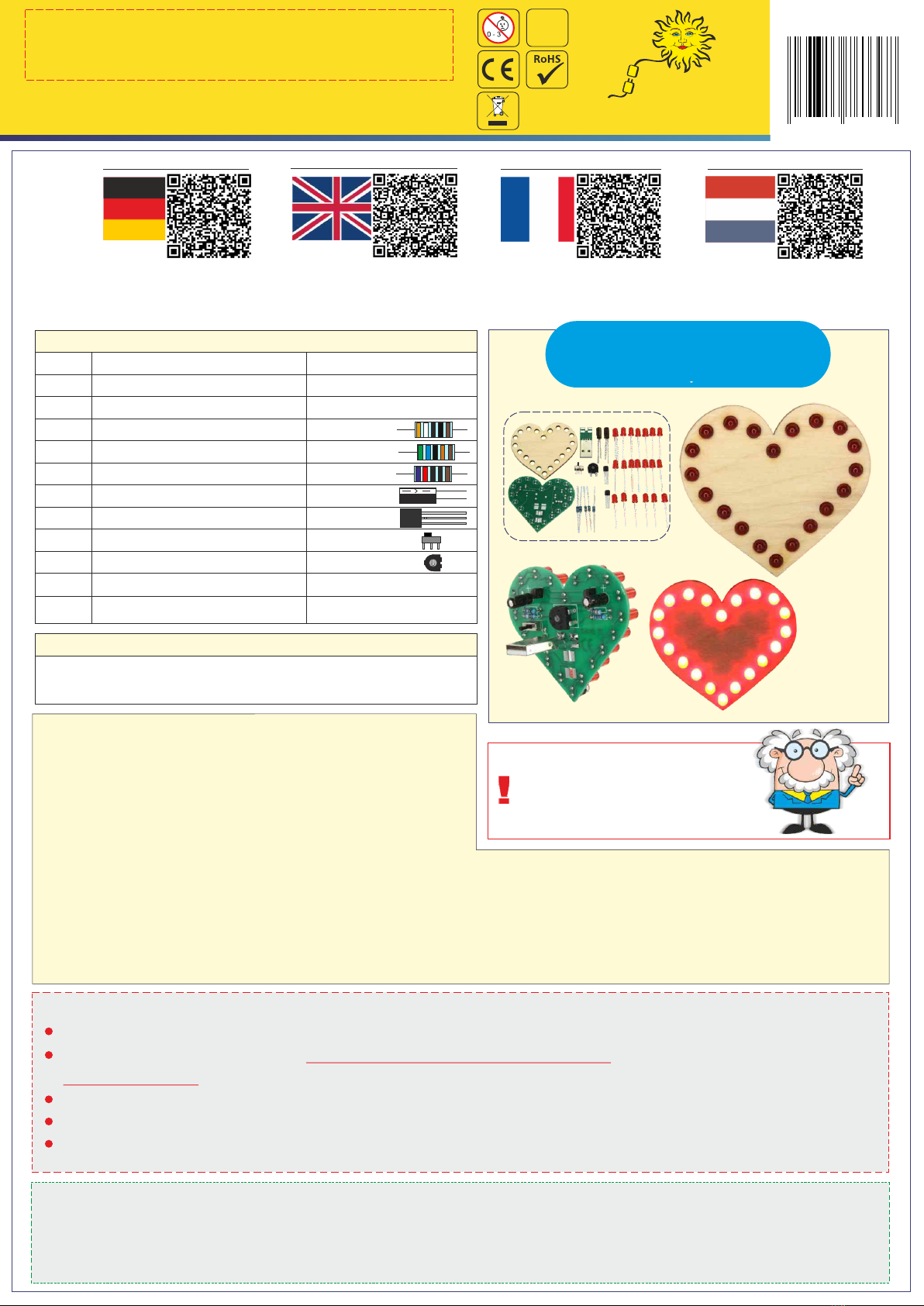
The 'Blinking Heart' soldering kit
The 'Blinking Heart' soldering kit is excellent to practice soldering on a
circuit board. Over 30 parts are soldered onto the circuit board step by
step according to the instructions. Once the kit is assembled the heart
can be operated in steady or blinking mode.
In blinking mode you can then also adjust the blink speed via the
potentiometer. So you can send messages, e.g. slow blinking: I love you - rapid blinking: I really love you!
Decorate the included plywood front any way you'd like and install if desired. Dimensions: 70 x 70 mm, over 30 parts.
The 'Blinking Heart' electronics building kit is powered via power bank or via USB port. This eliminates costly batteries.
Qty. Part Value/Description
1 Circuit board 76320
20 LED 5 mm Colour red
2 Resistor (R5/R6) 3K9 Ohm
2 Resistor (R1/R4) 56 Ohm
1 Resistor (R7) 620 Ohm
2 Capacitor (C1/(C2) 47 uF/10V
2 Transistor (T1/T2) BC547B
1 Switch (SW1) SS12D01
1 Pot (R2) 100K ohm
1 USB connector installed
1 Front panel 1-pc.
Heart with blinking or steady lights
soldering kit, powered via power bank
or USB port
Parts list Check and sort out parts
BC547B
You will also need:
Soldering iron, solder, wire cutters, tweezers, power bank
or USB port
47 uF
Recommendation for children
and teenagers: Assembly and
soldering should be supervised
by an adult.
4 0 3 7 3 7 3 7 6 3 3 6 8
IMPORTANT SAFETY NOTES
Keep this manual for future reference! It contains important information.
This kit is intended for USB power only.
The soldering iron, solder and the parts being soldered become very hot. Be very careful!
Always use a mat when soldering! This prevents parts and the circuit board from slipping.
We recommend using a soldering iron holder to set the soldering iron down safely during use.
Never connect the kit to 230 V mains voltage!
Acute danger to life!
QR Codes
Cliquez ici pour les instructions:
Klik hier voor de instructies:
https://www.sol-
expert-group.de/All-
about-soldering/Smart-kits-for-
soldering/Solder-kit-heart-with-flashing-
function-and-permanent-
light::1263.html?language=en
https://www.sol-
expert-
group.de/Rond-solderen/Clever-kits-voor-het-
solderen/Soldeerkit-hart-met-knipperende-functie-
en-permanent-licht::1263.html?language=nl
Click here for the instructions:
Hier geht es zur Anleitung:
https://www.sol
-expert-
group.de/Rund-ums-Loeten/Pfiffige-
Loetbausaetze/Loetbausatz-Herz-mit-
Blinkfunktion-und-
Dauerleuchten::1263.html?language=de
https://www.sol-
expert-
group.de/Autour-de-la-soudure/Kits-
astucieux-pour-la-soudure/Coeur-de-kit-de-
soudure-avec-fonction-clignotante-et-
lumiere-permanente::1263.html?language=fr
Conrad No.
1818582
ASSEMBLY INSTRUCTIONS
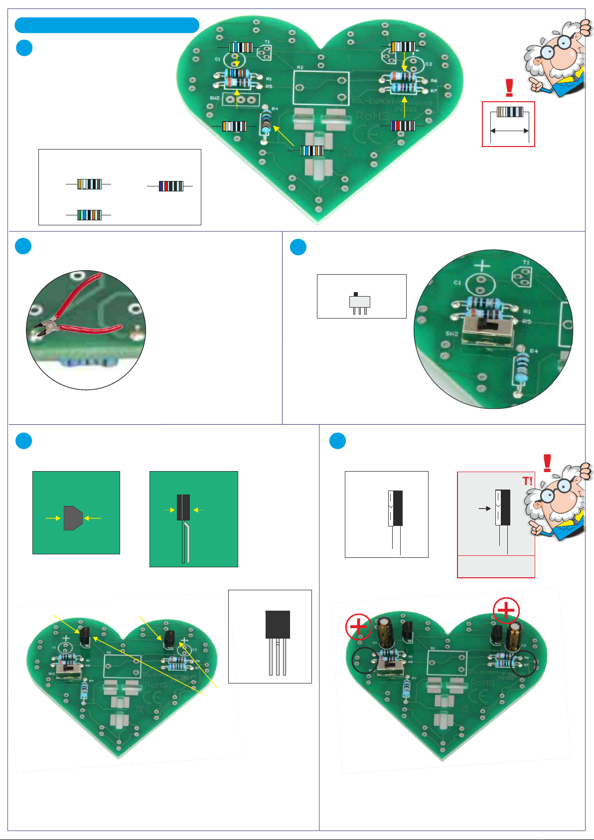
A
3K9 Ohm
2 x
56 Ohm
2 x
620 Ohm
1 x
10 mm
Parts needed Bend the resistor
wires so they slide
easily between
the lands!
Circuit board direction for
soldering: 'RoHS' must be
visible, then the board is on
the correct side.
Solder 5 resistors into place,
paying attention to the
resistances. The resistor
polarity is not important! 620 Ohm
3K9 Ohm
3K9 Ohm
56 Ohm
56 Ohm
Solder 2 transistors in place.
Bend the middle leg of the transistor slightly to the back (2).
Pay attention to the direction (1)! Solder 2 capacitors in place.
Pay attention to the polarity!
flat side
rounded side
Transistor top view
1
flat side
rounded
side
Transistor side view
bend middle
leg to the
back
2Parts needed
47 uF
2 x
47 uF
+
-
IMPORTANT!
Imprint „-“
The longer
leg is „ “+
++
--
C
Parts needed
Trim excess wires.
B
After soldering, use wire
cutters to trim the excess
wires at the back to
approx. 2 mm.
D E
Solder switch in place
Trim excess wires.
2 x BC547B
Parts needed
Flat side
Rounded
side Rounded
side
Flat side
Rounded
side Rounded
side
Turn over the circuit board and solder the other 4 points
on the front.
2 soldering
points
4
soldering
points
2 soldering points
Solder potentiometer in place.
Part needed
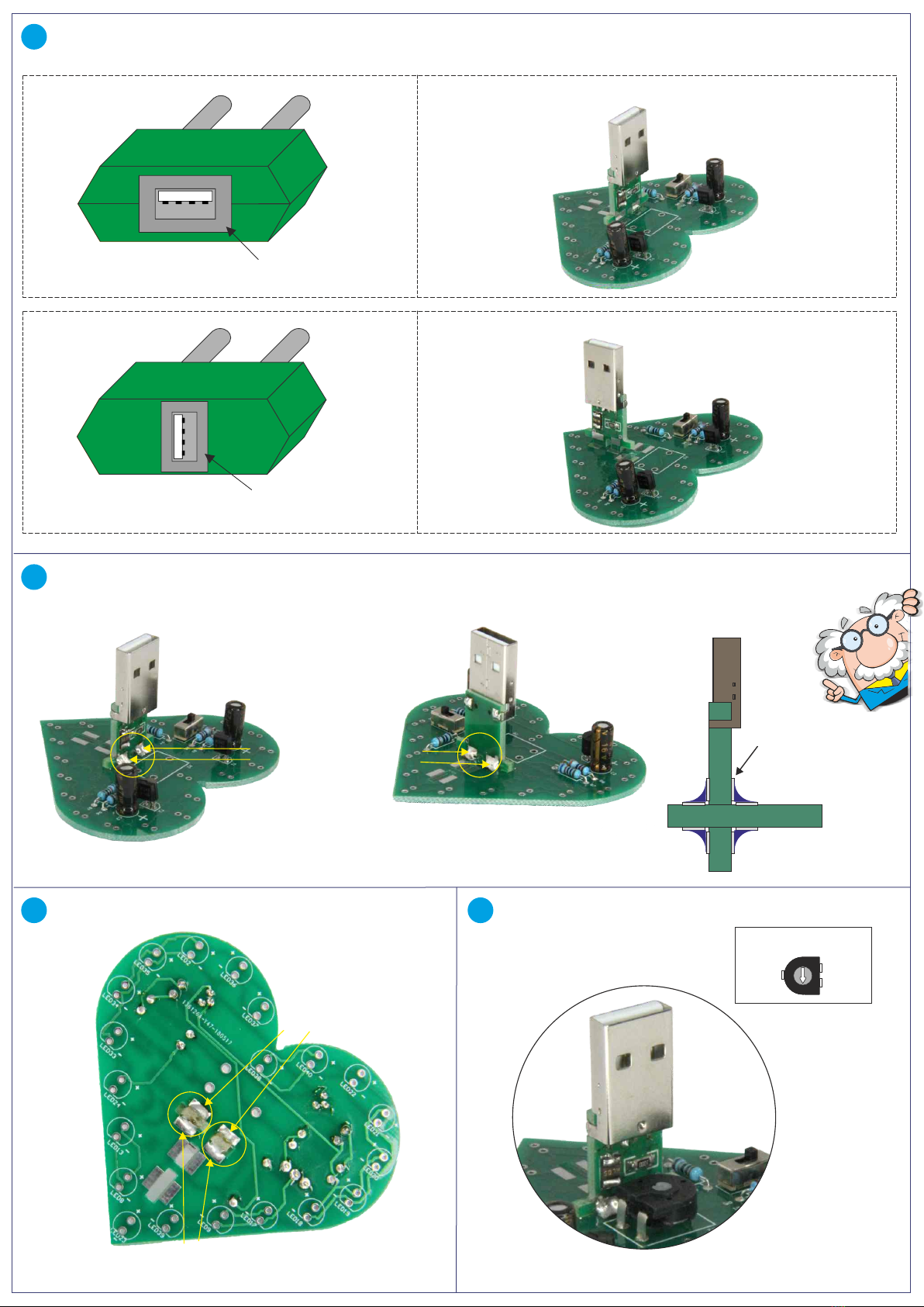
Before installing the USB connector you will need to determine if the USB port on the power bank or the USB adapter you
will be using to power the heart is horizontal or vertical.
After choosing the correct position you can solder the USB connector in place. First slightly solder in one area,
adjust the USB connector (if crooked), then solder on the other 3 areas. Once all 4 points have been soldered, the USB
will then be firmly attached.
F
G
H I
USB connector position for horizontal USB port:
USB connector position for vertical USB port:
horizontal USB port
vertical USB port
Power bank or wall plug
Power bank or wall plug
The solder
connects the
solder pads.
circuit board
Solder
Solder
Solder
Solder
circuit board
Changes and errors reserved - July 2018 / Christian Repky ©
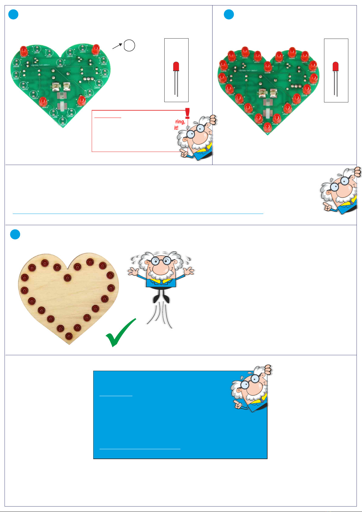
Solder remaining 16 LEDs in place.
Pay attention to the polarity!
Turn the circuit board over and solder 4 LEDs in place from the front.
(LED 2 / LED 21 / LED 13 / LED 9) Pay attention to the polarity - polarity
shown on the circuit board! The longer leg on the LED is always POSITIVE!
flat side
= short wire
-
+Parts
needed
16 x
-
+
TROUBLESHOOTING:
No LEDs on:
- Check all soldering points
- Did you push the power button on the power bank
to switch it on?
- Check the transistors for short-circuits
- Is the power bank charged?
Specific LED does not light up:
- Check the soldering points for the LED
J K
Once plugged in, all LEDs should now
flicker. Depending on the setting they will
either be steady or blink. You can use a
small screwdriver to adjust the speed on
the potentiometer.
Slide the front panel over the LEDs, using a little pressure.
If necessary, adjust the LEDs!
L
ATTENTION: the soldered on LEDs
must be flat on the board. When soldering,
make sure the legs do not short-circuit!
A short-circuit is caused by e.g.
accidentally soldering together
2 wires with solder.
VISUAL INSPECTION:
Lean back in your chair and take a mental break. Once you feel relaxed, read through the assembly instructions again
from the start, checking if you did everything as instructed. Pay particular attention to short-circuits and the resistances,
etc. Take your time and once you have checked all items, plug the USB connector into a power bank or a USB port.
Some power banks have a power button which needs to be pushed for the circuit board to work.
Parts
needed
4 x
-
+
This manual suits for next models
1
Other Sol-Expert group Toy manuals


