Sol Welding FUTURA Series User manual

FUTURA 3500 C
FUTURA 4500 C
FUTURA 3500 S
FUTURA 4500 S-W
FUTURA 5500 S-W
WIRE FEEDER TR 21
FUTURA SERIES
Instruction Manual
Betriebsanleitung
Livret d'Instructions
Manuale Istruzioni
Manual de instrucciones Sol Welding
The present manual must be integrated by ”Operating ad service manual CE”
Diese Bedienungsanleitung muß durch die “CE Betriebs- und Wartungsanleitung” ergänzt werden.
Ce livret doit être completéavec le "Manuel d'usage et entretien CE"
Il presente manuale deve essere integrato dal ”Manuale d’uso e manutenzione CE”
El presente manual debe ser acompañado por el “Manual de uso y mantenimiento CE”Printed in date 21/04/08 Rev. 00

GB
COOLER UNIT
Warning! When working with the cooling unit, it should exclu-
sively be used the coolant supplied by Sol Welding.
Warnung! Nur Sol Welding - Kühlflußigkeit in Wasserkühler
verwenden.
Attention! Pour le groupe réfrigérant, utiliser exclusivement
du liquide réfrigérant fourni par Sol Welding.
Attenzione! Per il gruppo refrigerante, utilizzare esclusiva-
mente liquido refrigerante fornito da Sol Welding.
Atencion! En los grupos de refigeración utilize unicamente el
refrigerante proveido por Sol Welding.
D
F
I
E
Warning!

3
Instruction Manual / Betriebsanleitung / Livret d'Instructions / Manuale Istruzioni / Manual de instrucciones FUTURA SERIES
INDEX
1 POSSIBLE APPLICATION / DIE AUSWAHL DES RICHTIGEN ZUBEHÖRS / pag. 4
UTILISATION AUTORISEE / USO CONSENTITO / APLICACIONES POSIBLES
ROUTINE MAINTENANCE / ORDENTLICHE WARTUNG / pag. 6
ENTRETIEN NORMAL / MANUTENZIONE ORDINARIA /
MANTENIMIENTO ORDINARIO
2 ADJUSTMENT DESCRIPTION / EINSTELLEN DER SCHWEISSPARAMETER / pag. 8
DESCRIPTION COMMANDES / DESCRIZIONE COMANDI /
DESCRIPCIóN DE LOS COMANDOS
3 POWER SUPPLY INPUT / NETZANSCHLUß/ pag. 22
LACAGE A' RESEAU / ALLACCIAMENTO A RETE /
CONEXIÓN A LA RED DE ALIMENTACIÓN
4 MIG INSTALLATION / DAS SCHWEIßEN IN DER FUNKTION MIG/MAG / pag. 24
INSTALLATION MIG/MAG / INSTALLAZIONE MIG / INSTALACIóN MIG
SPEED WIRE ADJUSTMENTS’ / DRAHTVORSCHUBREGELUNG pag. 29
RÉGULATION VITESSE DU FIL / REGOLAZIONE DELLA VELOCITA’FILO
REGULACIÓN VELOCIDAD DEL HILO
2/4 TIMES - TIMER SELECTION / AUSWAHL 2-4-TAKT - TIMER Betrieb pag. 30
SÉLECTION 2/4 TEMPS - TIMER / SELEZIONE 2/4 TEMPI - TIMER
SELECCION 2/4 TIEMPOS - TIMER
TIMER ADJUSTMENTS’/ TIMER-EINSTELLUNG / RÉGULATION TIMER pag. 31
REGOLAZIONE TIMER / REGULACIÓN TIMER
BBT ADJUSTMENTS’(Burn Back Time) / BBT-EINSTELLUNG pag. 32
RÉGULATION BBT / REGOLAZIONE BBT / REGULACIÓN BBT
SOFT START ADJUSTMENTS’/ SOFT-START EINSTELLUNG pag. 33
RÉGULATION SOFT START / REGOLAZIONE SOFT START
REGULACIÓN SOFT START
5 TECNICAL SPECIFICATION / SPECIFICHE TECNICHE pag. 34
SPARE PARTS LIST FUTURA 3500 C / FUTURA 4500 C pag. 35
SPARE PARTS LIST FUTURA 3500 S / FUTURA 4500 S-W / FUTURA 5500 S-W pag. 39
SPARE PARTS LIST WIRE FEEDER TR 21 pag. 43
SPARE PARTS LIST 4 rolls wirefeeder group layout pag. 45
ELECTRIC SCHEMES pag. 47

4
Instruction Manual / Betriebsanleitung / Livret d'Instructions / Manuale Istruzioni / Manual de instrucciones FUTURA SERIES
1. POSSIBLE APPLICATON
The power source type FUTURA 3500 C, FUTURA 4500 C, FUTURA 3500 S,
FUTURA 4500 S-W and FUTURA 5500 S-W are suited for Mig Mag welding in the
range of 350/550 A.
•The cable assembly can have a max lenght of 50 mt.
•The correct working of the water cooling is granted by connection cable
max 7 mt height.
•It is forbidden to use the equipment for different application from the ones listed
in this manual.
Adifferent use from the one here described can compromise the security of
work and the reability of the equipment.
1. DIE AUSWAHL DES RICHTIGEN ZUBEHÖRS
Die Schweißstromquelle FUTURA 3500 C, FUTURA 4500 C, FUTURA 3500 S,
FUTURA 4500 S-W, FUTURA 5500 S-W ist geeignet für die Schweißverfahren
MIG/MAG bis 350/550 Amp.
•Um in jeder Situation eine ausreichende Wasserkühlung zu gewährleisten, sollte
das Zwischenschlauchpaket nicht länger als 7 Meter sein.
•Es sollte kein anderes Zubehör als das in dieser Betriebsanleitung envähnte
eingesetzt wer den.
Sollten Sie Ihr SolWelding-Schweißgerät unter den oben geschilderten
Umständen betrieben wollen, setzen Sie sich bitte mit Ihrer Sol Welding-
Service-Niederlassung in Verbindung.
GB
D
1. UTILISATION AUTORISEE
Les gerateurs type FUTURA 3500 C, FUTURA 4500 C, FUTURA 3500 S, FUTURA
4500 S-W, FUTURA 5500 S-W sont concus pour des applications MIG/MAG avec
gamma 350/550 Amp.
•Le faisceau de cables de connexion peut avoir une longueur allant jusq'a' 50 m.
•La hauteur de refoulement de l'unite' de refroidissement est au maximum de 7 m.
Toute appliction differente de celles indiquees n'est pas autorisee et peut
compromettre la securite' de travail et la fiabilite' de l'installation.
F

5
Instruction Manual / Betriebsanleitung / Livret d'Instructions / Manuale Istruzioni / Manual de instrucciones FUTURA SERIES
1. Aplicaciones posibles:
Los generadores tipo FUTURA 3500 C, FUTURA 4500 C, FUTURA 3500 S,
FUTURA 4500 S-W, FUTURA 5500 S-W han sido creados para soldar mig/mag
en una gamma de 350 / 550 A.
•El paquete de cables de conexión pude ser la máximo de 50 mt..
•La distancia máxima a la unidad de refrigeración es de 7 mt.
Toda aplicación diversa de las enumeradas puede comprometer la seguri-
dad del trabajo y la confiabilidad de la máquina. Concecuentemente, las
mismas no estan permitidas.
E
1. USO CONSENTITO
I generatori tipo FUTURA 3500 C, FUTURA 4500 C, FUTURA 3500 S, FUTURA
4500 S-W e FUTURA 5500 S-W sono sviluppati per applicazioni Mig Mag con
gamma 350/550 A.
•Il fascio cavi di collegamento puòesere lungo fino a 50 mt.
•La prevalenza dell’unitàdi raffreddamento èdi max 7 mt.
Ogni applicazione diversa da quelle elencate non èconsentita e puòcom-
promettere la sicurezza di lavoro e l’affidabilitàdell’impianto.
I
6
Instruction Manual / Betriebsanleitung / Livret d'Instructions / Manuale Istruzioni / Manual de instrucciones FUTURA SERIES
ROUTINE MAINTENANCE
Prevent metal powder from accumulating inside the equipment.
Disconnect the power supply before every operation !
Carry out the following periodic controls on the power source:
•Clean the power source inside by means of low- pressure compressed air and soft bristel brushes.
•Check the electric connections and all the connection cables.
For the use and maintenance of the pressure reducers, consult the specific manuals.
ORDENTLICHE WARTUNG
Vermeiden, daßMetallstaub in der Stomquelle sich ansammelt.
Vor jedem Wartungseingriff die Strozuführung von der Anlage trennen.
Den Generator regelmäßig prüfen:
•Den Generator innen mit Druckluft mit niederem Druck und mit weichen Pinseln reinigen.
•Elektrische Verbindungen und Anschlußkabel prüfen.
Für die Instandhaltung und den Gebrauch der Druckreduzierer die entsprechenden Anleitungen zu Hilfe nehmen.
D
GB
ENTRETIEN NORMAL
Eviter q'on accumule de la poudre méetallique dans l'interieur de l'installation.
Oter l'alimentation à a' l'installation avant chaque
intervention !
Contolles periodiques au generateur:
•Accomplir le nettoyage interieur utilisant l'air comprimpree a' basse pression et pinceau a' soie douce.
•Contoller les jointages electriques et tous les cables de connexion.
Pour l'entretien et l'usage des reducteurs de pression, consulter les livrets d'instructions specifiques.
F
7
Instruction Manual / Betriebsanleitung / Livret d'Instructions / Manuale Istruzioni / Manual de instrucciones FUTURA SERIES
MANTENIMIENTO ORDINARIO
Evitar el acúmulo de limadura metálica al interno de la máquina.
Desconectar la alimentación antes del mantenimiento.
Controles periódicos:
•Limpiar el interior con aire comprimido a baja presión y pinceles de cerdas suaves.
•Controlar las conexiones eléctricas de todos los cables.
Para realizar mantenimineto de reductores de presión consultar el manual del fabricante.
E
MANUTENZIONE ORDINARIA
Evitare che si accumuli polvere metallica all’interno dell’impianto.
Togliere alimentazione all’impianto prima di ogni intervento !
Controlli periodici al generatore:
•Efettuare la pulizia interna utilizzando l’aria compressa a bassa pressione e pennelli a setola morbida.
•Controllare le connessioni elettriche e tutti i cavi di collegamento.
Per la manutenzione e l’uso dei riduttori di pressione consultare i manuali specifici.
I
8
Instruction Manual / Betriebsanleitung / Livret d'Instructions / Manuale Istruzioni / Manual de instrucciones FUTURA SERIES
2. ADJUSTMENT DESCRIPTION / EINSTELLEN DER
SCHWEISSPARAMETER /DESCRIPTION COMMANDES
DESCRIZIONE COMANDI /DESCRIPCIóN DE COMANDOS
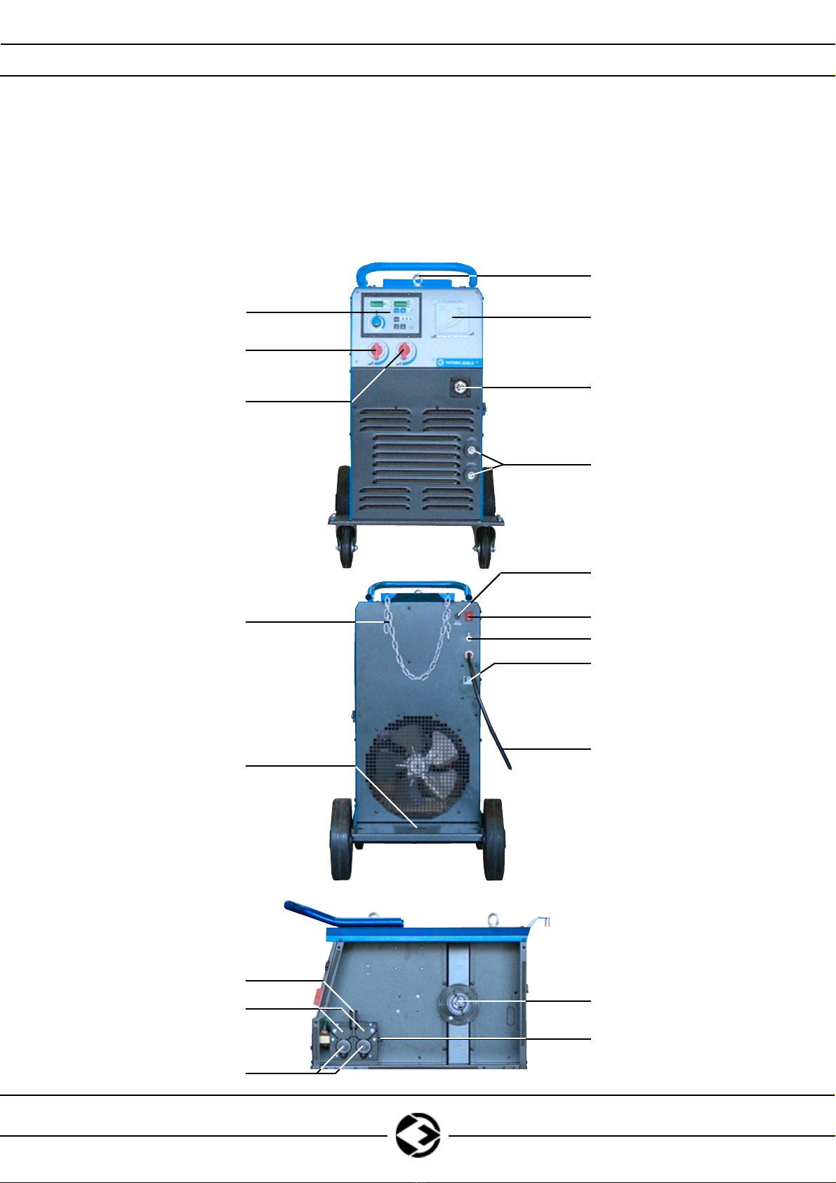
FUTURA C SERIES
(compact series)
7
1
2
3
4
5
6
Fig. 1
8
9
10
11
12
14
13
19
18
17
15
16
See page 16
9
Instruction Manual / Betriebsanleitung / Livret d'Instructions / Manuale Istruzioni / Manual de instrucciones FUTURA SERIES
2. ADJUSTMENT DESCRIPTION / EINSTELLEN DER
SCHWEISSPARAMETER /DESCRIPTION COMMANDES
DESCRIZIONE COMANDI /DESCRIPCIóN DE COMANDOS
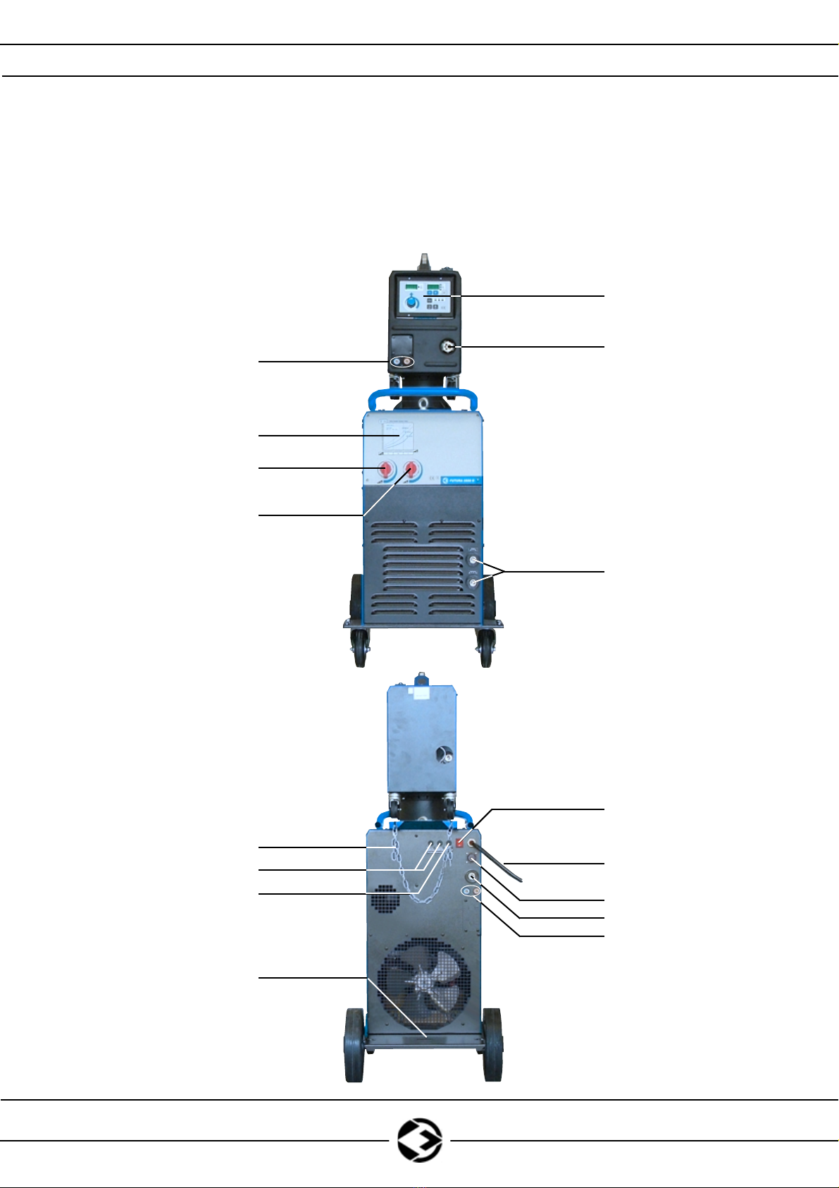
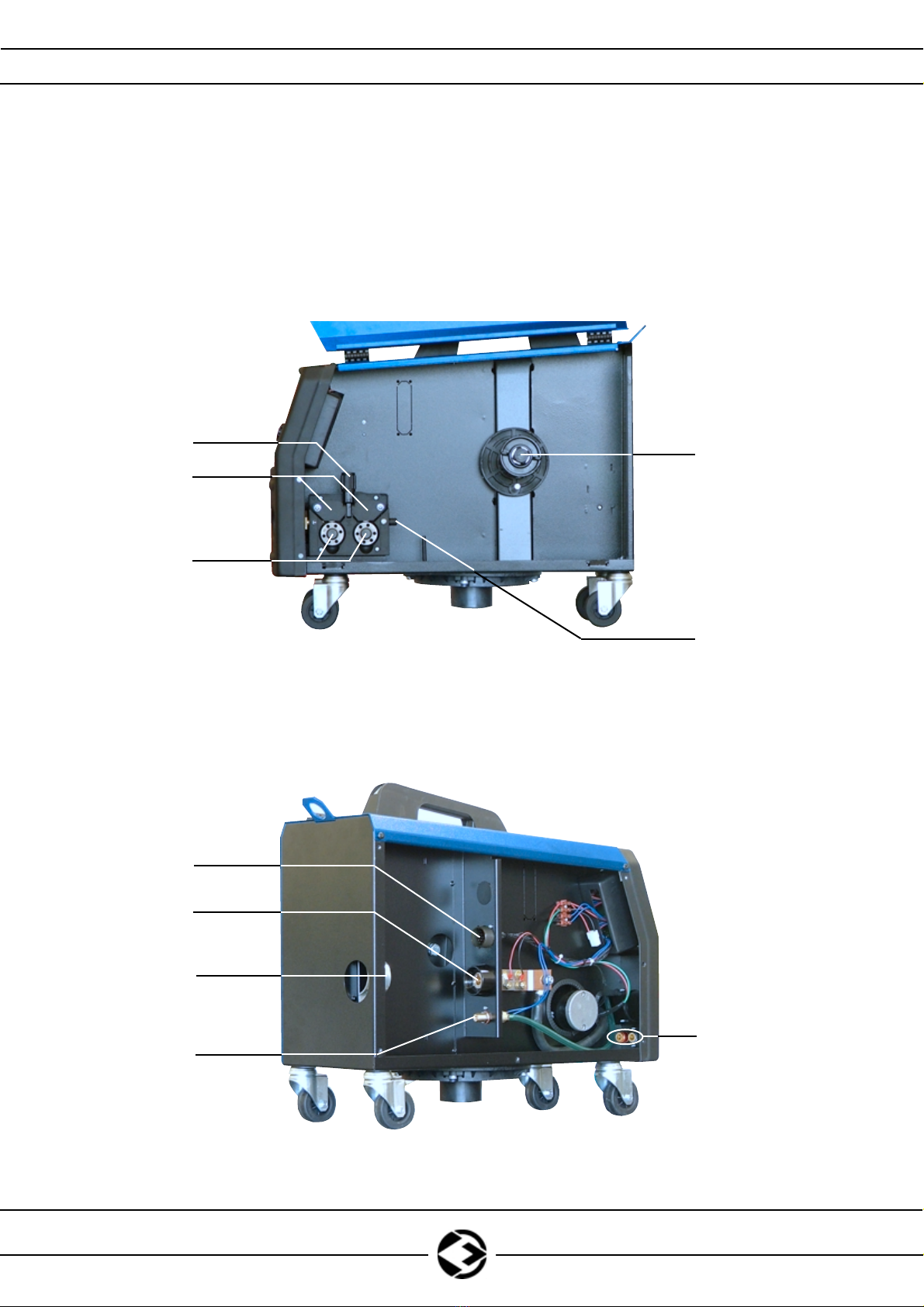
FUTURA S SERIES
(separated series)
7
3
4
5
6
2
20
(optional)
9
12
21
13
23
14
Fig. 2
22
20
(optional)
on
FUTURA 3500 S
8
See page 16
10
Instruction Manual / Betriebsanleitung / Livret d'Instructions / Manuale Istruzioni / Manual de instrucciones FUTURA SERIES
2. ADJUSTMENT DESCRIPTION / EINSTELLEN DER
SCHWEISSPARAMETER /DESCRIPTION COMMANDES
DESCRIZIONE COMANDI /DESCRIPCIóN DE COMANDOS
TRAINO TR 21
(Wire feeder)
26
25
24
10
20
15
16
19
18
17
Fig. 3
(optional)

11
Instruction Manual / Betriebsanleitung / Livret d'Instructions / Manuale Istruzioni / Manual de instrucciones FUTURA SERIES
ADJUSTMENTS AND FEATURES ON FUTURA SERIES
Refer to Fig. 1-2-3.
POS. 1: Bull eye hook to move the generator.
POS. 2: Wire speed and voltage step relation table.
(It help to find easely the wire speed value in relation to voltage step).
POS. 3: MIG/MAG torch connector. (Includes: power output, GAS outlet and torch
switch connection).
POS. 4: Negative output sockets (-). Low or high inductance.
POS. 5-6: Voltage Switches: these switches are positioned on the front panel of the
machine.They allow the selection of the arc voltage. Switch (6) selects the
main voltage regulation and (5) the fine voltage regulation.
POS. 7: Front panel control board (See page 16).
POS. 8: Protection motor fuse.
POS. 9: Power Source Main Switch “ON - OFF”.
POS. 10: In-let GAS connector.
POS. 11: Power supply cooler unit connection plate.
POS. 12: Power input cable.
POS. 13: GAS tank position slot.
POS. 14: Gas tank securing chain.
POS. 15: Wire spool support.
POS. 16: Wire guiding fitting.
POS. 17: Wire feeding rolls.
POS. 18: Upper rolls support levers.
POS. 19: Securing and pressure knob in order to give the correct pressure to the wire.
POS. 20: Quick release connectors for inlet (blue) and outlet (red). (OPTIONAL).
POS. 21: 14 pins socket for MIG/MAG wire feeder connection.
POS. 22: Power output for MIG/MAG wire feeder.
POS. 23: Auxiliary votage fuses protection.
POS. 24: Interconnecting cables securing plate.
POS. 25: Positive input (+) power socket.
POS. 26: Interconnecting cables 14 pins socket.
GB

12
Instruction Manual / Betriebsanleitung / Livret d'Instructions / Manuale Istruzioni / Manual de instrucciones FUTURA SERIES
FUNKTIONSEINSTELLUNGEN
Auf Bilder 1-2-3.
POS. 1: Aufhängung für den Transport der Schweißmaschine.
POS. 2: Drahtvorschubgeschwingidkeit-Tabelle / Stufenschalterposition
(Es zeigt an, welche Drahtvorschubgeschwindiegkeit auf Grund der Stufenschalterposition
aufstellen).
POS. 3: Eurozentralanschluss für den Brenner MIG / MAG.
POS. 4: SchweißkabelanschlußMINUSPOL (-). Niedrige oder hohe Induktanz.
POS. 5-6: Spannungswahl: an diesen Wahlschaltern wird die Bogenspannung festgelegt.
Der Einstellknopf (6) ermöglicht die Grobeinstellung, (5) die Feinregulierung.
POS. 7: Steuerpult (siehe Seite 16).
POS. 8: Motorschmelzsicherung.
POS. 9: Hauptschalter Schweißmaschine „Ein –Aus“.
POS. 10: Anschluss für den Gaseingang.
POS. 11: Tür für Wasserkühlungsanschlüß.
POS. 12: Versorgungskabel.
POS. 13: Stellvorrichtung GASFLASCHE.
POS. 14: Befestigungskette der Gasflasche.
POS. 15: Drahtspulenhalterung.
POS. 16: Drahteinlaufrohr.
POS. 17: Vorschubrollen.
POS. 18: Rollendruckhebel.
POS. 19: Spanndrehknopf zur Regulierung des Anpressdrucks der Andruckrollen auf den Draht
POS. 20: Wasserschnellkupplungen Vorlauf (blau) und Wasserrücklauf (rot).
Für den Einsatz eines wassergekühlten Brenners. (OPTIONAL).
POS. 21: 14-polige Anschlussdose für den Anschluss Drahtvorschub MIG / MAG.
POS. 22: Ausgang für Anschluss Drahtvorschub MIG / MAG.
POS. 23: Schmelzsicherungen für Fremdhilfsspannungen.
POS. 24: Befestigungsbügel für das Zwischenschlauchpaket.
POS. 25: Positive Eingangsbuchse (+) für Anschluss des Zwischenschlauchpakets.
POS. 26: 14-polige Anschlussdose für den Anschluss des Zwischenschlauchpakets.
D

13
Instruction Manual / Betriebsanleitung / Livret d'Instructions / Manuale Istruzioni / Manual de instrucciones FUTURA SERIES
REGLATIONS ET DISPOSITIVES
Faire référence aux Fig. nr. 1-2-3.
POS. 1: Crochet pour mouvement générateur.
POS. 2: Tableau vitesse fil / numéro de positions des sélecteurs de la tension
(Il donne une indication sur la vitesse du fil àinsérer selon le numéro de positions
des sélecteurs de la tension)
POS. 3: Prise connexion Torche Mig.
POS. 4: Prise de sortie négative ( - ). Basse ou haute inductance.
POS. 5-6: Select. tension: ces selecteurs sur le panneau frontal de la machine permettent
de programmer la tension d'arc. Le selecteur (6) permette la reglation principale
et le selecteur (5) celle fin.
POS. 7: Panneau de contrôle (Voir Page 16).
POS. 8: Fusible de protection du moteur.
POS. 9: Interrupteur principal générateur "ALLUMÉ- ÉTEINT".
POS. 10: Raccord pour entrtrée GAZ.
POS. 11: Portière pour la jonction de l’unitéde refroidissement.
POS. 12: Câble d’alimentation.
POS. 13: Niche pour logement bouteille GAZ.
POS. 14: Chaîne pour fixation bouteille.
POS. 15: Niche porte bobine.
POS. 16: Petit tuyau guide fil.
POS. 17: Rouleaux d’entrainement.
POS. 18: Leviers de pression rouleaux.
POS. 19: Poignée de serrage pour réglage pression d’appui sur le fil.
POS. 20: Raccords des connexions rapides envoi (bleus) et retour (rouge). (OPIONAL).
POS. 21: Prise 14 poles pour liaison dévidoir MIG / MAG.
POS. 22: Sortie pour liaison dévidoir MIG / MAG.
POS. 23: Fusibles de protection des tensions auxiliaires extérieures.
POS. 24: Bride pour fixation faisceau câbles.
POS. 25: Prise d’entrée positive (+) puor liaison faisceau câbles.
POS. 26: Épine 14 poles pour liaison faisceau câbles.
F

14
Instruction Manual / Betriebsanleitung / Livret d'Instructions / Manuale Istruzioni / Manual de instrucciones FUTURA SERIES
REGOLAZIONI E DISPOSITIVI
Fare riferimento alle Figg. 1-2-3.
POS. 1: Ganci per movimentazione generatore.
POS. 2: Tabella velocitàfilo e numero di scatto.
(Dàun’indicazione sulla velocitàfilo da impostare in base al numero di scatto).
POS. 3: Presa torcia MIG/MAG. (Include: uscita potenza, uscita gas e pulsante torcia).
POS. 4: Prese di uscita negative (-). Bassa o alta induttanza.
POS. 5-6: Selettori tensione: questi selettori sul pannello frontale della macchina permettono
di impostare la tensione d’arco. Il selettore (6) permette la regolazione principale
ed il selettore (5) quella fine.
POS. 7: Pannello di controllo (vedi pag. 16).
POS. 8: Fusibile di protezione motore.
POS. 9: Interruttore principale generatore “ACCESO - SPENTO”.
POS. 10: Raccordo per ingresso gas.
POS. 11: Sportello per collegamento unitàdi raffreddamento.
POS. 12: Cavo di alimentazione.
POS. 13: Vano per alloggiamento bombola GAS.
POS. 14: Catena per fissaggio bombola.
POS. 15: Supporto porta bobina.
POS. 16: Tubetto guidafilo.
POS. 17: Rulli di trascinamento.
POS. 18: Leve di pressione rulli.
POS. 19: Manopola di serraggio per regolazione pressione di calcata sul filo.
POS. 20: Raccordi rapidi mandata (blu) e ritorno acqua (rosso) per uso torcia
raffreddata ad acqua. (OPZIONALE).
POS. 21: Presa 14 poli per collegamento fascio cavi.
POS. 22: Presa di uscita per collegamento fascio cavi.
POS. 23: Fusibili di protezione tensioni ausiliarie esterne.
POS. 24: Staffa per fissaggio fascio cavi.
POS. 25: Presa di ingresso positivo (+) per collegamento fascio cavi.
POS. 26: Spina 14 poli per collegamento fascio cavi.
I

15
Instruction Manual / Betriebsanleitung / Livret d'Instructions / Manuale Istruzioni / Manual de instrucciones FUTURA SERIES
REGULACIÓNY DISPOSITIVOS
Hacer referencia a la Fig. 1-2-3.
POS. 1: Gancho para el movimiento del generador.
POS. 2: Tabla velocidad hilo / número de la posición de los selectores de la tensión.
(Da una indicación de la velocidad del hilo de impostar segun el numéro de
positions des sélecteurs de la tension).
POS. 3: Toma para la conexión antorma MIG / MAG. (Incluye: salida de
potencia, salida de GAS y conexión pulsante antorcha).
POS. 4: Prese de solida negative (-). Baja o alta inductancia.
POS. 5-6: Selector de tensión: este selector permite seleccionar la tensión del arco. El
selector (6) permite seleccionar la tensión princial. El selector (5) permite
realizar un ajuste fino de la tensión seleccionada precedentemente.
POS. 7: Panel de control (Vea Pag. 16).
POS. 8: Fusible de protección del motor.
POS. 9: Interruptor principal generador “ON-OFF”.
POS. 10: Enlace para el ingreso de GAS.
POS. 11: Portezuela por la conexión de la unidad de enfriamiento.
POS. 12: Cable de alimentación.
POS. 13: Espacio para la ubicación del tubo de GAS.
POS. 14: Cadena para la instalación del tubo.
POS. 15: Espacio porta bobina.
POS. 16: Tubo guia wire.
POS. 17: Rodillos de desplazamiento.
POS. 18: Leva de presión de rodillos.
POS. 19: Manopola de cierre para la regulación de presión sobre el hilo.
POS. 20: Enlace rapido envio (azul) y retorno agua (rojo) para el uso de la
antorcha enfriada en agua. (OPTIONAL).
POS. 21: Toma 14 polos para la conexión devanadora MIG / MAG.
POS. 22: Salida para la conexión devanadora MIG / MAG.
POS. 23: Fusibles de protección de las tensiónes auxiliares exteriores.
POS. 24: Abrazadera para la fijación del haz de cables.
POS. 25: Toma de ingreso positivo (+) para conexión haz de cables.
POS. 26: Conecotr 14 polos para conexión haz de cables.
E
16
Instruction Manual / Betriebsanleitung / Livret d'Instructions / Manuale Istruzioni / Manual de instrucciones FUTURA SERIES
2. ADJUSTMENT DESCRIPTION / EINSTELLEN DER
SCHWEISSPARAMETER /DESCRIPTION COMMANDES
DESCRIZIONE COMANDI /DESCRIPCIóN DE COMANDOS
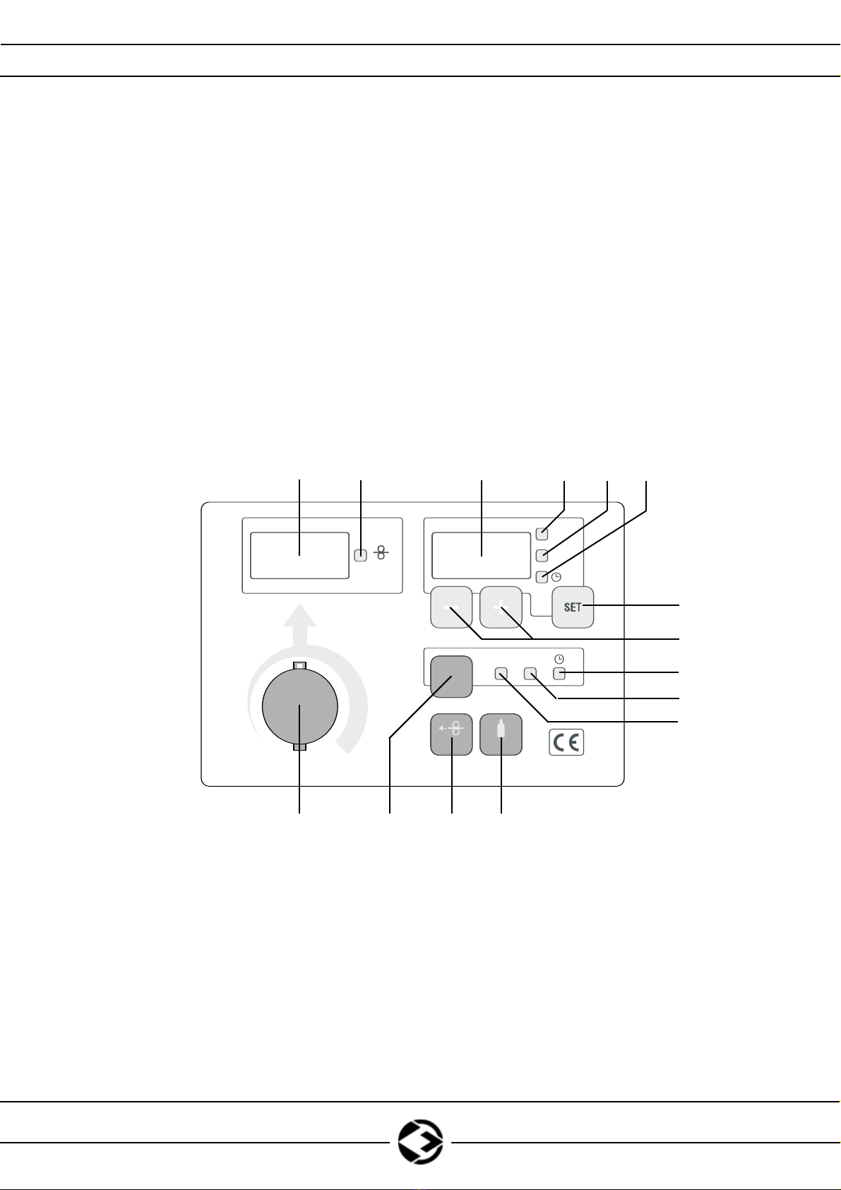
FRONT PANEL
V
SEC
BBT
SOFT
START
A
m/min
2T 4T
CYCLE
INCH TEST
27 28 29 30
33
31 32
34
35
36
37
38394041
Fig. 4

17
Instruction Manual / Betriebsanleitung / Livret d'Instructions / Manuale Istruzioni / Manual de instrucciones FUTURA SERIES
ADJUSTMENTS AND FEATURES ON FUTURA SERIES
Refer to Fig. 4.
POS. 27: Size Display REAL CURRENT and WIRE SPEED (m/min).
POS. 28: WIRE SPEED LED. If it flickers, regulate it using knob (41).
POS. 29: Size Display:
BBT time (Burn Back Time) (See Page 32)
SOFT START (See Page 33)
TIMER (See Page 31)
POS. 30: LED Preset BBT time (Burn Back Time). If it flickers, regulate it using push
button “+”“-”(34).
POS. 31: LED Preset SOFT START. If it flickers, regulate it using push button “+”“-”(34).
POS. 32: LED Preset TIMER. If it flickers, regulate it using push button “+”“-”(34).
POS. 33: Push button to select BBT, SOFT START,TIMER.
POS. 34: Push button for regulation BBT, SOFT START,TIMER.
POS. 35: LED TIMER on.
POS. 36: LED 4 times on.
POS. 37: LED 2 time on.
POS. 38: Test gas push button.
POS. 39: Inch wire push button.
POS. 40: Push button for selection 2T, 4T,TIMER cycle.
POS. 41: WIRE SPEED regulation knob.
Alarms:
Machine is capable to reconise 2 different kind of alarms:
- Over heating alarm, will be visualised on the digital display as ”ALL HFA”.
- Water cooling failure, will be visualised on the digital display as ”ALL CFA”.
In presence of one of these alarms, it is not possible to weld.
-Over heating alarm will disapear soon as the temperature of the machine drops into its stan-
dards limits.
-Water cooling failure will disappear soon as the water level is back to its standards, and the
machine gets turned off and on again.
GB

D
18
Instruction Manual / Betriebsanleitung / Livret d'Instructions / Manuale Istruzioni / Manual de instrucciones FUTURA SERIES
FUNKTIONSEINSTELLUNGEN
Auf Bilder 4.
POS. 27: Display zur Anzeige der eingestellten Parameter SCHWEIßSTROMSTÄRKE und
DRAHTVORSCHUB GESCHWINDIGKEIT (m/min).
POS. 28: LED-ANZEIGE DRAHTVORSCHUB GESCHWINDIGKEIT. Regelung bei Blinken der
Leuchtdiode über den Drehknopf (41).
POS. 29: Display zur Anzeige der eingestellten Parameter:
BBT (Burn Back Time) (Siehe Seite 32).
SOFT START (Siehe Seite 33).
TIMER (Siehe Seite 31).
POS. 30: LED-ANZEIGE Voreinstellung (Preset) der BBT (Burn Back Time).
Regelung bei Blinken der Leuchtdiode über den Tastern “+”e “-”(34).
POS. 31: LED-ANZEIGE Voreinstellung (Preset) der SOFT START.
Regelung bei Blinken der Leuchtdiode über den Tastern “+”e “-”(34).
POS. 32: LED-ANZEIGE Voreinstellung (Preset) der TIMER.
Regelung bei Blinken der Leuchtdiode über den Tastern “+”e “-”(34).
POS. 33: Auswahltaster für BBT, SOFT START,TIMER.
POS. 34: Taster für die Einstellung BBT, SOFT START,TIMER.
POS. 35: LED-Anzeige für TIMER eingeschaltet.
POS. 36: LED -Anzeige für 4-TAKTKREISLAUF eingeschaltet.
POS. 37: LED-Anzeige 2-TAKTKREISLAUF eingeschaltet.
POS. 38: Gas-Test Drucktaste.
POS. 39: DRUCKTASTE zum Drahtvorschub.
POS. 40: Auswahltaster für 2- oder 4-TAKTbetrieb,TIMER.
POS. 41: DRAHTVORSCHUBGESCHWINDIGKEIT-Regelungsknopf.
Fehlermeldungen
Das Gerät ist in der Lage, 2 verschiedene Fehlerarten zu erkennen:
- Überhitzung, auf den Displays durch "ALL HFA" signalisiert.
- Kühlwassermangel, auf den Displays durch "ALL CFA" signalisiert.
Treten diese Fehlermeldungen auf ist Schweißen nicht möglich.
- Die Fehlermeldung "Überhitzung" wird automatisch abgeschaltet, sobald sich das Gerät abkühlt.
- Die Fehlermeldung "Kühlwassermangel" hingegen mußdurch Abschalten des Gerätes zurückgesetzt
werden, nach dem der Wasserstand wiederhergestellt wurde.

F
19
Instruction Manual / Betriebsanleitung / Livret d'Instructions / Manuale Istruzioni / Manual de instrucciones FUTURA SERIES
REGLATIONS ET DISPOSITIVES
Faire référence aux Fig. nr. 4.
POS. 27: Afficheur de visualisation COURANT DE SOUDAGE et VITESSE DU FIL (m/min).
POS. 28: VOYANT VITESSE DU FIL. S’il clignote, régler avec la poignée (41).
POS. 29: Afficheur de visualisation:
temps de BBT (Burn Back Time) (Voir page 32)
SOFT START (Voir page 33)
TIMER (Voir page 31)
POS. 30: VOYANT présélection BBT (Burn Back Time).
S’il clignote, régler avec les boutons “+”et “-”(34).
POS. 31: VOYANT présélection SOFT START. S’il clignote, régler avec les boutons
“+”et “-”(34).
POS. 32: VOYANT présélection TIMER. S’il clignote, régler avec les boutons “+”et “-”(34).
POS. 33: Bouton pour sélection BBT, SOFT START,TIMER.
POS. 34: Bouton pour régulation BBT, SOFT START,TIMER.
POS. 35: VOYANT Indication de TIMER inséré.
POS. 36: VOYANT indication CYCLE 4 TEMPS inséré.
POS. 37: VOYANT indication CYCLE 2 TEMPS inséré.
POS. 38: Bouton test gas.
POS. 39: Bouton d’avancement du fil.
POS. 40: Bouton pour sélection cycle 2T, 4T,TIMER.
POS. 41: Poignée de réglage VITESSE DU FIL.
Alertes
La machine peut relever 2 typer d'alerte.
- alerte de sur-temperature, indique' sur le display comment "ALL HFA".
- alerte manquement eau, indique' sur le display comment "ALL CFA".
Avec ces deux alertes, il n'est pas possible souder.
- L'alerte pour sur-temperature vient deloge' automatiquement avec la rentree dans les limites
anticipees.
- L'alerte pour manquement d'eau doit a' la place etre resette', apres avoir renover le niveau,
eteindantet allumant la machine.

I
20
Instruction Manual / Betriebsanleitung / Livret d'Instructions / Manuale Istruzioni / Manual de instrucciones FUTURA SERIES
REGOLAZIONI E DISPOSITIVI
Fare riferimento alla Fig. 4.
POS. 27: Display per visualizzazione CORRENTE REALE e VELOCITA’FILO (m/min).
POS. 28: LED VELOCITA’FILO. Se lampeggia regolare con la manopola (41).
POS. 29: Display per visualizzazione:
tempo di BBT (Tempo di bruciatura filo) (Vedi pag. 32)
SOFT START (Vedi pag. 33)
TIMER (Vedi pag. 31)
POS. 30: LED selezione BBT (Tempo di bruciatura filo).
Se lampeggia regolare con pulsanti “+”e “-”(34).
POS. 31: LED selezione SOFT START. Se lampeggia regolare con pulsanti “+”e “-”(34).
POS. 32: LED selezione TIMER. Se lampeggia regolare con pulsanti “+”e “-”(34).
POS. 33: Pulsante di selezione BBT, SOFT START,TIMER.
POS. 34: Pulsanti di regolazione BBT, SOFT START,TIMER.
POS. 35: LED TIMER inserito.
POS. 36: LED ciclo 4 tempi inserito.
POS. 37: LED ciclo 2 tempi inserito.
POS. 38: Pulsante test gas.
POS. 39: Pulsante avanzamento filo.
POS. 40: Pulsante di selezione ciclo 2T, 4T,TIMER.
POS. 41: Manopola regolazione VELOCITA’FILO.
Allarmi
La macchina èin grado di rivelare 2 tipi di allarme:
- allarme di sovra temperatura, indicato sul display come ”ALL HFA”.
- allarme mancanza acqua, indicato sul display come ”ALL CFA”.
In presenza di questi allarmi non épossibile saldare.
- L’allarme per sovratemperatura viene rimosso automaticamente con il rientro nei limiti
previsti.
- L’allarme per mancanza acqua deve invece essere resettato, dopo aver ripristinato il livello, spegnen-
do e riaccendendo la macchina.
This manual suits for next models
6
Table of contents
Other Sol Welding Welding System manuals


