Sherman digitec DIGIMIG 2OO HIT User manual

V1.0 8/26/22
USER MANUAL
WELDING SYNERGIC
INVERTER RECTIFIER
DIGIMIG 2OO HIT
Machine Translated by Google

ATTENTION!
WARNING
2. SAFETY
• install current leads with the device switched off, • do not touch
non-insulated parts of the electrode holder, electrode and workpiece at the same time
Prevention of electric shock: • connect the
device to a technically efficient electrical installation with proper protection and zeroing efficiency (additional
protection against electric shock); other devices at the welder's workplace should also be checked and
properly connected to the network,
• VAPOR AND GAS POISONING •
BURNS •
EXPLOSION AND FIRE HAZARDS • NOISE
Any modifications to the rectifier are prohibited and void the warranty.
Damage to the device caused by improper handling will void the warranty.
Due to the continuous technical development of the device, some of its functions may be modified and their
operation may differ in detail from the descriptions in the manual. This is not a device error, but the result of
progress and continuous modification work on the device.
During MIG/MAG electric welding, there are the following risks: • ELECTRIC SHOCK
• NEGATIVE EFFECT OF THE ARC ON
HUMAN EYES AND SKIN
Start-up and operation of the device can only be carried out after reading these Operating Instructions carefully.
Therefore, special precautions must be taken when welding. Before welding, familiarize yourself with
the health and safety regulations in force at the workplace.
deletion,
1. GENERAL NOTES
Welding can endanger the safety of the operator and others in the vicinity.
• It is forbidden to operate the device with the covers removed.
Preventing the negative impact of the electric arc on human eyes and skin: • Use protective
clothing (gloves, apron, leather shoes), • Use protective shields or
visors with a properly selected filter,
Please read this manual before installing and commissioning the device
• know the health and safety rules when handling cylinders and installations with compressed
gas (argon), • know the content of this manual and use the device in accordance with its intended use.
• do not use holders and current leads with damaged insulation, • in
conditions of particular risk of electric shock (work in environments with high humidity and closed tanks) work
with an assistant supporting the welder's work and ensuring safety, wear clothes and gloves with good
insulating properties, • in the event of noticing any irregularities, contact competent persons for correction
Employees operating the device should have the necessary qualifications entitling them to perform welding
works: • they should have electric
welder qualifications in the field of welding in gas shields, • know the health and safety rules when
operating electrical power equipment, such as welding devices and auxiliary equipment powered by electricity,
welded, including the device housing,
2
Machine Translated by Google

• The welding station should be equipped with fire-fighting equipment, • The
welding station should be located at a safe distance from flammable materials.
• Place the charger in a place where it can be easily operated.
It is forbidden to operate the welder in rooms with explosion or fire hazards!
The welding station should be equipped with fire extinguishing equipment.
The hazards and general health and safety rules presented above do not exhaust the issue of welder's work safety, as
they do not take into account the specificity of the workplace. An important supplement to them are workplace health
and safety instructions as well as training and instruction provided by supervisory employees.
Explosion and fire prevention: • It is
forbidden to operate the device and perform welding in rooms with explosion hazard or
• Ensure proper working conditions, ie ensure proper temperature, humidity and ventilation in the place
work. Protect against precipitation outside closed rooms,
All maintenance and repair works may only be carried out by authorized persons, observing the safety
conditions applicable to electrical devices.
arc and spatter,
• Avoid staining clothing with greases and oils that may lead to its ignition.
Burn prevention: • Wear
appropriate protective clothing and footwear to protect against radiation burns
Before starting the device, you should: •
Check the condition of electrical and mechanical connections. It is forbidden to use handles and power cords
with damaged insulation. Improper insulation of the handles and power cords may result in electric shock,
Any modifications of the rectifier on one's own are prohibited and may constitute a deterioration of safety
conditions.
• Blow with fresh air when working in confined spaces (tanks). • Use masks and respirators.
Do not use a power source to thaw frozen pipes.
It is forbidden to remove external covers when the device is connected to the mains.
Prevention of poisoning by vapors and gases emitted during welding from the coating of electrodes
and evaporation
of metals: • Use ventilation devices and extractors installed at workstations with limited exchange
WARNING!
Any repairs to the device may only be made after disconnecting the plug from the power socket.
When the device is connected to the mains, it is forbidden to touch any elements forming the welding current
circuit with bare hands or wet clothing.
absorbing harmful radiation.
air,
fire,
or a welding helmet with a properly selected filter, • know
the content of this manual and use the welder in accordance with its intended use.
• Use protective curtains made of non-combustible materials and properly choose the colors of the walls
Preventing the negative impact of noise: • Use
earplugs or other means of protection against noise, • Warn people
nearby about the danger.
Persons operating the welder should: •
have qualifications for electric welding using the MIG/MAG method, • know
and comply with health and safety regulations applicable to welding work, • use appropriate,
specialized protective equipment: gloves, apron, rubber boots, shield
After finishing work, the device's power cord must be disconnected from the mains.
3
Machine Translated by Google

4
Supply voltage: AC 230V 50Hz
4.1 Welder
Dimensions [mm]:
Level of security:
4. TECHNICAL PARAMETERS
The welding machine is used in closed or roofed rooms, not exposed to direct weather conditions.
Weight (without accessories):
IP21
The device is made in IGBT technology that allows for a significant reduction in the weight and dimensions of the welder and
an increase in efficiency while reducing energy consumption.
Network security 25A
10kg
440x210x370
The device allows you to connect a Spool Gun (SG) type holder with a mini wire feeder and a D100 spool of steel or colored
wire.
Maximum current consumption:
65V
100mm, 200mm
MIG: 33A; MMA: 35A; TIG: 25A
The DIGIMIG 200 HIT synergic welder is used for manual welding of steel and non-ferrous metals. It enables welding with
MMA (covered electrode), TIG and MIG/MAG methods. The MIG/MAG method can be used in manual and synergic modes,
simplifying its operation and allowing the welder to be used by people with less experience and hobbyists. By changing the
polarity, the device allows you to weld using the MIG / MAG method using both standard wires in a protective gas shield and
self-shielding flux-cored wires.
Rated welding current:/duty cycle
Rated no-load voltage Wire spool diameters: MIG: 200A / 45%; MMA: 180A / 60%; TIG: 200A / 60%
3. GENERAL DESCRIPTION
Maximum Power Consumption: MIG: 4.8kVA; MMA: 4.9kVA; TIG: 3.6kVA
Machine Translated by Google

Length:
ARC FORCE (MMA):
If the device is stored or transported in freezing conditions, bring the device to a temperature above
freezing before starting work.
5. PREPARING THE DEVICE FOR WORK
Burning the wire
Cooling gas flow:
Cooling type:
Spot welding time:
E2 appears on the display. After a few minutes, the device cools down to a temperature that allows it to restart
automatically. Do not disconnect the power during this time, as the continuously operating fan cools the internal
heat sinks of the device in order to lower the temperature faster. After restarting, remember to limit the welding
parameters in order to continue continuous operation of the device.
Inductance:
Maximum current carrying capacity:
Overheating protection The IGBT
module is protected against overheating by a protective installation that turns off the power to the welding machine.
The IP protection
degree determines the degree to which the device is resistant to the penetration of solid and water contaminants.
IP21 means that the device is adapted to work in closed rooms.
Wire feed speed:
Handle type:
4.2 MIG gun
welding voltage:
Attention! Heating tests were carried out at ambient air temperature. Duty cycle at 40ºC was determined by
simulation.
Duty Cycle
The duty cycle is based on a 10-minute period. A 45% duty cycle means that after 4.5 minutes of operation, a
5.5-minute break is required. A duty cycle of 60% means that after 6 minutes of operation, a 4-minute break is
required. 100% duty cycle means that the device can work continuously without interruption.
welding current: MIG: 30 - 200A; MMA: 25 - 180A; TIG:15 - 200 A
MIG: 15.5 - 24 V
2.5 - 15 m/min
-10 - +10
0 - 3 s
0 - 10
0 - 10
0 - 10
On / OffVRD (MMA):
4.1.1 Parameter adjustment ranges
200 A (CO2)
gas
10-18 l/min
3 m
HOT START (MMA):
TW-15
5
Machine Translated by Google

3. Polarity Change Plug 4.
Spool Gun Socket 5. "-" Socket
6. Power Switch 7.
Shielding Gas Connector 8. Ground
Clamp 9. Fan 10.
Power Cord
11. Wire Spool Pin 12.
Wire Feeder 13. Spool Gun
Switch
1. MIG gun socket 2. "+"
socket
6
Machine Translated by Google

5.1 Connecting the wires
DCEP
5.1.2 TIG method
5.1.3.1 Welding and brazing in shielding gases
DCEN
5.1.3 MIG and braze welding
The ends of the welding cables should be connected to the sockets (2) and (5) located on the front plate so that
the correct pole for the given electrode is on the electrode holder. The polarity of the welding cables connection
depends on the type of electrode used and is indicated on the packaging of the electrodes (negative polarity
DCEN or positive polarity DCEP). The work clamp must be carefully fastened to the work piece. Connect the plug
of the device to a 230V 50Hz power socket.
The current terminal of the handle should be connected to the socket with negative polarity (5), and the gas hose
to the reducer on the gas cylinder. Connect the positive pole of the source (2) with the welded material using a
cable with a tong clamp. Connect the plug of the device to a 230V 50Hz power socket.
5.1.1 MMA method
For welding with this method, it is necessary to use an additional TIG torch. A 200A gas-cooled torch with a
shielding gas control valve is required.
7
Machine Translated by Google

The current clamp of the torch should be connected to the MIG torch socket (1). The gas line from the reducer
should be led and fixed to the gas connector (7) located on the back wall of the device. Insert the polarity change
plug (3) into the “+” socket (2). Connect the negative pole of the source (5) with the welded material using a
cable with a clamp. Connect the plug of the device to a 230V 50Hz power socket.
The current clamp of the torch should be connected to the MIG torch socket (1). Insert the polarity change plug
(3) into the “+” socket (2). Connect the negative pole of the source (5) with the welded material using a cable
with a clamp. Connect the plug of the device to a 230V 50Hz power socket.
5.1.3.3 Welding with a Spool Gun (optional)
5.1.3.2 Welding with self-shielding steel wire
Set the switch (13) inside the feeder chamber to the Spool Gun position.
The current clamp of the torch should be connected to the MIG torch socket (1). Insert the polarity change plug
(3) into the "-" socket (5). Connect the positive pole of the source (2) with the welded material using a cable with
a tong clamp. Connect the plug of the device to a 230V 50Hz power socket.
8
Machine Translated by Google

5. Check that the drive rollers are suitable for the type and diameter of the wire. Install the correct roll if
necessary. Use rolls with V-grooves for steel wires and U-grooves for aluminum wires.
1. The device should only be used in a single-phase power supply system,
5.3 Connection to the mains
4. Release the feed roller pressure.
3. Secure the spool against falling.
5. Unscrew the cylinder and reducer valve.
4. Connect the reducer hose with the gas connector (7) on the rear wall of the welder.
2. Place the spool of filler wire on the mandrel.
11. Adjust the pressure of the feed roller by turning the pressure knob. Too little clamping force will result in
slipping of the drive roller, too high clamping force will increase feeding resistance, which may lead to wire
deformation and damage to the feeder.
10. When the wire appears in the outlet of the gun, release the button and screw on the contact tip.
3. Install the regulator on the cylinder.
1. Open the side housing cover.
5.4 Fitting the wire electrode spool
2. Open the cylinder valve for a moment to remove any impurities.
9. Unscrew the current tip from the holder, turn on the power supply of the welder and pull the wire into the
welder's holder by pressing the button in the handle of the welding torch or using the wire feed button (C)
on the device panel.
8. Press the wire into the grooves of the drive roller.
1. Secure the cylinder and prevent it from tipping over.
3. The device is equipped with a power cord and plug. Before applying power, make sure that the power
switch (6) is in the OFF position.
2. The DIGIMIG 200 HIT inverter rectifier is adapted to work with a 230V50 Hz mains protected with 25 A slow-
acting fuses. The power supply should be stable, without voltage drops.
5.2 Shielding gas connection
7. Insert the wire through the drive roller of the feeder into the holder.
three-wire, with a grounded neutral point.
6. Debur the tip of the electrode wire.
9
Machine Translated by Google

D200 spool
Depending on the type of material to be welded and the diameter of the electrode wire, attach the appropriate
contact tip and wire guide insert to the MIG gun.
D100 spool
5.5 Preparing the MIG gun for work
For steel welding, use steel contact tips and a steel insert. In the case of aluminum welding, use aluminum
welding contact tips and a Teflon insert.
10
Machine Translated by Google

VRD function
SPt
india bbt
HOT START function
ARC FORCE function
During MIG/MAG welding, the display shows the welding voltage and the symbols of adjustable functions and parameters
as well as error codes.
A - Welding voltage display
Spot welding time
6.1 Front panel
Burning the wire
Inductance
6. OPERATION
The device has a quick wire feed function. Pressing the button (C) causes the wire to be ejected quickly, allowing it to be
easily inserted into the holder.
VRD
HS
5.5.1 Fast Wire Inch
AFc
11
Machine Translated by Google

The display shows the welding current / wire feed speed and the values of adjustable functions and
parameters.
By pressing the button for a few seconds, the electrode wire is rapidly advanced. It can be used when setting
up a spool of wire in order to quickly insert it into the welding gun.
Button active only during MIG/MAG welding. Used to select the diameter of the electrode wire. Selection of
the appropriate diameter is confirmed by lighting of the control diode.
B - Welding current display
C - Fast wire feed button
D - Electrode wire diameter selection button
12
Machine Translated by Google

Allows you to select the source control mode. The selection of the appropriate mode is signaled by the lighting of
the appropriate diode.
E - Source operation control button
Pressing and releasing the welding torch button will ignite the arc and start welding.
When the button is pressed and released again, the arc will be extinguished.
Pressing the welding torch button will ignite the arc and start welding. The arc will extinguish when the button is
released.
The button is active only during MIG/MAG welding in manual and synergic modes.
13
Machine Translated by Google

Pressing the button causes the transition to adjustment of other parameters and functions. The selection of a
parameter or function is signaled by lighting up the appropriate diode under one of the displays.
F - Multifunction knob.
The knob is used to adjust welding functions and parameters. During MIG/MAG welding in manual mode, it is
used to adjust the wire feed speed. When welding in the synergic mode and in the MMA and TIG methods, it is
used to adjust the welding current.
Spot welding. Pressing the welding torch button will ignite the arc. After the time SPt has elapsed, the arc will be
extinguished. Releasing the gun button early will extinguish the arc immediately.
G - Welding voltage knob
14
Machine Translated by Google

MIX
15
FLUX
CO2
I - Welding method selection button
Knob active only during MIG/MAG welding. In manual mode, it is used to adjust the welding voltage. In the
synergic mode, it is used to correct the welding voltage selected by the synergic program.
- welding of carbon steels in a CO2 shield.
Selection of the appropriate mode is confirmed by lighting of the control diode.
- welding of aluminum in an argon shield.
18% CO2.
Button active only during MIG/MAG welding Used to select the material to be welded.
- welding of carbon steels in the shielding of the Ar/ CO2 mixture. The recommended mix ratio is 82% Ar
H - Welded material and shielding gas selection button
– steel welding with self-shielding wire (without gas shield)
AL
Machine Translated by Google

TIG
MMA
MIG
SHUTTER SYNC
Adjustment range
- TIG welding.
VRD
ArcForce
- MMA welding (covered electrode).
Symbolparameter / function
Urd
- MIG/MAG welding with synergic settings. The device selects the welding parameters depending on the
selected type and thickness of the material. These parameters can be changed by the user.
After selecting the MMA method, it is possible to adjust the parameters according to the table below.
AFc
HS
- MIG welding with manual selection of settings.
7.1 MMA method
HOT START function
The HOT START function is popularly called a hot start. It works when the arc is struck, causing a temporary increase
in the welding current above the value set by the welder. HOT START is designed to prevent the electrode from sticking
to the material and is a great help when striking the arc. In the case of welding small elements, it is recommended to
disable this function, as it may cause burnout of the welded material.
7. PARAMETER SETTINGS
0-10HotStart
The button is active only during MIG.MAG welding. Pressing and
holding the button will cause the flow of shielding gas, releasing it will stop the flow of gas.
ARC FORCE function
The ARC FORCE function allows you to adjust the dynamics of the welding arc. Shortening the arc length is
accompanied by an increase in the welding current, which stabilizes the arc. Decreasing the value gives a soft arc and
shallower depth of penetration, while increasing the value causes deeper penetration and the possibility of short arc
welding. With a high value of the ARC FORCE function, you can weld while keeping the arc length to a minimum and
the electrode melting speed high
Welding current
The button is used to select the welding method. Selection of the appropriate mode is confirmed by lighting of the
control diode.
VRD function
The VRD function lowers the no-load voltage. The correct voltage value is only restored just before the arc is struck.
This minimizes the risk of electric shock, but in some cases it may make it difficult to strike the arc.
0-10
on/off
J - Protective gas button
25 - 180A
16
Machine Translated by Google

manual MIG
Welding voltage correction in synergy modes After setting
the welding current in synergic modes, it is possible to correct the welding voltage. After setting the welding current with the
knob (F), the welding voltage can be corrected with the knob (G).
aluminum (ER5356)
Wire feed speed Wire diameter
FLUX
Adjustment range
-10 ~ +10
After selecting the TIG method, it is only possible to adjust the welding current.
Wire feed speed
Burning the wire
Wire diameter / welding
current
Mode
Depending on the selected control mode and welding method, it is possible to adjust the parameters according to the table
below.
CO2
During MIG welding, the device can operate in synergic (SYN MIG) and manual (MIG) modes. The synergic mode allows
you to select welding parameters for less experienced users. In this mode, the device automatically selects the welding
current and wire feed speed depending on the type of material being welded and the diameter of the electrode wire. It is
possible to correct the welding voltage.
material / gas
Inductance
0 - 10
MIX
Wire feed speed Wire diameter
FLUX
Adjustment range
1.0 / 0.9 / 0.8 / 0.6 mm
2.5 - 15 m/min
1.0 / 0.9 / 0.8 / 0.6 mm
2.5 - 15 m/min
1.0 / 0.9 / 0.8 mm
2.5 - 15 m/min
1.0 mm
2.5 - 15 m/min
1.0 mm / 60 – 200 A
0.9 mm / 60 – 200 A
0.8 mm / 30 – 200 A
0.6 mm / 30 – 200 A
1.0 mm / 60 – 200 A
0.9 mm / 60 – 200 A
0.8 mm / 30 – 200 A
0.6 mm / 30 – 200A
1.0mm / 58 – 200A
0.9mm / 58 – 200A
0.8mm / 35 – 200A
MIX
indium
7.2 TIG method
In addition, during MIG/MAG welding, the following buttons are active:
Manual and
synergic MIG
1.0mm / 50 - 200A
Wire feed speed Wire diameter
AL (ER5356)
SPt
- fast wire feed
Mode
7.3 MIG AND SYN MIG
Wire diameter / welding
current
Parameter
Spot welding time
Symbol
The manual mode allows the user to select the welding voltage and wire feed speed depending on the needs.
CO2
Synergic MIG
0 - 3 sec
- test gas flow
Wire diameter / welding
current
Wire diameter / welding
current
bbt
Wire
diameter parameter
17
Machine Translated by Google

FLUX
Copper-based binders are most commonly used as filler material. These are wires marked as CuSi3 or SG -CuAl.
0.6/0.8/0.9/1.0
carbon steel
Changing the inductance value also reduces the amount of welding spatter during welding in a CO2 shield. The higher the
value of the inductance (+) the less spatter, when the value is negative (-), the greater the amount of spatter. The optimal
setting of the inductance value depends on several factors and may differ from the standard recommendations, so it should
be selected experimentally during welding tests.
1.0
-
8. WELDING OF ALUMINUM ALLOYS
Argon
The welder has built-in synergic programs for selected materials, wire diameters and shielding gases in accordance with the
table below:
Designation
Aluminum welding is not a simple activity, it requires the welder's experience, knowledge and adherence to certain practices
that will facilitate the execution of welds on aluminum elements. In the synergic program, the device selects the output
parameters for the appropriate grade of materials and types of wires.
AL
0.6/0.8/0.9/1.0
Using three welding parameters, set the optimal set to obtain the right weld. When selecting parameters, choose low voltages
and high wire feed speeds. It is recommended to use argon as the shielding gas, but the use of a mixture of argon and CO2
(82/18) also gives good results. Due to the required shape of the weld, the inductance should be selected experimentally
depending on the thickness and type of the welded material.
MIX
In addition, depending on the working conditions, you can set the inductance value, which affects the shape of the weld, the
depth of penetration and the amount of spatter during welding. It should be taken into account that the recommended
welding parameters in the synergic mode apply to typical welding consumables from the selected group and the
recommended shielding gases. When welding different alloy materials, the operating parameters may not be optimal
and require adjustment of the settings. For this reason, the synergic mode should not be treated as a universal
parameterization proposal, but as a starting point for precise adjustment of settings.
First of all, you should remember about a few important things that significantly affect the appearance of the weld and affect
the correct course of the welding process.
Inductance adjustment
Inductance adjustment enables optimization of the arc characteristics depending on the thickness of the workpiece and the
welding method and conditions. The function is useful during MIG/MAG welding of thin elements, preventing their burn-
through, and during braze welding of galvanized elements.
It is recommended to use a handle not longer than 3 m equipped with a Teflon insert.
0.8/0.9/1.0 Ar+CO2 (82/18)
Device: •
Make sure that the feed rolls are designed to work with aluminum: the groove is U-shaped and dedicated to the correct
diameter of the welding wire. Using the wrong rollers will cause deformation of the wire and problems in the welding
process.
Material
Adjustment of this parameter also enables braze welding of thin (up to 3 mm) galvanized elements with wires made of CuSi3
copper alloy in pure argon shield or in some cases Ar/CO2 mixture in ratio (82/18).
Aluminum (ER 5356)
In synergic mode, you can select a program for aluminum welding. The program has been selected for welding with AlMg5
wire type ER 5356, which is suitable for welding all types of structures and sections.
Depending on the needs, appropriate voltage and inductance corrections should be made to obtain the desired effect.
Shielding gas -
recommended
• Use high grade argon: 4.8 and above recommended
Manual MIG mode, i.e. manual selection of parameters, is especially useful for brazing.
Before starting welding work on aluminum components, the following steps must be taken:
Wire diameter
CO2CO2
18
Machine Translated by Google

19
finished work.
next use.
• Aluminum welding stations should be vacuumed with industrial vacuum cleaners once a day, after
in original packaging.
• The wire does not need to be stored in air-conditioned rooms, it is best to store it in low humidity conditions.
Do not soak the wire in water. • If a wire that is relatively cold is brought into a room on a hot,
humid day and immediately opened, it is possible that the humid air will contaminate the wire. Therefore, if
the wire is stored in an air-conditioned room, remember not to unpack the wire until it has warmed up
and adapted to the ambient temperature. • After finishing work, the wire should be removed from the
feeder and secured in a plastic bag for
1. Open the valve on the TIG torch so that the shielding gas flows out.
Workplace: • Pay
attention to the proper preparation of the welding work place: the hall should be clean, well ventilated
and the air humidity should be kept low. The presence of iron oxide dust or dust from electro-
air gouging of steel is unacceptable.
• Make sure the contact tip is the correct size and is designed for aluminum wire. • Consider replacing part
of the wire guide in the feeder with a Teflon version that improves wire feeding like a welding gun.
• Aluminum welding wire should be stored in a clean, dry environment, preferably
9.2 TIG method
Using steel components used to feed steel wire will cause feeding problems.
Proper storage of the welding wire
2. In the case of arc initiation with electrodes whose coating, after solidification, forms a non-conductive
slag, initially clean the tip of the electrode by hitting it several times on a hard surface until metallic
contact with the welded material is obtained.
• Make sure the handle is equipped with a Teflon guide insert designed for aluminum.
• After proper surface preparation, the welding process should be carried out as soon as possible. •
If a part must remain unwelded for an extended period of time, protect it with brown kraft paper and tape it.
9.1 MMA method
1. Touch the electrode to the workpiece, briefly rub it and tear it off.
cause a feeding problem.
Material preparation:
• The welding area should be cleaned and degreased just before welding,
• Aluminum elements should be degreased by wiping with a clean cloth soaked in a degreasing agent, eg
acetone (Alcohol is not a good degreasing agent, we advise against using it when cleaning aluminum).
• Remove heavy oxide residues before welding.
Normally, this is done manually or mechanically with a steel wire brush. If the material has become heavily
soiled, it may be necessary to use a grinder.
9. ARC INITIATION
• Make sure the feed rolls are not too tight. Excessive wire tension can
• Welders' clothes should be clean, gloves should not be greasy.
For welding aluminum alloys, pure argon of high quality class, recommended not less than 4.8, should be used
as a shielding gas. The gas flow should be selected according to the thickness and welding speed. Good
welding results are achieved when the process direction is counterclockwise.
Machine Translated by Google

20
Welding
speed
(cm/min)
5.0
Free
electrode
outlet (mm)
4.0
Gas flow (l/min)
Thickness (mm)
gap (mm)
3.2
Shielding gas
flow (l/min)
ÿVÿ
welding
voltage
Electrode wire
diameter (mm)
Electrode diameter
(mm) Welding current (A)
Welding current
2.5
Welding current
Wire
diameter(mm) (AND)
Electrode diameter
Sheet
thickness(mmÿ
LowweldingspeedbuttweldHighweldingspeed
1.0
10ÿ15
60ÿ70 16ÿ16.5 50ÿ60
3.0
130
120
1.6
180
200
220
1.2
15
10.3 MIG method
110 - 140A
10
10. TABLE OF RECOMMENDED PARAMETER VALUES
1.0,1.2
2.0
0
1.6
15ÿ20
260
10ÿ15
10
19ÿ5
21
23
17
2.0
10
0.8,0.9
0.8,0.9
0.8,0.9
1.0,1.2
1.0,1.2
1.0,1.2
1.2ÿ1.6 300ÿ340 32ÿ34 45ÿ50
1.0ÿ1.2 140ÿ150 20ÿ21 45ÿ50 10ÿ15
10.1 MMA method
95ÿ105 17ÿ18 45ÿ50
2.4
15
1.2
2. Lightly touch the electrode to the workpiece, detach the electrode from the workpiece by tilting the handle so that the gas nozzle
touches the workpiece.
1.6
26
10ÿ15
0
2.3
130
100
120
35 - 45
17ÿ5
130
170 - 220A
15
0
1.0ÿ1.5 160ÿ180 22ÿ23 45ÿ50
1.2
4 - 6
15
10
3. After striking the arc, straighten the handle and start welding.
2.0 - 2.4
120
10ÿ15
10
15
15
75ÿ85 17ÿ17.5 50ÿ60
40 - 70
3.2
18ÿ5 10
0.8
1.2ÿ1.6 300ÿ340 32ÿ34 45ÿ50
0
15
1.2
5 - 8
15
0ÿ0.5
9.3 MIG method
15
2.4 - 3.2
15
15
20
10
15
50 - 85
4.5
10
1.0
15
0.8
230 - 280A
1.2ÿ1.6 220ÿ260 24ÿ26 45ÿ50
1.2
0
6 - 8
0.8,0.9
0.8,0.9
0.8,0.9
1.0,1.2
1.0,1.2
1.0,1.2
110ÿ120 18ÿ19 45ÿ50
1. Bring the holder closer to the parts to be welded so that the distance between the nozzle and the parts to be welded is equal
0
1.0
20
3.2
15ÿ20
0.8,0.9
80 - 130
1.5
10ÿ15
1.6
2.0
2.3
130
1.0
100
10.2 TIG method
0.8
15
70 - 100A
8 – 10
10
1.6
was about 10 mm.
80ÿ90 16ÿ16.5 50ÿ60
1.2
15ÿ20
0
120 - 150
10ÿ15
2.0
0
0
0
10
1.2
1101.0
1.2ÿ1.6 220ÿ260 24ÿ26 45ÿ50
10-12
2. Press the button on the welding gun and start welding.
0.5ÿ1.0 120ÿ130 19ÿ19.5 45ÿ50
1.6
10
0
15ÿ20
Machine Translated by Google
Table of contents
Other Sherman digitec Welding System manuals
Sherman digitec
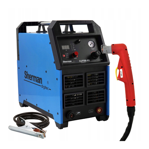
Sherman digitec Cutter 110 User manual
Sherman digitec
Sherman digitec DIGITIG PULSE AC/DC 200GD User manual
Sherman digitec
Sherman digitec DIGITIG 200DC MULTIPRO User manual
Sherman digitec
Sherman digitec ACDC TIG 315GD User manual
Sherman digitec
Sherman digitec DIGIMIG 2OO PULSE User manual
Sherman digitec
Sherman digitec DIGITIG 200AC / DC MULTIPRO User manual
