Sol GreenWay GRNWY-50 Installation instructions

GreenWay™
Solar LED Path and Trail Lighting System
Installation and
Owner’s Manual
2 GreenWay™ installation & operation manual 0410 MKTG-IM-GREEN-002
IMPORTANT SAFETY INSTRUCTIONS - SAVE THESE INSTRUCTIONS
This manual contains important instructions for the SOL GreenWay™ Series that shall
be followed during installation and maintenance of the charge controller.
The SOL GreenWay™ is a patented, off-grid, standalone, solar-powered lighting system. Years of
engineering, development, and testing ensure that this system meets or exceeds all performance and
reliability specifications. Every system that leaves our factory has been quality control tested and inspected to
assure you of an easy installation and highly dependable performance. All mechanical fittings and electrical
connections are designed for simple and reliable installation. The system is ready for use immediately after
the components are mounted and the plug and play connectors are joined.
IMPORTANT NOTES AND WARNINGS
This installation and instruction manual provides installation, operation, and maintenance instructions for
the SOL GreenWay™ solar LED lighting system. The entire contents of this manual should be thoroughly
reviewed and understood prior to installing this equipment. Do not discard this manual. It contains complete
maintenance instructions, a troubleshooting chart, and a spare parts list. To insure proper operation of this
equipment, it is important that the equipment be utilized for its intended use. Any use of this equipment for
purposes other than those intended will void all warranties.
Installation and/or troubleshooting should be performed only by qualified personnel. Follow local
codes at all times during installation of the GreenWay™.
Be very careful when working with batteries.
Do not allow bare ends of the wires to touch each other or grounded metal parts while connected
to the controller. This will damage the controller.
CONTENTS
Section 1 Site Selection and System Overview 3
Section 2 Parts List 4
Section 3 Pole Preparation and Attaching PV Array 5
Section 4 Assembling Components and Riveting Arm Assembly 6
Section 5 Mounting Battery Box and Installing Battery 7
Section 6 Installing Luminaire and System Wiring 7-8
Section 7 Controller 9-11
Section 8 Operation, Maintenance and Troubleshooting 12-15
Section 9 Warranty 16
Operational Principles
The SOL GreenWay™ solar LED lighting system is designed to provide reliable operation and illumination
all year. The solar array (the photovoltaic panel, or PV panels) re-charges the battery each day, replacing
energy that was used during the previous evening so that illumination can again be provided during the
following evening. The system is designed with a reserve, so that regular illumination will continue to be
provided during periods of rainy or cloudy weather. The controller monitors battery condition and will shut off
illumination if the battery charge drops below a specified level. This may occur if there is a prolonged rainy or
cloudy weather or if the solar array is shaded during part of the day. The controller automatically restarts the
system when the condition is corrected and the battery charge returns to the specified level, protecting the
batteries.

3 GreenWay™ installation & operation manual 0410 MKTG-IM-GREEN-002
Site Selection and Preparation
Locate and install the PV panels in an area where the PV panels can face the equator (due south in the
Northern hemisphere) and not shaded by trees, poles, buildings, or other objects during the day (Figure 1).
Do not locate in an area where there is
excessive ambient or reflected light at night
which may simulate daylight and cause the
system controller to turn off the system.
Installing in a location where the solar
panels are shaded during part of the day will
prevent the solar panel from fully charging
the battery, reducing the hours of nighttime
illumination and possibly damaging the
battery. If installed near a tree, check the
tree branches every three months and trim
when needed.
Installation of the solar light system and
pole must comply structural engineering
requirements for local and national codes.
FIGURE 1 LOCATING AND POSITIONING THE PV PANELS
System Overview
Pole
PV Assembly
PV Modules- Always facing EQUATOR (South in
Northern Hemisphere)
LED Luminaire
Battery Enclosure (B.E.)
Arm Assembly
FIGURE 2 SYSTEM OVERVIEW
Holes for Luminaire install
must face DOWN
Battery Battery Box
Cover
Controller

4 GreenWay™ installation & operation manual 0410 MKTG-IM-GREEN-002
DESCRIPTION PART NUMBER GRNWY-50 GRNWY-80 GRNWY-125
Pole 302012-007DB 1 1 1
Solar Panel Assembly 30040-001 1
Solar Panel Assembly 30080-003 1
Solar Panel Assembly 33172-010 1
Solar Panel Mount 15 Deg
or 45 Degrees
302012-101*
302012-103*
1
1
1
Arm Assembly 302012-201 1 1 1
Battery 86008-001 1 1 1
Battery Box 202721-200 1 1 1
Solar Panel Harness 855200-031 1 1 1
Battery Harness 855200-002 1 1 1
LED Harness 805000-004 1 1 1
aiSUN™ Controller 855101-200 1 1 1
aiSUN™ 56L Single Battery
Harness
855200-010
Solar Panel Assembly Mounting
Hardware
GWHP-PV 4 4 4
Battery Box Mounting Hardware GWHP-BB 4 4 4
Drive Rivets DR375X.50GR 11 11 11
Fixture Assembly:
Ascot
Shoebox (1Q)
781001-100
781001-200
1 1 1
Parts List
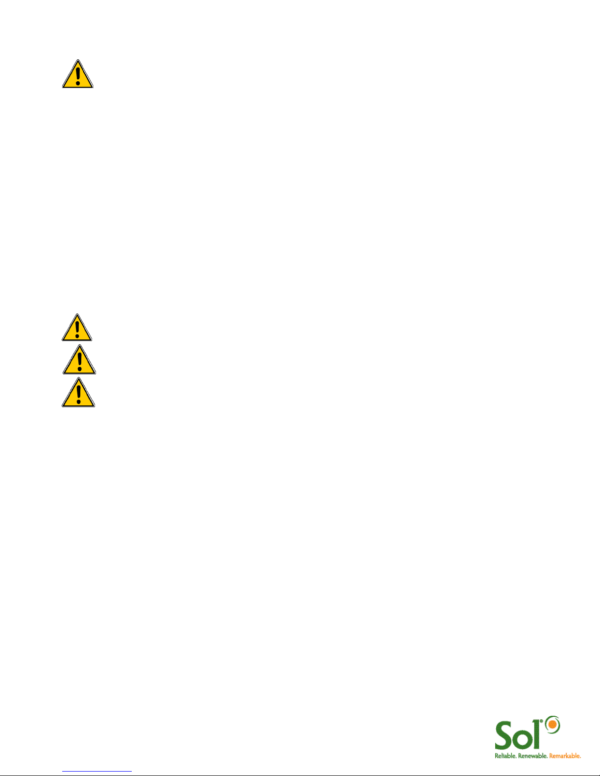
Pole Preparation and Installation
Four holes must be drilled at the top of the pole. This should be done before the pole is set and anchored.
Drill two equally-spaced 0.125-inch (3.2 mm) pilot holes 1 inch (2.5 cm) below the top of the pole, as shown
in Figure 3. Drill two additional equally-spaced 0.125-inch (3.2 mm) pilot holes 4 inches (10.2 cm) below the
top of the pole, as shown in Figure 3. Position the holes 90 degrees from the holes drilled in previous step.
FIGURE 3 DRILLING 4 HOLES AT TOP OF POLE
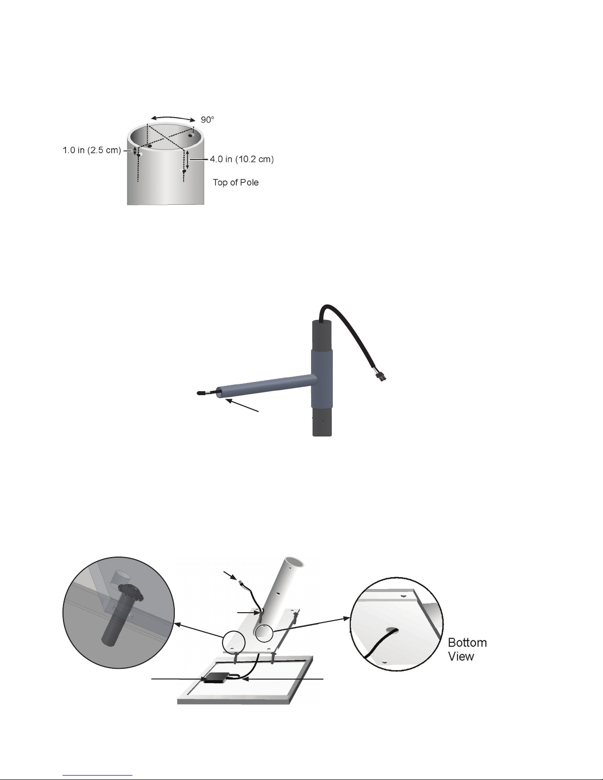
FIGURE 4 ROUTING LUMINAIRE LOAD CABLE
Routing Luminaire Load Cable Through Arm Assembly
Insert the male end of the luminaire load cable (with cord grip in plastic bag) into the fixture end of the arm. Slide the
luminaire load cable through the arm assembly until the connector plug emerges from pipe end of the arm assembly,
opposite side of luminaire install holes (Figure 4).
FIGURE 5 ATTACHING PV ASSEMBLY TO PV MODULE
Attaching the PV Module to the PV Mount
Lay the PV module upside down on a protected surface (cardboard shipping carton can be used) and
position the PV mount over the PV module so that the hole and grommet on the side of the pipe face the
PV module junction box. Route the PV cable in through the center hole and out through the side of the PV
mount. Fasten the PV mount to the PV module using the 4x bolts and washers provided (Figure 5).
Pole Anchoring
It is imperative that the pole is properly anchored.
Standard pole anchoring methods may be used,
providing they meet the engineering requirements
for EPA and weight of the system you have
purchased.
Holes for Luminaire install
must face DOWN
Junction Box
Hole & Grommet
MC Connectors
to PV Module
PV Module Cable

6 GreenWay™ installation & operation manual 0410 MKTG-IM-GREEN-002
Arm Assembly
Assembling the Components
After the pole has been set and anchored, slide the arm assembly into the top of the pole (Figure 6a). Route the PV
load cable through bottom of the solar panel assembly pipe and out through the grommet and hole on the front of the
pipe (Figure 6b). Place the solar panel assembly on the top of the arm assembly. Swing the arm assembly so that the
light fixture (which will be attached to the end of the arm) is in the desired position (Figure 6c)
FIGURE 6 ASSEMBLING ARM ASSEMBLY AND PV ASSEMBLY TO POLE
Arm Assembly
Pole
Luminaire Load
Cable
Luminaire Load
Cable
PV Module Cable
Equator (Due South in
Northern Hemisphere)
PV Assembly
abc
Riveting the Arm Assembly to the Pole and Solar Panel Assembly to the Arm Assembly
Verify that the arm is positioned so that the light fixture (which will be attached to the end of the arm) is in the desired
orientation. Using one of the pilot holes at the upper end of the pole as a guide, drill one rivet hole using a U.S. “W”
gauge (0.386-inch) drill bit (or use a 25/64-inch drill bit if “W” gauge not available). Drill through the pilot hole and then
through the arm assembly stock beneath the pilot hole (drill & rivet one pilot hole at a time). Place a drive rivet in the rivet
hole (Figure 7a). Pound the drive rivet into the hole (Figure 7b) until the head of the drive rivet is tight against the side of
the pole (Figure 17c). Install the three remaining drive rivets in the arm assembly.
Verify that the solar panel is positioned so that the solar panel is facing due south. Using one of the pilot holes at the
lower end of the solar panel assembly as a guide, drill one rivet hole using a U.S. “W” gauge (0.386-inch) drill bit. Drill
and rivot one pilot hole at a time following same instructions used for the arm assembly.
FIGURE 7 RIVETING THE ARM ASSEMBLY AND SOLAR PANEL ASSEMBLY
b c
Drill holes
in pilot
holes
(4 places)
a
7 GreenWay™ installation & operation manual 0410 MKTG-IM-GREEN-002
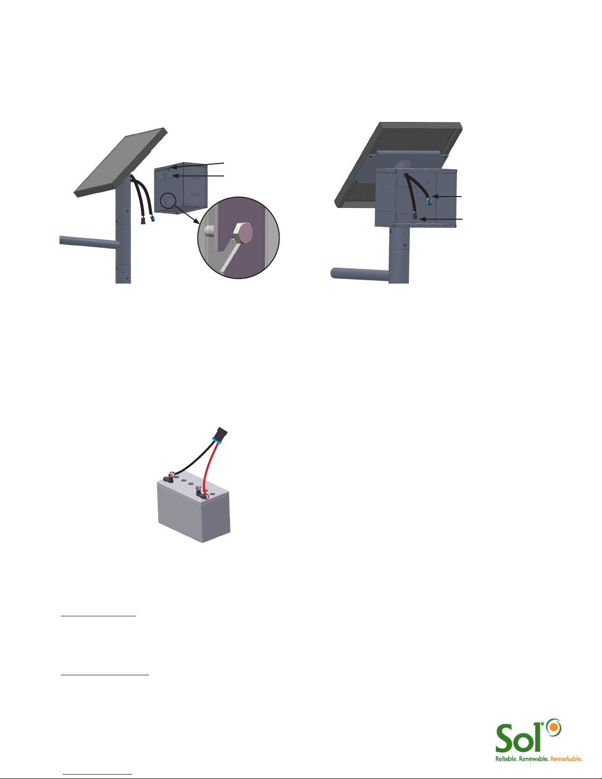
Mounting Battery Enclosure and Routing PV and Luminaire Cables
Route the ends of the solar PV cable and the Luminaire cable through the hole and grommet at the back of the battery
box, as shown in Figure 9. Loosely fasten the brackets at the back of the battery box to the pipe of the solar panel
mounting, using four 1/4”–20 x 1/2” hex head bolts. Securely tighten each bolt. Position the cables so they extend
inside the battery box at least 12 inches (30.5 cm).
FIGURE 9 MOUNTING BATTERY BOX FIGURE 10 ROUTING CABLES
PV Cable from PV Array
Luminaire cable from LED
Luminaire
Hole and Grommet
Bracket
Installing the Battery/Batteries
Loosely connect the battery harness to the battery terminals. When connecting the battery, connect the
positive terminal first (Red +). Protect the free (unconnected) ends of the battery harness from touching other
metal parts so they will not accidentally cause a short. Tighten the connection on both terminals. Place the
battery in the battery box. Connect the battery harness to the single aiSUN™ harness as shown in Figure 11.
Battery Harness - one for each battery
Black (-)Red (+)
Gel Cell 100 Ah
NRGLife™ Battery
FIGURE 11 BATTERY AND BATTERY HARNESS
Installing Luminaire
For Ascot Fixture:
Connect the connector from the LED luminaire to the connector at the end of the luminiare load cable.
Slide the LED fixture onto the arm. Adjust the LED fixture for the desired tilt. Secure the LED fixture to the arm using the
socket head bolts (Figure 12).
For Shoebox Fixture:
Loosen the set screws that secure the slip fitter. Plug LED luminaire connectors together. Slip fixture over pipe (guide
excess wires into pole). Secure set screws. To adjust angle remove circular cover using Phillips screwdriver. Using a
socket wrench, loosen bolt to adjust angle to desired angle. Tighten bolt and replace cover (Figure 13).
8 GreenWay™ installation & operation manual 0410 MKTG-IM-GREEN-002
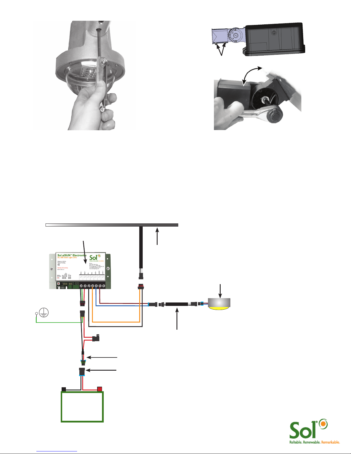
System Wiring Diagram
All solar light systems with aiSUN™ controllers ship with Clik™ together wiring harnesses. This
eliminates field wiring and splicing. Use the wiring diagrams below for connecting your solar light
system. Note: includes a field replaceable fuse.
FIGURE 14 WIRING DIAGRAM
Battery 1
Black (-) (+) Red
Battery Harness
aiSUN™ Controller
PV Module
LED Luminaire
Brown (+)
Blue (-)
Luminaire Load
Cable
Black (-) Red (+)
Green-
Ground
aiSUN™ Single Harness
Black (+)
Orange (-)
This lamp (LED) is in excess of the Exempt Risk Group defined in IEC 62471:2006-07. This lamp (LED) has been found to be in the Risk
Group 2 classification at an exposure distance of 20 cm or less from the glass surface of the lamp. Care should be taken to avoid exposure
when operating and installing this lamp.
FIGURE 13 MOUNTING SHOEBOX
Set screws
FIGURE 12 MOUNTING ASCOT
9 GreenWay™ installation & operation manual 0410 MKTG-IM-GREEN-002
aiSUN™ Solar Light CPU
This guide describes how to complete the assembly of your light system when it is outfitted with an aiSUN™
CPU. aiSUN™ features & troubleshooting information is provided.
What does the aiSUN™ CPU do?
aiSUN™ is a unique solar charging controller and LED luminaire controller packaged into one intelligent solar
light CPU. aiSUN™ performs the following 2 tasks:
1. Charges batteries: Electricity generated by the PV module is modulated and controlled by the aiSUN™
to properly and safely charge the solar light’s NRGLife™ batteries.
2. Operates the LED Luminaire: Using a factory-installed configuration, aiSUN™ turns on the LED luminaire
after sunset and turns off the luminaire before sunrise as configured per each location. This includes
dimming and response to motion detection in some configurations.
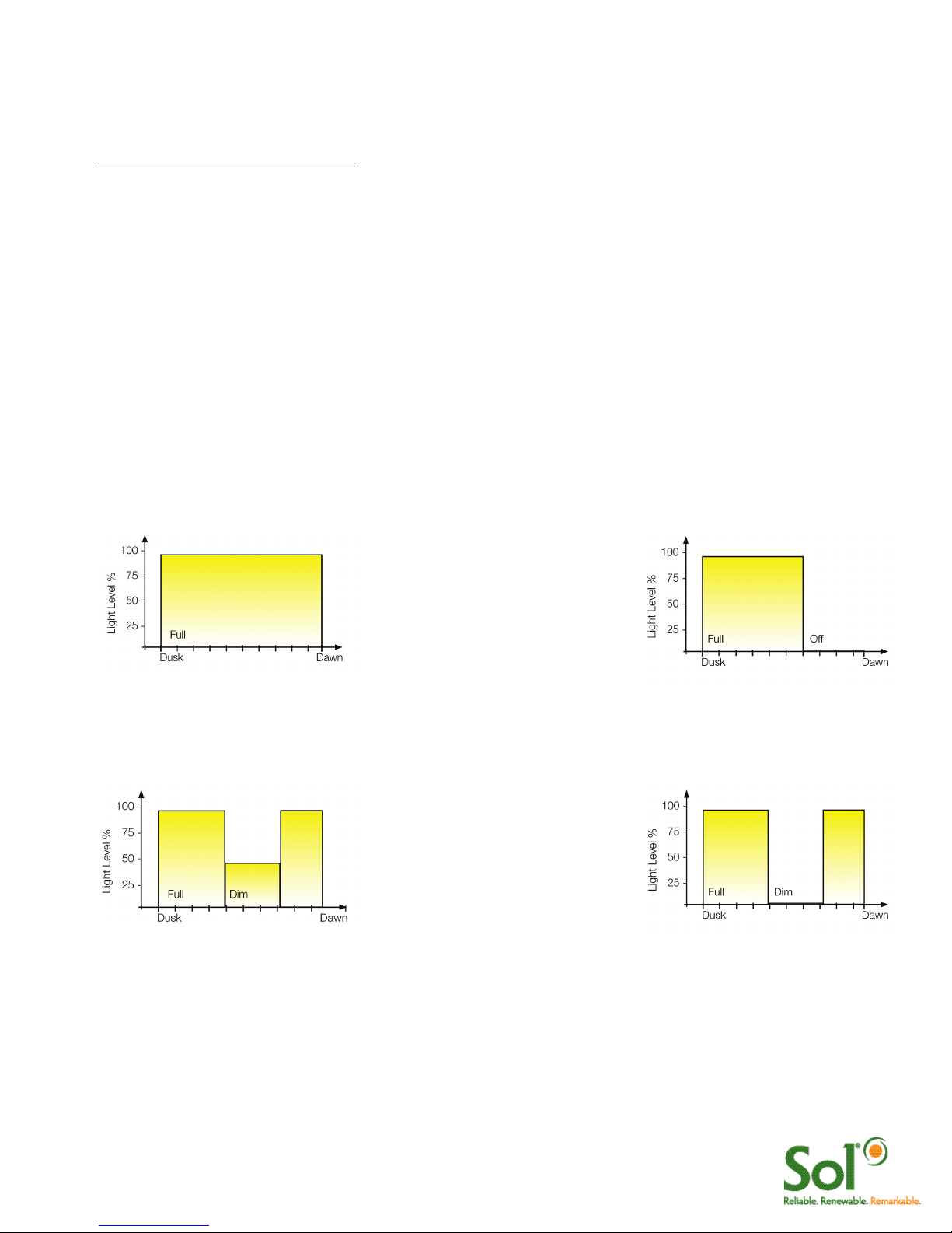
aiSUN™ is factory configured for your location. No adjustments are required. Lights are programmed to run
in one several operating modes.
Operating mode is shown on the unit label as: HH.LLL.LLL.HH.LLL
(1) (2) (3)
(1) light setting after sunset
(2) light setting in the middle of the night
(3) light setting before sunrise
where: HH is the number of hours at full intensity and LLL is the light intensity in percentage
Dusk to Dawn unit label reads:
DD.100.000.00.000
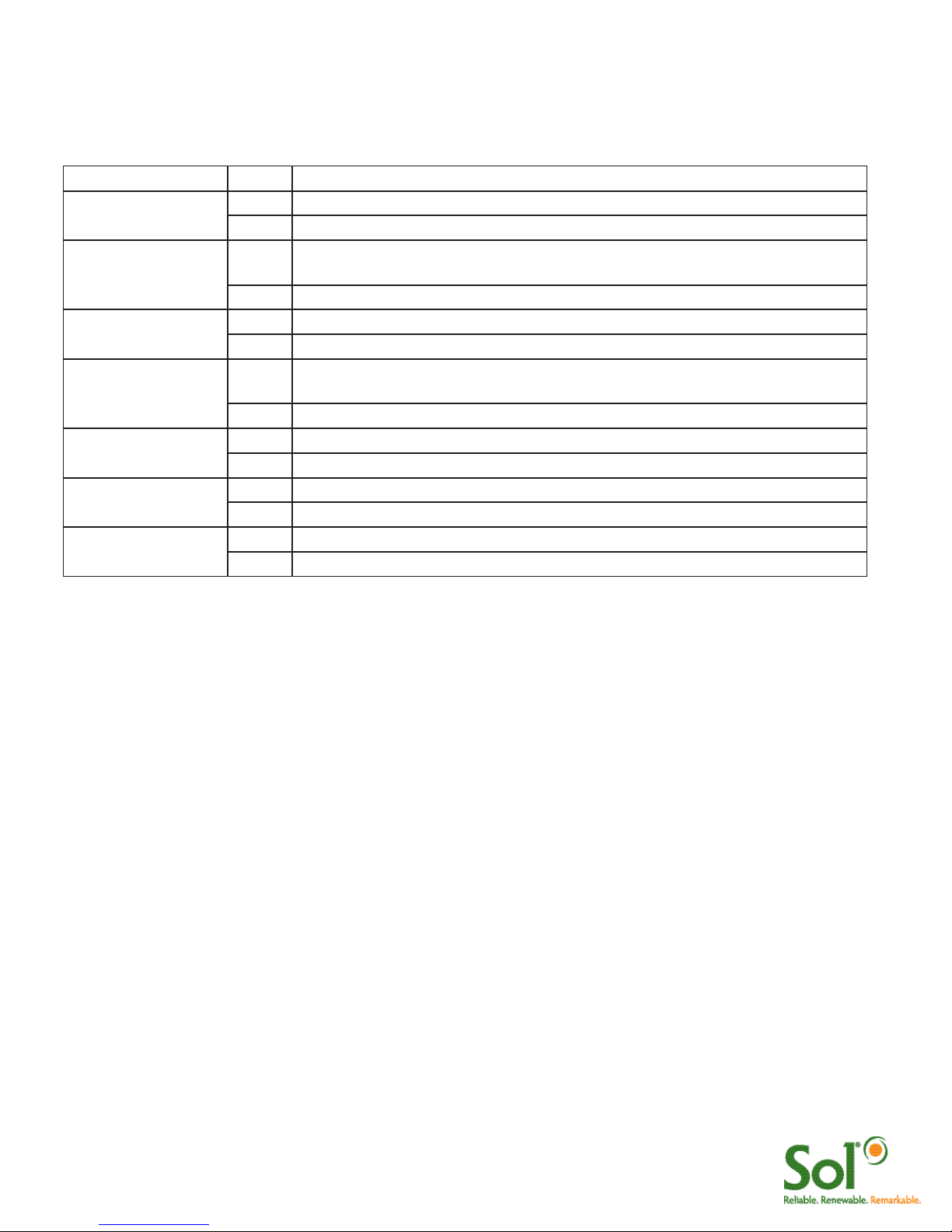
Programmed Run unit label reads:
06.100.000.00.000
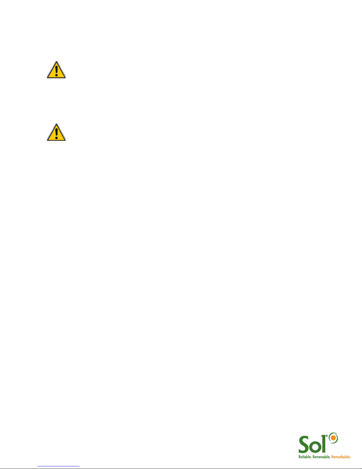
Split Night w/ Dimming (4 hours
at full, dim to 50%, 2 hours at full)
unit label reads:
04.100.050.02.100
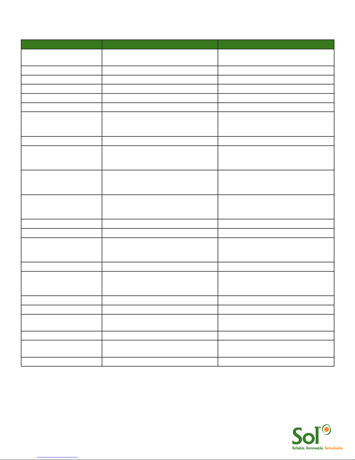
Split Night (4 hours at full, turn off,
2 hours at full) code:
04.100.000.02.100

10 GreenWay™ installation & operation manual 0410 MKTG-IM-GREEN-002
Solar Light System Test
Once all of the wires have been clicked together and the batteries are installed, perform a diagnostic test.
Press the “PUSH TO TEST” Button. This will indicate to the CPU to turn on the LED Luminaire(s) and
operate the lights at full intensity for 5 minutes. Several diagnostic LEDs will turn on & remain on for several
seconds. This is normal.
FIGURE 15 aiSUN™ SYSTEM TEST
Troubleshooting and Diagnostic LEDs
If the LED Luminaire turns on to full brightness, system operates OK and will automatically turn on & off with
sunset and sunrise.
If the LED Luminaire does not turn on as described, follow the Diagnostic LED table (below) to troubleshoot
the system.
If LED Luminaire does not turn on AND no Diagnostic LEDs are on, aiSUN™ is not powered, check battery
and fuse connections.
FIGURE 16 aiSUN™ TROUBLESHOOTING
11 GreenWay™ installation & operation manual 0410 MKTG-IM-GREEN-002
Q: Does aiSUN™ have a timeclock inside?
A: No, aiSUN™ does not have a “timeclock”, instead it uses the regular sun rise and sun set it detects to
determine when night is occurring and for how long. By averaging 10 nights of sunrise and sunset data the
CPU accurately determines length of night and when sunrise and sunset occur.
Q: What happens during daylight savings time?
A: Since aiSUN™ performs all of its timing based on sunrise and sunset daylight savings time has no impact
on the CPU. Daylight savings time is a clock change to accommodate having daylight hours align with
certain times of the day, despite what the clock says, when the sun set aiSUN™ turns on the solar light.
Q: Can I reprogram aiSUN™ to work a different way?
A: While it is possible to have aiSUN™ reprogrammed, it is important to consult with SOL Inc about what
operating modes are available. Solar lights can sometimes run longer or brighter, however this typically
requires a larger solar panel and more battery reserve to provide more light, longer. These types of changes
are costly but are possible, contact SOL Inc.
Q: What does aiSUN™ stand for?
A: ai stands for adaptive intelligence, SUN indicates that aiSUN™ is for solar charging.
Frequently asked Questions about aiSUN ™
Diagnostic LEDs
aiSUN™ has diagnostic LEDs to indicate of the status of the Solar Light it is controlling. See the table
(Figure 17) below to understand the function of the LEDs.
Indicator Name Status Meaning
LED
(Luminaire Status)
ON Luminaire ON
OFF Luminaire OFF
DIM ON LED fixture is in Power Save mode - battery voltage is LOW. Contact SOL
Inc Customer Support
OFF Dimming due to Power Save is NOT active - battery voltage level is OK
Charge ON aiSUN™ is charging the battery
OFF aiSUN™ is not charging the battery
Low Volt Disconn FLASH Battery is disconnected or too low to operate the LED fixture. Contact SOL
Inc Customer Support
OFF Battery condition is OK
Code 2
(future use)
Code 1 ON If system is a dual LED fixtures system; one fixture is disconnected
OFF Fixtures are OK
Fault ON LED fixture issue: short circuit or open circuit
OFF Fixtures are OK
FIGURE 17 LED DIAGNOSTIC TABLE

12 GreenWay™ installation & operation manual 0410 MKTG-IM-GREEN-002
OPERATION, MAINTENANCE, TROUBLESHOOTING
Break-in Period
After the SOL GREENWAY® Light is installed; the battery, LED fixture, and controller require a break-in period
before reaching peak performance and efficiency:
1. New batteries achieve full charging capacity after they have been used for approximately 4-5 days.
Before that, they achieve approximately 85% of their rated charging capacity.
2. The LED fixture must operate for several days before it reaches its peak output. This will not be
noticeable.
3. The controller must operate for approximately one week before learning the system’s parameters and
achieving maximum efficiency.
4. The system may need a full day of peak sun to reset all of its circuits. If the system is installed during a
period of inclement weather or late in the day, the system may not operate the first night.
The break-in period will not affect normal performance of the light unless the break-in period occurs at a time
that the system is operating at its extreme limits. This may be the case if the system is installed during the
winter months or during a period of successive bad weather days.
Expected Performance
The SOL GREENWAY® Light is designed to provide reliable operation and illumination all year. The solar
panel provides enough energy during a normal day to charge the battery for operation of the LED fixture for
the following night. The system is designed with a five-day reserve charge. As a result, extended periods of
low sun may deplete the five-day reserve and affect performance of the system.
The following conditions may cause your SOL GREENWAY® Light to operate out of specification:
1. Prolonged Bad Weather. A series of days with low levels of sunlight may deplete the battery reserve.
Depending on the severity of the condition, the nightly illumination period could be reduced until a sunny
day re-establishes the reserve battery charge. Please note that the system may need anywhere from two
days (in summer) to ten days (in winter) of good sunny weather before the full five-day battery reserve is
completely achieved.
2. Shading. Installation of the SOL GREENWAY® Light in a location where the solar panel is shaded
during part of the day will inhibit the ability of the solar panel to fully charge the battery and may severely
damage the battery. The hours of nighttime illumination will be reduced by the controller if the solar panel
cannot fully charge the battery.
If you believe that your SOL GREENWAY® Light is not performing as expected and the above conditions do
not apply, please contact SOL technical support at 1.800.959.1329 option #3.

13 GreenWay™ installation & operation manual 0410 MKTG-IM-GREEN-002
Preventive Maintenance and Service
Tree Branch Clearing
Trim tree branches (and remove any other obstructions) in the vicinity of the solar panel(s) once every three
months.
Solar Panel Cleaning
The solar panel(s) should be cleaned periodically to insure optimum performance.
1. Using a non-streaking window cleaner and a soft cloth, thoroughly wipe down the solar panel(s) to
remove any dirt and grime that may have accumulated.
2. Dry the solar panel(s) with a soft clean cloth.
3. Repeat Steps 1 and 2, if necessary, until all dirt and grime have been removed.
Fuse Replacement
If the SOL GREENWAY® Light does not operate, check the fuse.
1. Open the battery box.
2. Remove the fuse cover on the fuse holder.
3. Remove the existing fuse, insert the new fuse, and replace the fuse cover.
4. Test the system.
5. Close the battery box.
LED Fixture Replacement
1. Remove the socket head bolts that secure the LED fixture to the arm (see Figure 14 for details).
2. Slide the LED fixture off the arm.
3. Disconnect the LED fixture from the load cable.
4. Insert the new LED fixture, following Steps 1 through 4 on page .
5. Open the battery box and press the white TEST button on the controller until a distinct click is heard and
felt. The LED fixture will illuminate for five minutes, and the red LED will begin to flash.
6. Close the battery box, and close the fixture cover.
Note: A plastic scraper may also be needed for removing bird droppings.
Note: Solar panels can get very hot when the sun is out. It is advisable to clean solar panels during
the early morning hours.
Note: If the fuse needs to be replaced, be sure to also check operation of the controller.
Note: The LED in the fixture is not serviceable. The entire LED fixture assembly must be replaced.
14 GreenWay™ installation & operation manual 0410 MKTG-IM-GREEN-002
Battery Replacement
1. Remove the battery box cover.
2. At the controller, disconnect the solar array harness connector, then disconnect the single aiSUN™
harness from the battery harness.
3. Remove the battery from the battery box.
4. Disconnect the battery harness from the old battery and attach to the new battery.
5. Place the new battery in the battery box.
6. At the controller, connect the aiSUN™ single harness to the battery harness, then connect the solar array
harness.
7. Replace the battery box cover.
Caution: When disconnecting the cables, be sure to disconnect the solar array harness first.
Caution: When reconnecting the cables, be sure to connect the aiSUN™ single harness from
the battery first. Then connect the pv array harness.
15 GreenWay™ installation & operation manual 0410 MKTG-IM-GREEN-002
PROBLEM POSSIBLE CAUSE SOLUTION
The light does not turn on
at all.
The battery is discharged. Charge the battery.
The battery is bad. Replace the battery.
The LED fixture is bad. Replace the LED fixture.
The fuse is blown. Replace the fuse.
The controller is bad. Check the controller.
The light does not stay on
for the expected period of
time.
The run time is incorrectly set. Check and reset the run time.
The light turns on at dusk
but does not turn on again
at dawn (split run time).
The run time exceeds the maximum run
time for your model and location.
Contact SOL for assistance.
Low battery voltage caused by
inclement weather.
Allow for two to three days of
consecutive sunny weather to charge
the battery pack.
Low battery voltage caused by shading
of the solar panel.
Clear tree branches and other
obstructions from the vicinity of the solar
panel.
The battery is bad. Replace the battery.
The red LED on the
controller remains
illuminated.
Low battery voltage caused by
inclement weather.
Allow for two to three days of
consecutive sunny weather to charge
the battery pack.
The light does not operate
every day.
Low battery voltage caused by shading
of the solar panel.
Clear tree branches and other
obstructions from the vicinity of the solar
panel.
The battery is bad. Replace the battery.
The fuse blows repeatedly. There is a short circuit in the wiring. Check all system wiring for a short
circuit.
The battery voltage is less
than 9.0 volts.
The controller is bad. Check the controller.
The battery is bad. Replace the battery.
Troubleshooting

16 GreenWay™ installation & operation manual 0410 MKTG-IM-GREEN-002
SOL Inc Limited “Five Plus” Warranty Rev 8/09
SOL Inc. is an ISO 9000-2008 certified worldwide manufacturer that designs and manufacturers our own products
(vs. simply reselling or distributing other manufacturer’s products). Even though the best scenario involves never having
to actually use a company’s warranty, we are proud to offer what we believe is in fact the BEST WARRANTY available
in the industry, from a company that has been in business since 1990.
SOL Inc warrants the Owner (defined as the entity that has final title to the goods) of each new SOL lighting system
to be free from defects in materials and workmanship and to perform under normal use and service. SOL will, at
its option, repair or replace any system or system component that is defective in materials or manufacture within a
minimum of five (5) years after purchase. Additionally, specific items within SOL’s system have extended warranty
protection against failure as defined below:
Item Period
Solar PV Panel 20 Years
Mounting Hardware 20 Years
Pole (if provided) 20 Years
LED Light Engine (Lamp) 10 Years
LED Luminaire (Fixture) 10 Years
Wire Harnessing 10 Years
Electronics (Charge controller, LED driver) 10 Years
Energy Storage Array (Battery) 5 Years*
*Batteries provided by SOL Inc have a limited warranty providing for battery replacement (batteries must be provided
by SOL), from the date of shipment, with the following pro-rated coverage:
• 0 to 2 years: 100% credit (user pays 0% of the replacement battery price)
• 2 to 3 years: 60% credit (user pays 40% of the replacement battery price)
• 3 to 4 years: 40% credit (user pays 60% of the replacement battery price)
• 4 to 5 years: 20% credit (user pays 80% of the replacement battery price)
SOL Inc’s liability on any claim for damages arising out of or in connection with the manufacture, sale, installation,
delivery or use of the unit shall not exceed the purchase price of the system. The purchaser assumes and will hold
harmless SOL Inc in respect of all such loss.
For warranty service on SOL products please contact SOL Inc for a Return Material Authorization (RMA) number by
calling +1 (772) 286-9461. Any products or components that are returned to SOL without first obtaining a RMA may
not be issued any credit, and SOL shall not be responsible for said items.
This warranty does not cover damage or malfunction, as determined by SOL’s service technicians or engineers, due
to abuse, misuse, incorrect installation, or accident such as, but not limited to:
• Use of incorrect mounting hardware
• Failure to follow operating and installation instructions provided by SOL
• Failure to maintain & operate the equipment in accordance within all applicable standards & codes
• Failure to maintain & operate the system under SOL’s specified operating conditions
• Vandalism or theft
• Fire, flood, “Acts of God”, and other problems beyond the control of SOL
• Unauthorized or improper repairs or adjustments
• Labor costs to remove, service, troubleshoot, and install all or part of SOL systems, unless previously agreed to
and authorized IN WRITING by SOL Inc. by either the Customer Care Manager, Quality Manager, or CEO
• Equipment service, rental, and or tools required to remove, service, troubleshoot, and reinstall all or part of SOL
systems, unless previously agreed to and authorized IN WRITING by SOL by either the Customer Care Manager,
Quality Manager, or CEO
• Components and equipment external to the SOL system
• The cost of repairing or replacing property other than the SOL system
• Equipment not provided by SOL
The use of any replacement parts (for any reason) including but not limited to electrical components, luminaires, or
batteries NOT provided by SOL Inc voids this warranty. This warranty is in lieu of all other expressed warranties and the
implied warranty of merchantability is limited to terms of this written warranty. This warranty grants
you specific legal rights, and you may have other rights which vary based on your location.

SOL Inc. | 3210 SW 42nd Avenue | Palm City, Florida 34990
www.solarlighting.com
E-mail support: [email protected]
Phone: +1.772.286.9461 | Toll: 800.959.1329 (USA & Canada)
Fax: +1.772.286.9616
Office Hours: Monday - Friday: 8:30am to 5:00pm (EST)
© 2010 SOL Inc. All rights reserved
In-Warranty Service Instructions
A Returned Merchandise Authorization (RMA) number must be obtained from SOL Inc. before equipment
can be returned for repair or replacement under warranty.
We require the following information before we can issue an RMA number:
• Controller Number for the product being returned
• Serial Number of the product being returned
• A description of the problem
• The address to which the repaired or replaced product is to be shipped
Equipment being returned must be properly packaged to protect it from damage during shipment. Shipping
costs and insurance to SOL Inc. are the responsibility of customer.
Upon verification of failure due to defects in materials or workmanship, we will either repair or replace the
product at our discretion. The customer will be responsible for all shipping and handling charges for any
equipment that is sent to SOL Inc. in error (no definable problems).
Contact us for Help
If troubleshooting does not work and further help is required, please call our 24/7 telephone technical
support number: (772) 286-9461, option #3.
This manual suits for next models
2
Table of contents
Other Sol Inverter manuals

Popular Inverter manuals by other brands

Alpha Outback Energy
Alpha Outback Energy SPC Series user manual

Kaco
Kaco blueplanet XP10U-H4 PSD instruction manual

electroil
electroil ITTPD11W-RS-BC Operation and Maintenance Handbook

ATON
ATON RA.Store-3 user manual

MULTIQUIP
MULTIQUIP GDP-5H Operation and parts manual

Kohler
Kohler 14RESA installation manual


