Flexsolar C120 Instruction Manual

A B CE F GH L I
K
120W FOLDABLE SOLAR PANEL
INSTRUCTION MANUAL & WARRANTY
MODEL C120
PN: FLC-C4-201200-4
ACCESSORIES INCLUDED:
20A / (12V/24V)
PWM controller
Carry bag
10 in 1
interchangeable
connectors
1’ (0.3m) cable
with Anderson
to DC5521 male
connector
1’ (0.3m) cable
with Anderson
to alligator clip
cable
1’ (0.3m) cable
with bare cable
with Anderson
connector

2
Thank you for purchasing this FLEXSOLAR® product. Before operating, please read
these instructions carefully. This instruction manual contains information for safe
use and maintenance of the product.
Please keep this instruction manual in a safe place for future reference.
The manufacturer does not accept responsibility for any damages due to not
following these instructions.
TABLE OF CONTENTS
General
Safety Precautions for Using a Foldable Solar Panel
General Operation Notes
Pg. 02
Product Overview
120W Foldable Solar Panel
Cables
Solar Charger Controller (PWM)
Pg. 04
Before Using
What’s in the Box
Pg. 12
Operation
Installation
Choose the location
System Connection
Pg. 13
Maintenance Pg. 15
Warranty Statement Pg. 16
GENERAL
Please carefully read the following operation and safety instructions. Non-compliance
with these instructions may void the product warranty.
This guide contains information regarding the operation and safe handling
FLEXSOLAR® solar panels and components. All operations must be read and
understood before attempting operation. If there are any questions, please contact
your dealer or FLEXSOLAR® customer support for further information.
The user should conform to all safety precautions in the guide when using solar
panels. Before using a solar photovoltaic system (including cable, power station

3
or other electric equipment), the user should be familiar with the mechanical and
electrical requirements for photovoltaic systems. Keep this guide in a safe place for
future reference.
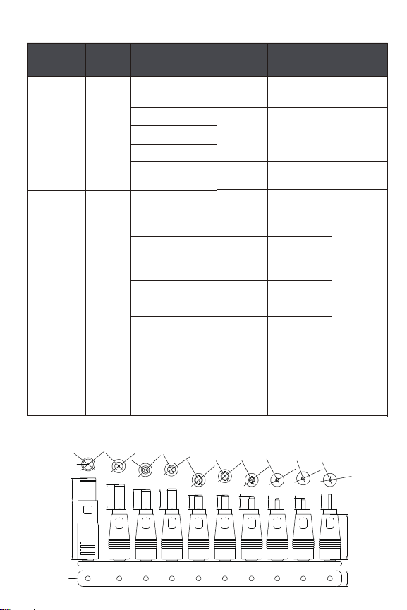
• All solar panels come with permanently attached output ports. Your dealer can
provide additional extension cables to simplify module wiring.
• Exercise caution when wiring or handling solar panels exposed to sunlight.
• Photovoltaic solar panels convert light energy to direct-current electrical
energy and are designed for outdoor use.
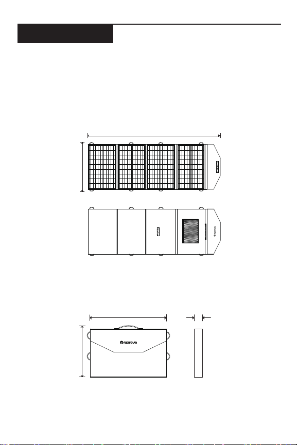
• Solar panels may be hung, placed flat, or use provided kickstand to face
towards the sun.
• Do not frequently connect or disconnect wires attached to solar panels when
they are exposed to sunlight in order to extend panel service life.
• Do not attempt to disassemble the solar panel, and do not remove any
attached nameplates or components. Doing so will void the warranty.
• Do not apply paint or adhesive to the solar panel.
• Do not use mirrors or other hardware to artificially concentrate sunlight on the
solar panel.
Safety Precautions for Using a Foldable Solar Panel
• Solar panels produce electrical energy when exposed to sunlight.
• FLEXSOLAR® solar panels can be connected in series. When connected together
(either in series or parallel), make sure that each solar panel has the same
rated voltage. Your dealer can provide additional cables to simplify panel
connections.
• Observe the instructions and safety precautions for all other components used
in the system, including wiring, cables, connectors, and etc.
• Use only equipment, connectors, wiring, and mounting hardware suitable for
use in a photovoltaic system.
• Always use the same type of solar panel in a particular photovoltaic system.
• Under normal operating conditions, solar panels will produce currents and
voltages that may vary from those listed in the data sheet. Data sheet values
are applicable at standard test conditions only.
General Operation Notes
• Do not stand or step on the solar panel.
• Do not drop the solar panel or allow objects to fall on the solar panel.
• Do not place any heavy objects on the solar panel.

4
PRODUCT OVERVIEW
120W Foldable Solar Panel (FLC-C4-201200-4)
FLEXSOLAR® solar panels are made of monocrystalline solar cells in series with high
efficiency, high transmission rate, and anti-aging EVA. They are designed for easy use,
extended longevity, and portable operation.
Unfolded View of the 120W Foldable Solar Panel:
Folded View of the 120W Foldable Solar Panel:
359mm/ 14.1inch
564mm/ 22.2inch 41mm/ 1.6inch
564mm/ 22.2inch
1653mm/ 65.1inch

5
Specifications
Maximum Power (Pmax) 120W
Max Power Voltage (Vmp) 19.8V
Max Power Current (Imp) 6.06A
Open Circuit Voltage (Voc) 23.7V
Short Circuit Current (Isc) 6.36A
Cell Efficiency 22%
Cell Type Monocrystalline
Power tolerance ± 10%
Temperature Co-efficient (Power) -0.45%/ °C
Temperature Co-efficient (Voltage) -0.32%/°C
Temperature Co-efficient (Current) +0.02%/ °C
NOCT (Air 20°C, Sun 0.8kW/m², Wind
1m/s)
45±2°C
Weight (Includes Accessory Items) 10.1 lbs/(4.6kg)
Operation Temperature
IP Rating IP65
Cables
• Passed conduction test, there was no short circuit, open circuit, dislocation, etc.
• Cables are free of dirt, scratches, damage, color difference or other defects.
• All materials meet RoHS environmental standards.
-4 F to 149 F (-20℃ to 65℃)

6
Specifications
Category Location Description Cable
Length
Wire
Specification
Remark
Output
Ports
From
junction
box
Suspension line of
USB 2.0
3 ft
(1 M)
16AWG Connected
Type C (PD 60W) / / Built In
LED Indicators
USB 3.0
Suspension line of
Anderson
Accessories /
1 ft
(0.3 M) 16AWG /
/ 16AWG
1 ft (0.3 M) 16AWG
10 ft
(3 M) 16AWG Connected
Note: the specification of 10-in-1 interchangeable connectors is below
Bare cable with
Anderson
connector
Anderson to
alligator
clip cable
10-in-1
interchangeable-
connectors
PWM Cotroller
Anderson to
DC5521
male connector
Polyester case
1 ft (0.3 M) 16AWG
/
/
20A/12V
With velcro
storage
pocket
/
/
A B CE F GH L I
13.80±0.5
12.0±0.5
12.4±0.5
11.0±0.5
10.8±0.5
10.4±0.5
11.4±0.5
K
14.0±0.5
9x26±0.5
33±0.5
11±0.5
5.5x2.1
female head
7.9x5.6x0.9mm
0.9mm
1.4mm
6.3x3.0mm 5.5x2.5mm
Φ5.6±0.1
Φ7.9±0.1
11.0±0.5
10.4±0.5
Φ4.3±0.1
Φ6.0±0.1
Φ3.0±0.1
Φ6.3±0.1
Φ5.5±0.1
Φ2.5±0.1
Φ5.5±0.1
Φ1.7±0.1
Φ1.7±0.1
Φ4.8±0.1
Φ1.7±0.1
Φ1.35±0.1
Φ4.0±0.1
Φ3.5±0.1
Φ1.1±0.1
Φ3.0±0.1
Φ0.7±0.1
Φ2.5±0.1

7
20A Pulse Width Modulation (PWM) Controller
• Built-in industrial micro controller.
• Big lcd display, all adjustable parameter
• Full 3-stage PWM charge management.
• Built-in short-circuit protection, open-circuit protection, reverse protection,
over-load protection.
• Dual MOSFET reverse current protection, low heat production.
Safety Instructions
1. Make sure your battery has enough voltage for the PWM to recognize the battery
type before first installation.
2. The battery cable should be as short as possible to minimize loss.
3. The PMW is suitable for lead acid batteries (Flood, AGM, GEL) and lithium ions,
(please make sure the PWM is set for the right type of battery before usage). It is not
suited for nickel metal hydride, or other types of batteries.
4. The PWM is only suitable for regulating solar modules. Never connect any other
charging source to the PWM.
5. It is normal for the PWM to be hot when the PWM is at work. Please install the PWM
on a flat and well-ventilated place.
SOLAR CHARGER CONTROLLER (PWM)

8
1Positive solar input terminal 5Positive load output terminal
2Negative solar input terminal 6Negative load output terminal
3Positive battery output terminal
4Negative battery output
terminal
20A Pulse Width Modulation (PWM) Controller
Cable for solar panel connection 20AWG
Cable for battery connection 20AWG
Connector N/A - customer to supply the
connection to battery based on
configuration
Dimension (W x H x D) 5.2*2.8*1.3 inch (133*70*34mm)
Net Weight 0.34lb/(154g)
Operation Temperature -31°F to 149°F (-35°C to 65°C)
Lithium
battery
Settable
voltage
Build-in
timer
MCU
control
SOLAR CHARGE CONTROLLER
USB
-
/
+
1 2 3 4 5 6

9
LCD Display/Key
Display Settings
Menu: switch between different display, or to enter/exit setting by long press.
Up: press to increase value
Down: press to decrease value
Attention:
1. Press the [down] button to on/off load manually at main display.
2. The work mode is working as below:
[24H] Load output 24 hours
[1-23H] Load on after sunset and closed after, setting hours
[0H] Dusk to dawn
+
MENU
UP
DOWN
/
ON/OFF
-/
V%
AH hour
amper
load
output
battery
solar panel
voltage
digital display
charge
on:equalation/buce
flicking:float
e
ect
V
H
V
V
V
main display
1
battery type
6
work mode
5
float or CV voltag
2
discharge reconn
3
discharge stop
4
Browsing
Interface
Press menu to
browse different
interface
Set
Parameter
In interface 2-5,
long press menu
to enter setting,
and using [up]
[down] to set the
parameter, long
p r e s s m e n u
ag a i n to e x i t .
long press
[down]

10
Charging Parameters
NOTE:
1). Charging parameters may vary based on availability of sunlight on the solar
panels.
2). Product specifications are subject to change without notice.
3). Bold italic typeface voltage *2, *4 while using 24/48 system.
MODEL 1210 1220 1230
SYSTEM VOLTAGE 12V/24V AUTO
Charge Current 10A 20A 30A
Discharge Current 10A 20A 30A
Max Solar Input <50V
Battery Type b01Sealed b02GEL b03Flood
Equalization 14.4V 14.2V 14.6V
Float Charge 13.7V (default, adjustable)
Discharge Stop 10.7V (default, adjustable)
Discharge Reconnect 12.6V (default, adjustable)
Battery Type b04 Iron
lithium 4
Strands
b05 Iron
lithium 5
Strands
b06 lithium
ion 3 Strands
b07 lithium
ion 4
Strands
Constant Charging
Voltage 3.6V*4/*5 4.2V*3/*4
Recovery Charge Voltage 3.4V*4/*5 4.0V*3/*4
Low Voltage Protection 2.6V*4/*5 3.1V*3/*4
Low Voltage Recovery 2.9V*4/*5 3.7V*3/*4
b04~b07 Parameters can’t be set
USB Output 5V/2A
Self-consume <10mA
Operating Temperature -35~+60°C
Size/Weight 133*70*34mm/154g

11
Troubleshooting
Situation Probable Solution
Charge icon not on
when sunny
Solar panel opened or
reversed
Reconnect
Load icon off
Mode setting wrong Set again
Battery low Recharge
Load icon slow flashing Over load Reduce load watt
Load icon fast flashing Short circuit protection Auto reconnect
Power off Battery too low/
Reverse
Check battery/Connection

12
BEFORE USING
What’s in the Box
Make sure you have all the following items included in the package. If any item is
damaged or missing, contact your dealer.
• 1 x 120W Solar Panel
• 1 x 1’ (0.3m) cable with anderson to DC5521 male connector
• 1 x 10-in-1 interchangeable connectors
• 1 x 1’ (0.3m) cable with Anderson to alligator clip
• 2 x 1’ (0.3m) bare cable with anderson connector from PWM
• 1 x Carry bag
• 1 x User Manual
• 1 x PWM controller: 20A / (12V/24V)

13
OPERATION
Installation
1. Remove the product from the box.
2. Unfold and support the fordable solar panel like the sketch map below:
• Lift and lay flat the portable solar panel;
• Unfold the four sides of the panel;
• Unfold the panels again to fully open the solar panel;
• Either lay the panel on a flat surface or hang the panel using the hooks.;
4. Adjust the face of the fordable panel toward the sunlight

14
Choose the location
• Choose a flat location to place the solar panel.
• Place the solar panel in an open location. Make sure the panel can be exposed
to the sun directly and avoid any shadow on the surface.
• Make sure the angle between panel and the sunlight is close to 90 degrees.
System Connection
There are two popular connections with solar system, including solar panel, power
station, electronic equipment, and so on. For the power station as energy storage, the
system connection as below
1. Charge Power Station
• Connect the fordable solar panel to power station directly
• Connect the power station to the electronic equipment, like phone, iPad, laptop
and so on.
Note: The electronic equipment can also be charged directly using USB outputs from
the PWM controller while there is no power station.
2. Charge battery through the PWM (Solar Charge Controller)
• Connect the cable from the battery to the PWM battery output terminals first.
• Wait until the PWM recognizes the battery type.
• Connect the cable from solar panel to the PWM solar input terminal.
NOTE: IT IS VERY IMPORTANT TO FOLLOW THE ABOVE-MENTIONED CONNECTION STEPS
TO AVOID DAMAGING THE PWM CONTROLLER (SOLAR CHARGE CONTROLLER). ALWAYS
CONNECT THE BATTERY TO THE PWM BATTERY TERMINALS BEFORE CONNECTING THE
PWM TO THE SOLAR PANEL.
LED Indicator
• Red Light – panel exposed to sun light
• Green Light - after connect electronic equipment to the type C output port
USB-C
(PD 60W)
Anderson LED
USB A
USB w/
QC 3.0

15
MAINTENANCE
• Clean the surface of the solar panel when needed. Always use a soft sponge
or cloth for cleaning. A mild, non-abrasive cleaning detergent may be used to
remove stubborn dirt. Don’t clean when the panel surface is hot.
• Clean solar panels more frequently during drier months, as they may become
covered in dust more quickly. A pressure washer is not recommended.
• Caution: Observe the maintenance instructions for all components used in the
system, such as support frames, charge controller, batteries, etc.
+-
+
-
+
-
Lit hium
battery
Set tab le
voltage
Bui ld- in
tim er
MCU
con tro l
SOLAR CHARGE CONTROLLER
USB
-
/
+

16
WARRANTY STATEMENT
FLEXSOLAR® warrants to the original consumer purchaser that the FLEXSOLAR®
product will be free from defects in workmanship and material under normal
consumer use during the applicable warranty period identified in the ‘Warranty
Period’ section below, subject to the exclusions set forth below. This warranty
statement sets forth FLEXSOLAR® total and exclusive warranty obligation. We will not
assume, nor authorize any person to assume for us, any other liability in connection
with the sale of our products.
Warranty Period:
The warranty period is 24 months. In each case, the warranty period is measured
starting on the date of purchase by the original consumer purchaser. The sales
receipt from the first consumer purchase, or other reasonable documentary proof, is
required in order to establish the start date of the warranty period.
Remedy:
FLEXSOLAR® will repair or replace (at FLEXSOLAR® option) any FLEXSOLAR® product
that fails to operate during the applicable warranty period due to defect in
workmanship or material. If a valid claim is made during the applicable period,
FLEXSOLAR®, at its option, will either (1) replace the product, or (2) exchange the
product with a product that is of equal value. A replacement product assumes the
remaining warranty of the original product or 60 days from the date of replacement,
whichever is greater. Customer is responsible for the return shipping costs.
Limited to Original Consumer Buyer:
The warranty on FLEXSOLAR® products is limited to the original consumer purchaser.
Exclusions:
FLEXSOLAR® warranty does not apply to (I) any product that is misused, abused,
modified, damaged by accident, or used for anything other than normal consumer
use as authorized in FLEXSOLAR® current product literature, or (II) any product
purchased through an online auction house.

17
How to Receive Service:
To obtain warranty service, you must contact our customer service team. If our
customer service team determines that further assistance is required, they will
give you a Return Material Authorization (“RMA”) number and will provide you with
return instructions. You must properly package the product, clearly marking the RMA
number on the package and including proof of your purchase date with the product.
We will process your return and send your repaired or replacement product to you in
continental North America.
Exclusive Remedy; Limitation of Liability:
The foregoing provisions state FLEXSOLAR® entire liability, and your exclusive remedy,
for any breach of warranty, express or implied.
IN NO EVENT WILL FLEXSOLAR® BE LIABLE FOR ANY CONSEQUENTIAL OR INCIDENTAL
DAMAGES ARISING FROM ANY USE OR MALFUNCTION OF ANY FLEXSOLAR PRODUCT, OR
FROM ANY BREACH OF WARRANTY, INCLUDING DAMAGE TO OTHER DEVICES. IN NO EVENT
WILL FLEXSOLAR’S LIABILITY FOR ANY CLAIM, WHETHER IN CONTRACT, WARRANTY, TORT
(INCLUDING NEGLIGENCE AND STRICT LIABILITY) OR UNDER ANY OTHER THEORY OF LIABILITY,
EXCEED THE AMOUNT PAID BY YOU FOR THE FLEXSOLAR® PRODUCT.
Some states or provinces do not allow the exclusion or limitation of incidental or
consequential damages, so the above limitation or exclusion may not apply to you.

INNOTECH ENTERPRISE LLC
Customer Support:
800-620-1249
flexsolarenergy.com
Innotech Enterprise LLC is a wholly subsidiary of Flextech Company.
FLEXSOLAR® is a registered trademark of Flextech Company.
®All rights reserved.
©2013-2024 FLEXSOLAR® is a trademark licensed for use by Flextech Company and
registered in the U.S.
FLC-C4-201200-4
Product Label: UPC code:
Serial Number:
Model Type
Max Peak Power (Pmax |W)
Maximum Power Point Voltage (Vmp |V)
Maximum Power Point Current (Imp |A)
Open Circuit Voltage (Voc |V)
Short Circuit Current (Isc |A)
Normal Operating Cell Temperature (NOCT)
Temperature Range (℃)
Power Tolerance
Application Class
Net Weight kg/(lbs)
Dimensions (unfolded) mm/in
Dimensions (folded) mm/in
All technical data at Standard Test Condition (STC)
Standard Test Condition (E=1000W/m2, Tc=25℃, AM 1.5)
FLC-C4--201200-4
120W
19.8V
6.06A
23.7V
6.36A
45±2℃
-20℃~+65℃
±10%
Class A
4.2kg/(9.3lbs)
1653x564x5 mm/65.1x22.2x0.2 in
564x359x41 mm/22.2x14.1x1.6 in
Gross Weight kg/(lbs) 4.9kg/(10.8lbs)
WARNING ELECTRICAL HAZARD
Only qualified personnel should install or perform
maintenace work on these modules.
This unit produces electricity if exposed to light.
Follow all applicable electrical safety precautions.
Don’t disconnect when loading.
Don’t damage or scratch the suface of the module.
785249 51916 1
This manual suits for next models
1
Table of contents