ATON RA.Store-3 User manual

ATON S.r.l. Sede Legale: Via Nuova Circonvallazione, 57/B 47923 Rimini (RN)
Sede Operativa: Via Guido Rossa, 5 41057 Spilamberto (MO) Tel: +39 059/783939 Fax: +39 059/784323
E-mail: info@atonstorage.com Sito web: www.atonstorage.com
INDEX
1. INTRODUCTION ....................................................................................................................................................................... 3
2. DESCRIPTION OF THE SYSTEM................................................................................................................................................. 3
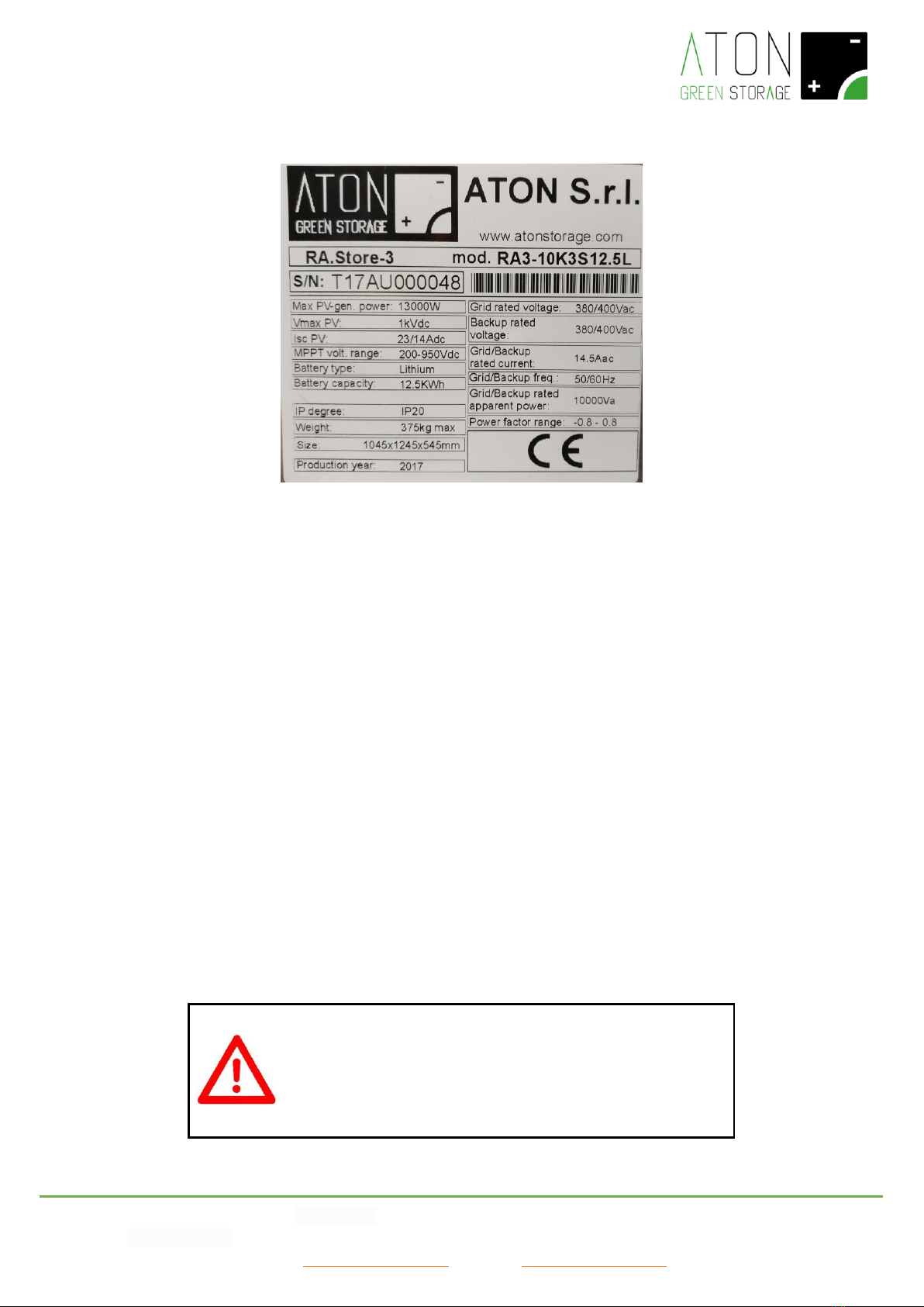
2.1 IDENTIFICATION PLATE............................................................................................................................................................... 8
2.2 SAFETY AND MAINTENANCE........................................................................................................................................................ 8
2.2.1 Maintenance on the AC lines of the building .............................................................................................................. 9
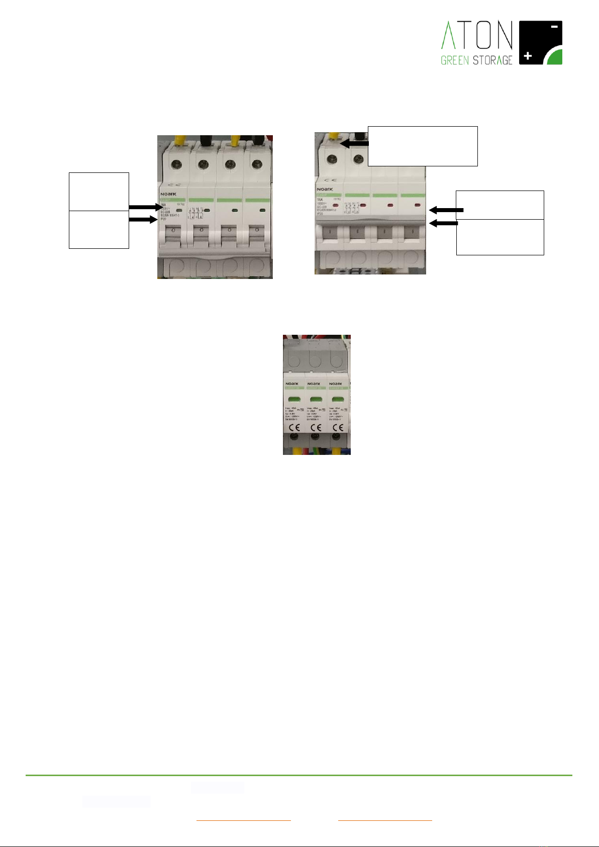
2.3 DESCRIPTION OF THE SAFETY SYSTEMS AND DEVICES........................................................................................................................ 9
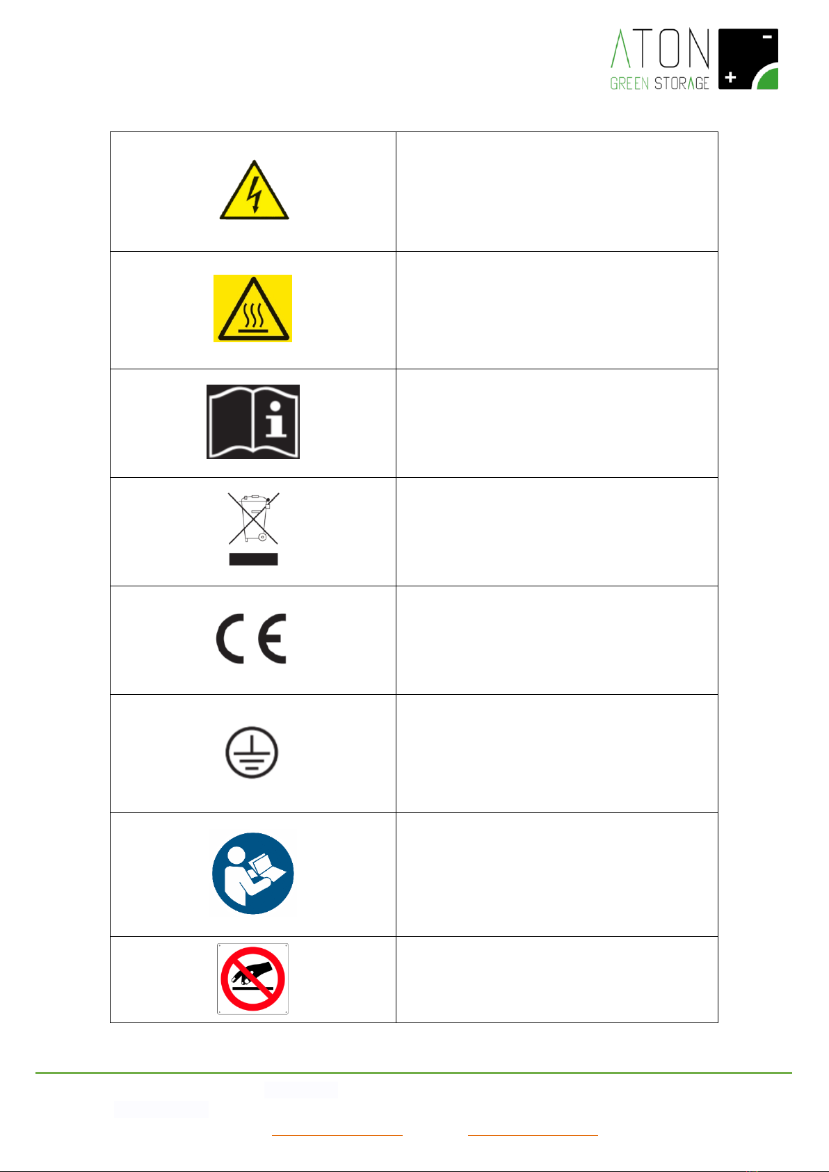
2.4 PICTOGRAMS AND WARNINGS ON THE SYSTEM............................................................................................................................. 10
3. FUNCTIONING........................................................................................................................................................................ 11
3.1 ON-GRID MODE .................................................................................................................................................................. 11
3.2 EPS MODE........................................................................................................................................................................... 11
3.3 MONTHLY RECHARGE OF THE BATTERY ....................................................................................................................................... 11
3.4 WINTER FUNCTIONING OF THE BATTERY (WINTER MODE) .............................................................................................................. 11
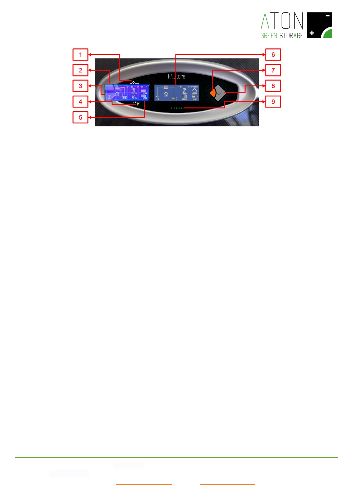
4. SCREENS OF THE DISPLAY...................................................................................................................................................... 12
4.1 MAIN SCREEN........................................................................................................................................................................ 13
4.2 STATISTICAL DATA SCREEN........................................................................................................................................................ 14
4.3 NUMERICAL DATA SCREEN ....................................................................................................................................................... 14
4.4 CONFIGURATION SCREEN......................................................................................................................................................... 16
5. CONNECTIVITY OF THE SYSTEM............................................................................................................................................. 18
5.1 MODIFICATION OF THE WIFI CONNECTIVITY ................................................................................................................................ 18
6. STATUSES OF THE SYSTEM..................................................................................................................................................... 25
7. PROBLEMS OF THE SYSTEM................................................................................................................................................... 26
8. SWITCH OFF AND ON THE SYSTEM........................................................................................................................................ 29
8.1 PROLONGED STOP .................................................................................................................................................................. 30
8.3 RA.STORE-3BPLUS ................................................................................................................................................................ 30
9. REMOVAL AND DISPOSAL OF THE SYSTEM............................................................................................................................ 31

ATON S.r.l. Sede Legale: Via Nuova Circonvallazione, 57/B 47923 Rimini (RN)
Sede Operativa: Via Guido Rossa, 5 41057 Spilamberto (MO) Tel: +39 059/783939 Fax: +39 059/784323
E-mail: info@atonstorage.com Sito web: www.atonstorage.com
1. Introduction
The present manual is addressed to the end customer and describes the main functions of the system RA.Store-3.
READ THE PRESENT MANUAL BEFORE STARTING ANY OPERATION
Before starting any operation, it is compulsory to read the present
User Manual.
The guarantee of good functioning and the full compliance of the
performances of the storage system are strongly connected to the
correct commitment of all instructions that are contained in this
Manual.
2. Description of the system
Picture 1 - RA.Store-3 system
In Picture 1, the following parts of the RA.Store-3 system are showed:
-Interface board (1): it allows the communication between the user and the system.
-Antenna (2): A GPRS communication module (or WiFi, as an optional) allows to send the data about the functioning of the
system to a portal accessible from internet, and the assistance service to execute any control in remote assistance.
-Electrical panel (3): it allows to switch on and off the system.
-CT sensor (not visible on the picture): there is an electricity sensor in order to control the energy exchanged with the public
grid.

ATON S.r.l. Sede Legale: Via Nuova Circonvallazione, 57/B 47923 Rimini (RN)
Sede Operativa: Via Guido Rossa, 5 41057 Spilamberto (MO) Tel: +39 059/783939 Fax: +39 059/784323
E-mail: info@atonstorage.com Sito web: www.atonstorage.com
Picture 2 –Interface board
The interface board shows the following parts (Picture 2):
-Graphic display with capacitive keyboard (6): it shows information regarding to the functioning of the system and it allows to
interact with it,
-Key Enter (8) and key Esc (7): together with the display they allow to interact with the system.
-Status led lights of the system:
-Active system (3): switched on if the system is active and switched off if the system is not active.
-Solar (1): switched on if the PV panels are supplying energy to the system, switched off in the opposite case.
-Grid (4): switched on if the public electric grid functions correctly, switched off in case of blackout, and flashing in case
of blackout and run down battery.
-WiFi Communication (5): switched on if the system is communicating the data regarding its functioning through the
WiFi card (optional), flashing if the system cannot communicate its data, and switched off if the WiFi communication is
not activated.
-Fault (2): switched on or flashing if there is an active alarm, switched off in the opposite case.
-Status led lights of the battery (9): the led lights represent visually the amount of energy in the battery. Moreover the
discharge and recharge phases are indicated with particular sequences of switching on of the led lights.

ATON S.r.l. Sede Legale: Via Nuova Circonvallazione, 57/B 47923 Rimini (RN)
Sede Operativa: Via Guido Rossa, 5 41057 Spilamberto (MO) Tel: +39 059/783939 Fax: +39 059/784323
E-mail: info@atonstorage.com Sito web: www.atonstorage.com
Picture 3 –Front side of the electrical panel
The electrical panel, as shown in Picture 3, is composed of two types of equipments:
- Automatic magneto-thermal breakers (Picture 4 and Picture 5): they isolate and protect the electrical lines on which they are
installed.
- Lightning arrestor SPD (Picture 6): it protects the system from overvoltages due to atmospheric origin.
1 2 3
4 5 6 7 8 9
INDICATOR OF
POSITION
1: ON (RED)
0: OFF (GREEN)

ATON S.r.l. Sede Legale: Via Nuova Circonvallazione, 57/B 47923 Rimini (RN)
Sede Operativa: Via Guido Rossa, 5 41057 Spilamberto (MO) Tel: +39 059/783939 Fax: +39 059/784323
E-mail: info@atonstorage.com Sito web: www.atonstorage.com
Picture 6 –Lightning arrestor SPD
On the electrical panel the user can access the following parts:
-Magneto-thermal breaker BATTERY (1): it protects the electrical line of the batteries.
In position of “1 - ON”:
-It activates and switches on the control and management card of the storage system;
-It activates the function of charge and discharge of the batteries.
In position of “0 - OFF”:
-It deactivates and switches off control and management card of the storage system;
-It deactivates the function of charge and discharge of the batteries.
-Magneto-thermal breaker GRID LINE (2): it connects the storage system to the house and the public electrical grid. This
outlet is supplied during normal conditions, i.e. when the national grid is at 400 Vac.
In position of “1 - ON”:
-It allows the supply of energy from the storage system to the house and the public electrical grid;
In position of “0 - OFF”:
Indicator of position
1: ON
Indicator of
position
0: OFF
Indicator of
status
0: GREEN
Indicator of status
1: RED
Indicator SPD
GREEN: OK
RED: TO BE REPLACED
Picture 4 - Automatic magneto-
thermal breaker in position of OFF –
Switched off
Picture 5 - Automatic magneto-
thermal breaker in position of ON
–Switched on

ATON S.r.l. Sede Legale: Via Nuova Circonvallazione, 57/B 47923 Rimini (RN)
Sede Operativa: Via Guido Rossa, 5 41057 Spilamberto (MO) Tel: +39 059/783939 Fax: +39 059/784323
E-mail: info@atonstorage.com Sito web: www.atonstorage.com
-It prevents the supply of energy from the storage system to the house and the public electrical grid.
-Magneto-thermal breaker EPS LINE (3): it connects the storage system to the house when there is a blackout, i.e when the
national grid is temporarily at 0 Vac.
-In position of “1 - ON”:
-It allows the supply of energy from the storage system to the house or only a part of it;
In position of “0 - OFF”:
-It prevents the supply of energy from the storage system to the house or only a part of it.
-Disconnnector panels string 1 “PV1 FIELD”(4): it connects the storage system to the first PV panels string.
-In position of “1 - ON”:
-It allows the supply of energy from the PV string connected to the entry of the storage system n.1 towards this latter;
-In position of “0 - OFF”:
It does not allow the supply of energy from the PV string connected to the entry of the storage system n.1 towards this
latter;
-Lightning arrestor “SPD PV1”(5): it protects the system from overvoltages due to atmospheric origin coming from the string
1.
-Disconnnector panels string 2 “PV2 FIELD” (6): it connects the storage system to the second PV panels string.
-In position of “1 - ON”:
-It allows the supply of energy from the PV string connected to the entry of the storage system n.2 to this latter;
-In position of “0 - OFF”:
It does not allow the supply of energy from the PV string connected to the entry of the storage system n.2 to this latter;
-Lightning arrestor “SPD PV2” (7): it protects the system from overvoltages due to atmospheric origin coming from the string
2.
-Disconnnector panels string 3 “PV3 FIELD” (8): it connects the storage system to the third PV panels string.
-In position of “1 - ON”:
-It allows the supply of energy from the PV string connected to the entry of the storage system n.3 to this latter;
-In position of “0 - OFF”:
It does not allow the supply of energy from the PV string connected to the entry of the storage system n.3 to this latter;
-Lightning arrestor “SPD PV3” (9): it protects the system from overvoltages due to atmospheric origin coming from the string
3.

ATON S.r.l. Sede Legale: Via Nuova Circonvallazione, 57/B 47923 Rimini (RN)
Sede Operativa: Via Guido Rossa, 5 41057 Spilamberto (MO) Tel: +39 059/783939 Fax: +39 059/784323
E-mail: info@atonstorage.com Sito web: www.atonstorage.com
2.1 Identification plate
Picture 7 - Identification plate
The CE identification plate shows the following data (Picture 7):
•Identification of the producer;
•Type of product and model;
•S/N: Serial Number of the product;
•Max PV-gen. power: the maximum power that can be produced by the PV panels towards the inverter;
•Isc PV: the maximum current value of short circuit for each entry on the DC side;
•MPPT volt. range: voltage range of MPPT;
•Battery type: the type of batteries installed in the storage system;
•Battery capacity: the nominal storage capacity of the batteries;
•IP degree: IP protection degree;
•Weight: the total weight of the storage system;
•Size: the dimensions of the storage system;
•Production year: the year in which the storage system is manufactured;
•Grid/Backup rated voltage: the voltage value available on the outlets “Grid” and “Backup”;
•Grid/Backup rated current: the maximum value of current produced by the inverter on the outlets Grid and Backup;
•Grid/Backup rated apparent power: the maximum value of apparent power produced by the inverter on the outlets
Grid and Backup;
•Grid/Backup freq.: the frequency range of the voltage coming from the inverter (it can be set up);
•Power factor range: the power factor range within the inverter is set up.
2.2 Safety and maintenance
GENERAL WARNINGS
Despite the design in full compliance with the essential safety
requirements and the installation of the proper safety devices, for a
correct use of the storage system please take into consideration all
the rules about accidents prevention listed in the present manual

ATON S.r.l. Sede Legale: Via Nuova Circonvallazione, 57/B 47923 Rimini (RN)
Sede Operativa: Via Guido Rossa, 5 41057 Spilamberto (MO) Tel: +39 059/783939 Fax: +39 059/784323
E-mail: info@atonstorage.com Sito web: www.atonstorage.com
-The end user is not allowed to execute any reparation, replacement or other intervention on the system, for his own safety,
the protection of the household appliances and the storage system itself.
-It is strictly forbidden to try to access the inner parts of the system and each intervention not executed by authorized staff
will invalidate the guarantee and the liability of the producer.
-Do not move the system because this may cause disconnections and false contacts.
-Do not alter in any way the system, including plates and instructions.
-The connection of the system to the grid and the PV panels is of permanent type and cannot be altered, except by authorized
staff.
-Do not put powders or liquids on the inner parts of the system.
-Keep the system away from flames or heat sources.
-Do not store inflammable materials nearby the system.
-In order to clean the system, use a normal duster and do not use inflammable or toxic solvents.
-Always ensure proper ventilation, avoiding to block the air intakes of the system.
The system does not require any maintenance provided by the end user apart from always ensuring proper ventilation, avoiding
to block the air intakes of the system, and the execution of the following visual checks:
- Parts that are mechanically damaged;
- Damaged electrical cables connected to the system.
In these cases, do not intervene on the system but please contact your authorized dealer.
2.2.1 Maintenance on the AC lines of the building
ATTENTION
Before executing any operation of maintenance on the AC lines of
the building, lower the disconnectors GRID and EPS (Picture 3).
2.3 Description of the safety systems and devices
The safety systems and devices installed on the storage system are the following:
-Protection casing of the battery space, battery charger and inverter;
-Protection against direct and indirect electrical contacts;
-Magneto-thermal breakers;
-Fuses.
In order that the protection system is efficient against the indirect contacts, it is necessary that the protection equipment
(earthing) of the general electrical installation of the building is duly dimensioned and efficient.
NOTE: The customer is liable for guaranteeing the efficiency according to the existing rules relating to the earthing of the
general electrical installation of the building.

ATON S.r.l. Sede Legale: Via Nuova Circonvallazione, 57/B 47923 Rimini (RN)
Sede Operativa: Via Guido Rossa, 5 41057 Spilamberto (MO) Tel: +39 059/783939 Fax: +39 059/784323
E-mail: info@atonstorage.com Sito web: www.atonstorage.com
2.4 Pictograms and warnings on the system
Electrocution hazard –presence of electricity. It is
therefore forbidden to try to enter the inner parts of
the system. All the works executed on the system
must be done by qualified technical staff.
Placed nearby the electrical panel.
Risk of burns due to hot surfaces.
Some areas of the product may get hot during the
functioning. Avoid the direct contact with the body
during the functioning. Before executing any activity
on the product, switch it off and leave it cool enough.
Respect all the indications given in the manuals and in
the technical datasheets.
RAEE / WEEE Waste
Do not dispose the product together with household
waste, but respecting all the local and European laws
regarding the disposal of electronical waste applicable
in the country of installation.
CE Mark
The product is compliant with the requirements
applicable by the EU Directives.
Appliance Class I
The chassis of the system is connected to the
protection conductor of the product. The protection
conductor of the product must be connected to the
earthing protection conductor of the house.
Refer to the present manual –please always read this
manual (and the installation manual in case of
technical authorized staff) before starting each
operation on the system.
Placed nearby the electrical panel.
It is forbidden to block or cover the air intakes of the
system.
Placed nearby the electrical panel.

ATON S.r.l. Sede Legale: Via Nuova Circonvallazione, 57/B 47923 Rimini (RN)
Sede Operativa: Via Guido Rossa, 5 41057 Spilamberto (MO) Tel: +39 059/783939 Fax: +39 059/784323
E-mail: info@atonstorage.com Sito web: www.atonstorage.com
3. Functioning
Ra.Store-3 is a system for the storage of the energy produced from photovoltaic panels and the supply of the stored energy.
It is possible to distinguish two different functioning modes of the system: the on-Grid mode and the EPS mode. The on-Grid
mode is used by the system when the public electrical grid is functioning correctly, whereas in case of blackout the system
activates automatically the EPS mode in order to solve the problem occurred, and then at last come back to the on-Grid mode
when the problem is solved.
In order to use the functioning mode called EPS it is necessary to install an external commutation electrical panel between the
two AC electrical lines of the storage system.
3.1 ON-GRID Mode
During the on-Grid mode, the electrical energy produced from the PV panels, if not consumed immediately, will charge the
battery of the system and, if there will be an overproduction, it will be transferred to the public grid. On the contrary, in case the
electrical energy produced from the PV panels is not enough to satisfy the needs of the consumptions, the lacking part will be
supplied by the battery and, if even this will not be enough, from the public grid.
During the on-Grid mode, it is possible to take energy from the battery as long as the charge of this latter is more than 20% and
the power able to be taken from the battery gradually reduces when the battery approaches this percentage.
This threshold guarantees a long life of the battery and an energy reserve in case of blackout of the public grid (EPS mode).
3.2 EPS Mode
During the installation phase, it is possible to set the system so that in case of blackout of the public grid it supplies a part of the
consumptions (the so called privileged household appliances).
NOTE: The distinction between privileged and non-privileged consumptions is set by the installator (under supervision of the
final user) and can be modified only by qualified technical staff.
In case of blackout of the public grid, only the privileged consumptions are authorized to use the energy (energy produced from
the PV panels and/or supplied by the battery).
During this mode, called EPS mode, it is possible to take energy from the battery as long as the charge of this latter is more than
10% and the power able to be taken from the battery gradually reduces together with the battery status.
In this mode, it is moreover active the EPS electrical socket in the electric panel of the system (picture 2, indicator 7).
This mode is showed through the status 074 –EPS MODE.
3.3 Monthly recharge of the battery
In order to protect the battery life, on the first day of each month the system makes automatically a recharge of the battery
group up to 90%. During this activity, the system prefers to charge the battery, obviously from the panels, rather than supply
energy to the consumptions. The stored energy will not be wasted away, because it is completely available for the consumptions
at the end of this recharge phase.
NOTE: If, during the 15 days before the first day of each month, the battery has already done a recharge up to 90%, the above
mentioned recharge will not be executed.
This mode is showed through the status 065 –RIGEN.RICARICA
3.4 Winter functioning of the battery (Winter mode)
In order to protect the battery life, if the temperature of the battery goes down under 0°C degrees, it will be activated a
charge/discharge functioning as described below.
The winter functioning stops automatically when the room temperature is above 5°C.
This mode is showed through the status 041 –WINTER MODE.

ATON S.r.l. Sede Legale: Via Nuova Circonvallazione, 57/B 47923 Rimini (RN)
Sede Operativa: Via Guido Rossa, 5 41057 Spilamberto (MO) Tel: +39 059/783939 Fax: +39 059/784323
E-mail: info@atonstorage.com Sito web: www.atonstorage.com
ROOM
TEMPERATURE
[°C]
MAX. CHARGE
CURRENT OF
THE BATTERY
[A]
MAX.
DISCHARGE
CURRENT OF
THE BATTERY
[A]
MIN.
DISCHARGE
VOLTAGE OF
THE
BATTERY[V]
MAX.
CHARGE
VOLTAGE OF
THE
BATTERY [V]
-10≤roomT. ≤
0
4
13
47
52.5
roomT. < -10
0 –INACTIVE
BATTERY
0 - INACTIVE
BATTERY
INACTIVE
BATTERY
INACTIVE
BATTERY
4. Screens of the display
On the display are showed the functioning data of the system in real time and in statistical format. The main screen shows the
data of produced and consumed power in real time and, by pressing on the keys Esc and Enter (Picture 2, indicators 7 and 8), the
user can access the other screens.
NOTE: after 30 seconds from the last pressure of a key, the display goes back to the main screen.
The elements of the different screens are described as follows.

ATON S.r.l. Sede Legale: Via Nuova Circonvallazione, 57/B 47923 Rimini (RN)
Sede Operativa: Via Guido Rossa, 5 41057 Spilamberto (MO) Tel: +39 059/783939 Fax: +39 059/784323
E-mail: info@atonstorage.com Sito web: www.atonstorage.com
4.1 Main screen
Picture 8 –Main screen
The interface board shows the following parts (Picture 8):
-Flux line of the energy (1): it shows the progress of the electric energy between PV panels, electrical grid, the consumer
(house), the battery. The flux is shown by the indicating line.
-Communication with the storage system (2): the presence of the 2 arrows in alternating direction shows that the
communication has been done.
-Date and time (3): indication of date and time.
-Indication of instantaneous active power of electrical grid (4): it shows the active power given to or purchased from the
national electrical grid expressed in Watt. If the visualized power is positive, then it means that the system is giving energy to
the electrical grid. If the visualized power is negative, then it means that the system is taking energy from the electrical grid.
-Indication of instantaneous active power of PV panels (5): it shows the active power produced by the PV panels expressed in
Watt.
-Indication of instantaneous active power of battery (6): it shows the active power given or taken from the battery expressed
in Watt. If the visualized power is positive, then it means that the system is charging the battery. If the visualized power is
negative, then it means that the system is discharging the battery.
-Indication of instantaneous active power of the house (7): it shows the active power requested by the house expressed in
Watt. It is always expressed with a positive number.

ATON S.r.l. Sede Legale: Via Nuova Circonvallazione, 57/B 47923 Rimini (RN)
Sede Operativa: Via Guido Rossa, 5 41057 Spilamberto (MO) Tel: +39 059/783939 Fax: +39 059/784323
E-mail: info@atonstorage.com Sito web: www.atonstorage.com
4.2 Statistical data screen
By pressing the Enter key repeatedly, the user can access the following screens.
Picture 9 - Statistical data screen
Please refer to Picture 9: regarding what is showed, the showed statistical data indicate:
a. DAY for the data relating to the last three days,
b. MONTH for the data relating to the last three months,
c. YEAR for the data relating to the last three years.
1. It indicates the measure unity with which the data are expressed.
2. Energy supplied by the PV panels in the indicated period.
3. Energy supplied by the battery to the household appliances in the indicated period.
4. Energy purchased from the public electrical grid in the indicated period.
5. Energy sold to the public electrical grid in the indicated period.
6. Energy used by the household appliances in the indicated period.
4.3 Numerical data screen
By pressing the Enter key again, the user can access the following screen with the main functioning data in numeric format. The
user can see a table, as shown in the following picture (Picture 10).
Picture 10 - Numerical data screen
In the table the following data are showed:
1. Current, voltage and power supplied by the PV panels string 1.
2. Current, voltage and power supplied by the PV panels string 2 (if available).
3. Charge status, current, voltage and power exchanged with the battery (with minus, it means that the energy is taken from
the battery).
4. Current, voltage and power exchanged with the public electrical grid (with minus, it means that the energy is taken from the
public electrical grid).

ATON S.r.l. Sede Legale: Via Nuova Circonvallazione, 57/B 47923 Rimini (RN)
Sede Operativa: Via Guido Rossa, 5 41057 Spilamberto (MO) Tel: +39 059/783939 Fax: +39 059/784323
E-mail: info@atonstorage.com Sito web: www.atonstorage.com
5. Current, voltage and power supplied to the household appliances.

ATON S.r.l. Sede Legale: Via Nuova Circonvallazione, 57/B 47923 Rimini (RN)
Sede Operativa: Via Guido Rossa, 5 41057 Spilamberto (MO) Tel: +39 059/783939 Fax: +39 059/784323
E-mail: info@atonstorage.com Sito web: www.atonstorage.com
4.4 Configuration screen
By pressing the Enter key again, the user can access the configuration screen.
Picture 11 –Configuration screen
Through WiFi or GPRS, the system is able to communicate its own functioning data.
By pressing on the WiFi icon (1) (Picture 11), it is possible to see and set up the parameters regarding the WiFi connectivity of
the system (please refer to the paragraph “WiFi connectivity of the system” for further details).
By pressing on the Gprs icon (2) it is possible to switch on and off the Gprs communication.
Finally by pressing on the “i” icon (3) the user can access the following menu (Picture 12)
Picture 12 –User Menu
Use the keys “arrow up”, “arrow down” in the display and “Enter” to select an item. Press the “Esc” key to go back to the
previous menu.
By selecting the item “Info”, it is possible to see the serial numbers of the main components of the system and the Directive
(item “Safety”) that the system is compliant with in order to connect it to the public grid (CEI-021 in Italy, VDE0126 in Germany,
etc.).
Picture 13 - Menu Info
The item “FW Version” shows the firmwares of the system used during the certification phase.
•FW Manager v2.07.xx
•FW Inverter v2.02.xx

ATON S.r.l. Sede Legale: Via Nuova Circonvallazione, 57/B 47923 Rimini (RN)
Sede Operativa: Via Guido Rossa, 5 41057 Spilamberto (MO) Tel: +39 059/783939 Fax: +39 059/784323
E-mail: info@atonstorage.com Sito web: www.atonstorage.com
•FW Charger v2.03.xx
•FW Controller v1.00.xx.yy
Picture 14 - Menu FW Version
In order to execute the Self Test (Directive CEI-021), select the item “Self Test”, then “Start Test”.
Picture 15 –Screen for the Self Test
The test will start and the messages “<* WAIT TESTING…1*>”, “<* WAIT TESTING…2*>”, “<* WAIT TESTING…3*>”… are
showed.
In case the test will not be successful, the message “<*** TEST FAILED ***>”will be showed, whereas if the test ends correctly
the screen with the test results will be showed.

ATON S.r.l. Sede Legale: Via Nuova Circonvallazione, 57/B 47923 Rimini (RN)
Sede Operativa: Via Guido Rossa, 5 41057 Spilamberto (MO) Tel: +39 059/783939 Fax: +39 059/784323
E-mail: info@atonstorage.com Sito web: www.atonstorage.com
5. Connectivity of the system
The system is able to communicate the data relating to its functioning through GPRS, LAN or WiFi. This service allows the user of
the system to check his PV installation through the webpage www.atonstorage.com, and the remote assistance to check in real
time the presence of eventual problems.
In case the service is active, the producer reserves the chance to update the Firmware of the system in order to improve its
performance, and the relating updated User Manual can be downloaded at the page www.atonstorage.com.
The connectivity of the system and therefore the remote assistance service are subject to the presence of internet connectivity
and this will be checked during the installation phase.
NOTE: The user of the system must check and guarantee the continuity of the internet connectivity in order to have the chance
to exploit the service of remote assistance.
For further information about the remote assistance service, please contact your authorized dealer.
5.1 Modification of the WiFi connectivity
It is possible to see and set up the parameters regarding the WiFi communication, for ex. in case your router is replaced or your
password changed and the system must be reconnected to the internet. In case the WiFi device is off, the screen in Picture 12,
Picture 16 will appear (Press “Yes” to switch on the device), otherwise the screen in Picture 17 will appear.
Picture 16 –Switch on the WiFi device
Picture 17 –Configuration of the WiFi device
By pressing “Info” (1), all the information regarding the configuration of the WiFi device is showed.
By pressing on the symbol “Wrench” (2), the procedure of configuration of the WiFi device is started.
By pressing “Reset” (3), the device is reset to the original set up.
By pressing “Off” (4), the WiFi device is switched off.
By pressing “Esc” (5), the system goes back to the configuration screen (Picture 17).

ATON S.r.l. Sede Legale: Via Nuova Circonvallazione, 57/B 47923 Rimini (RN)
Sede Operativa: Via Guido Rossa, 5 41057 Spilamberto (MO) Tel: +39 059/783939 Fax: +39 059/784323
E-mail: info@atonstorage.com Sito web: www.atonstorage.com
The procedure to be followed in order to connect the system RA.Store-3 to an existing WiFi line foresees the use of any device
equipped with WiFi connectivity (indicated as PC hereunder) and Web Browser:
1. Press on the symbol “Wrench” in Picture 17, then wait that on the display the message “Ra_Config WiFi network
enabled”appears.
2. Connect the PC to the WiFi network Ra_Config (Picture 18).
Picture 18
3. Launch the Web Browser of the PC
4. Digit 192.168.1.1 in the address bar. The page showed in Picture 19 will appear.
Other manuals for RA.Store-3
1
Table of contents
Popular Inverter manuals by other brands

Selectronic
Selectronic SP PRO Series instruction manual

NORTHERN ELECTRIC
NORTHERN ELECTRIC BDM-300 WiFi Installation & user manual

Vynckier
Vynckier Soltection RJ-1 installation manual

Schumacher
Schumacher PID-200-USB owner's manual

Cobra
Cobra CPI 850 operating instructions

Toshiba
Toshiba TOSVERT VF-AS1 Series instruction manual