Solair J AB Series User manual

Page 1 of 39
11EER Wall Mount
Air Conditioner
Models:
INSTALLATION INSTRUCTIONS
J18AB-A
J24AB-A
J24AB-B
J24AB-C
J30AB-A
J30AB-B
J30AB-C
J36AB-A
J36AB-B
J36AB-C
Manual: 2100-707D
Supersedes: 2100-707C
Date: 2-3-21
J18LB-A
J24LB-A
J24LB-B
J30LB-A
J30LB-B
J30LB-C
J36LB-A
J36LB-B
J36LB-C

Manual 2100-707D
Page 2 of 39
CONTENTS
Getting Other Information and Publications .... 3
Wall Mount General Information ......................... 4
Air Conditioner Wall Mount Model Nomenclature..... 4
Shipping Damage ................................................. 4
General ............................................................... 4
Duct Work ........................................................... 5
Filters ................................................................. 5
Fresh Air Intake ................................................... 5
Installation ............................................................... 6
Basic Installation Design and Application Planning.. 6
Wall Construction ............................................. 6
Outdoor Area Inspection.................................... 6
Condensate Water Drainage ............................... 6
Indoor Ducted and Non-Ducted Applications........... 6
Indoor Supply Airow........................................ 6
Indoor Return Airow........................................ 6
Ducted Applications ......................................... 7
Free Blow Applications...................................... 7
Thermostat or Indoor Temperature Sensor
Placement ....................................................... 7
Unit Installation ................................................... 7
Materials/Tool List ............................................ 7
Wall Preparation............................................... 8
Wall Mount Installation to Wall Surface .............. 8
Wiring – Main Power........................................... 16
Wiring – Low Voltage........................................... 16
Low Voltage Connections ................................. 16
Unit Shutdown Feature ................................... 16
Balanced ClimateTM Feature............................. 16
Ventilation Features ........................................ 17
Low Ambient Control (LAC) ............................. 17
Outdoor Temperature Switch and Freeze
Protection Thermostat................................. 17
Alarm Relay Feature ....................................... 17
Start Up ................................................................... 20
General ............................................................. 20
Topping Off System Charge ................................. 20
Safety Practices ................................................. 20
Important Installer Note...................................... 20
High Pressure Switch.......................................... 20
Three Phase Scroll Compressor Start Up
Information........................................................ 20
Phase Monitor.................................................... 21
Condenser Fan Operation .................................... 20
Service Hints ..................................................... 21
Sequence of Operation........................................ 21
Balanced ClimateTM Mode................................ 21
Vent Connection Plug.......................................... 22
Compressor Control Module................................. 22
Features ........................................................ 22
Delay-on-Make Timer ...................................... 22
Short Cycle/Delay-on-Break ............................. 22
Low Pressure Detection................................... 23
High Pressure Detection.................................. 23
Test Mode...................................................... 23
Brownout Protection with Adjustment............... 23
Pressure Service Ports ........................................ 23
Service ..................................................................... 24
Troubleshooting Nidec SelecTech Series ECM
Motors............................................................... 24
If the Motor is Running ................................... 24
If the Motor is Not Running............................. 24
Model SelecTech Communication Diagnostics ... 25
Fan Blade Setting Dimensions ............................. 26
R-410A Refrigerant Charge ................................. 26
Removal of Fan Shroud....................................... 26
Setting Unit Airow ............................................ 31
Blower Speeds ............................................... 31
Speed Tap 1 – Vent/Blower Only .................. 32
Speed Tap 2 – Balanced Climate ................. 32
Speed Tap 3 – Default LO Cooling &
Heating ............................... 32
Speed Tap 4 – Optional MED Cooling &
Heating ............................... 32
Speed Tap 5 – Optional HI Cooling &
Heating ............................... 32
Figures
Figure 1 Fresh Air Damper .................................. 5
Figure 2 Unit Dimensions ................................. 10
Figure 3A Mounting Instructions –
J18, 24
............ 11
Figure 3B Mounting Instructions –
J30, 36
.............. 12
Figure 4 Electric Heat Clearance ....................... 13
Figure 5 Wall Mounting Instructions .................. 14
Figure 6 Wall Mounting Instructions .................. 14
Figure 7 Common Wall Mounting Installations .... 15
Figure 8 Programmable Thermostat
Connections ....................................... 18
Figure 9 Thermostat Connections ...................... 19
Figure 10
8201-169 Compressor Control Module ...
22
Figure 11 Motor Connections .............................. 24
Figure 12 Motor Connections .............................. 25
Figure 13 Fan Blade Setting ............................... 26
Figure 14 Speed Taps......................................... 31
Figure 15 Speed Taps......................................... 32
Graphs
Graph 1 J18*B FAD-NE2, 3 W/O Exhaust
Ventilation Delivery ............................. 38
Graph 2 J24*B FAD-NE2, 3 W/O Exhaust
Ventilation Delivery ............................. 38
Graph 3 J30*B FAD-NE2, 3 W/O Exhaust
Ventilation Delivery ............................. 39
Graph 4 J36*B FAD-NE2, 3 W/O Exhaust
Ventilation Delivery ............................. 39

Manual 2100-707D
Page 3 of 39
GETTING OTHER INFORMATION AND PUBLICATIONS
These publications can help when installing the air
conditioner. They can usually be found at the local
library or purchased directly from the publisher. Be
sure to consult the current edition of each standard.
National Electrical Code ......................ANSI/NFPA 70
Standard for the Installation ..............ANSI/NFPA 90A
of Air Conditioning and Ventilating Systems
Standard for Warm Air.......................ANSI/NFPA 90B
Heating and Air Conditioning Systems
Load Calculation for ......................... ACCA Manual J
Residential Winter and Summer Air Conditioning
Duct Design for Residential ............... ACCA Manual D
Winter and Summer Air Conditioning and Equipment
Selection
For more information, contact these publishers:
ACCA Air Conditioning Contractors of America
1712 New Hampshire Ave. N.W.
Washington, DC 20009
Telephone: (202) 483-9370
Fax: (202) 234-4721
ANSI American National Standards Institute
11 West Street, 13th Floor
New York, NY 10036
Telephone: (212) 642-4900
Fax: (212) 302-1286
ASHRAE American Society of Heating, Refrigeration
and Air Conditioning Engineers, Inc.
1791 Tullie Circle, N.E.
Atlanta, GA 30329-2305
Telephone: (404) 636-8400
Fax: (404) 321-5478
NFPA National Fire Protection Association
Batterymarch Park
P.O. Box 9101
Quincy, MA 02269-9901
Telephone: (800) 344-3555
Fax: (617) 984-7057
Tables
Table 1 Clearance Required for Service Access
and Adequate Condenser Airow............. 9
Table 2 Minimum Clearances Required to
Combustible Materials ........................... 9
Table 3 Humidity Controls ............................... 17
Table 4 CO2Controllers ................................... 17
Table 5 Thermostat Wire Size........................... 17
Table 6 Wall Thermostats ................................ 18
Table 7 Fan Blade Dimensions......................... 26
Table 8 Cooling Pressure – Standard Airow ...... 27
Table 9 Cooling Pressure – Balanced Climate
Airow ............................................... 28
Table 10 Electrical Specications J**AB ............ 29
Table 11 Electrical Specications J**LB............. 30
Table 12 Recommended Airow......................... 31
Table 13 Blower Speeds for Unit Operational
Modes................................................ 31
Table 14 Indoor Blower Performance .................. 33
Table 15 Maximum ESP Electric Heat Only......... 34
Table 16 Electric Heat ...................................... 34
Table 17 Vent and Control Options ..................... 35
Table 18A Optional Accessories –Right Hand ....... 36
Table 18B Optional Accessories –Left Hand .............37

Manual 2100-707D
Page 4 of 39
WALL MOUNT GENERAL INFORMATION
AIR CONDITIONER WALL MOUNT MODEL NOMENCLATURE
NOTE: Vent option X is without exhaust capability. May require separate field-supplied barometric relief in building.
Shipping Damage
Upon receipt of equipment, the carton should be
checked for external signs of shipping damage. If
damage is found, the receiving party must contact
the last carrier immediately, preferably in writing,
requesting inspection by the carrier’s agent.
General
The equipment covered in this manual is to be installed
by trained, experienced service and installation
technicians.
This appliance is not intended for use by persons
(including children) with reduced physical, sensory
or mental capabilities, or lack of experience and
knowledge, unless they have been given supervision or
instruction concerning use of the appliance by a person
responsible for their safety.
Children should be supervised to ensure that they do
not play with the appliance.
The refrigerant system is completely assembled and
charged. All internal wiring is complete.
The unit is designed for use with or without duct work.
Flanges are provided for attaching the supply and
return ducts.
These instructions explain the recommended method
to install the air cooled self-contained unit and the
electrical wiring connections to the unit.
These instructions and any instructions packaged with
any separate equipment required to make up the entire
air conditioning system should be carefully read before
beginning the installation. Note particularly “Starting
Procedure” and any tags and/or labels attached to the
equipment.
While these instructions are intended as a general
recommended guide, they do not supersede any
national and/or local codes in any way. Authorities
having jurisdiction should be consulted before the
installation is made. See page 3 for information on
codes and standards.
Size of unit for a proposed installation should be based
on heat loss calculation made according to methods of
Air Conditioning Contractors of America (ACCA). The
air duct should be installed in accordance with the
Standards of the National Fire Protection Association
for the Installation of Air Conditioning and Ventilating
Systems of Other Than Residence Type, NFPA No.
90A, and Residence Type Warm Air Heating and Air
Conditioning Systems, NFPA No. 90B. Where local
regulations are at a variance with instructions, installer
should adhere to local codes.
CONTROL MODULES
J – LAC and Alarm Relay (ALR)
COIL OPTIONS
X–Standard
J 36 A B –A 0Z X P X X X J
MODEL SERIES
REVISION
KW
A – Right Hand
L – Left Hand
FILTER OPTIONS
P–2" MERV8 Pleated
PLACEHOLDER
X–Future Use
COLOR OPTIONS
X–Beige (Standard)
CAPACITY
18 –1½ Ton
24 –2 Ton
30 –2½ Ton
36 –3 Ton
VENTILATION OPTIONS
X–Fresh Air Damper - No Exhaust (Standard)
Z – Full Flow Economizer, JADE
VOLTS & PHASE
A–230/208/60/1
B–230/208/60/3
C–460/60/3

Manual 2100-707D
Page 5 of 39
Duct Work
All duct work, supply and return, must be properly
sized for the design airow requirement of the
equipment. Air Conditioning Contractors of America
(ACCA) is an excellent guide to proper sizing. All duct
work or portions thereof not in the conditioned space
should be properly insulated in order to both conserve
energy and prevent condensation or moisture damage.
Refer to Maximum ESP of Operation Electric Heat Only
table on page 34.
Design the duct work according to methods given by
the Air Conditioning Contractors of America (ACCA).
When duct runs through unheated spaces, it should
be insulated with a minimum of 1" of insulation. Use
insulation with a vapor barrier on the outside of the
insulation. Flexible joints should be used to connect the
duct work to the equipment in order to keep the noise
transmission to a minimum.
Model series J18 and J24 are approved for 0" clearance
to the supply duct. For model series J30 and J36, a
1/4" clearance to combustible material for the rst 3'
of duct attached to the outlet air frame is required. See
wall mounting instructions beginning on page 6 and
Figures 3 − 7 (pages 11 – 15) for further details.
Ducts through the walls must be insulated and all joints
taped or sealed to prevent air or moisture entering the
wall cavity.
Some installations may not require a return air duct. A
metallic return air grille is required with installations
not requiring a return air duct. The spacing between
louvers on the grille shall not be larger than 5/8".
Any grille that meets with 5/8" louver criteria may
be used. It is recommended that Bard Return Air
Grille Kits RG2 through RG3 or RFG2 through RFG3
be installed when no return duct is used. Contact
distributor or factory for ordering information. If using a
return air lter grille, lters must be of sufcient size to
allow a maximum velocity of 400 fpm.
NOTE: If no return air duct is used, applicable
installation codes may limit this cabinet to
installation only in a single story structure.
Filters
A 2" pleated lter is standard with each unit. The
internal lter brackets are adjustable to accommodate
a 1" lter by bending two tabs up on each side of the
lter support bracket.
Fresh Air Intake
All units are built with fresh air inlet slots punched in
the service door.
If the unit is equipped with a fresh air damper
assembly, the assembly is shipped already attached
to the unit. The damper blade is locked in the closed
position. To allow the damper to operate, the maximum
and minimum blade position stops must be installed
(see Figure 1).
All capacity, efciency and cost of operation
information is based upon the fresh air blank-off plate
in place and is recommended for maximum energy
efciency.
The blank-off plate is available upon request from the
factory and is installed in place of the fresh air damper
shipped with each unit.
FIGURE 1
Fresh Air Damper
MIS-3973
INSTALL STOPS HERE

Manual 2100-707D
Page 6 of 39
INSTALLATION
Basic Installation Design and
Application Planning
Successful unit installations require proper planning
and site inspection before installation begins. Before
installing the wall mount unit, make sure that all
service and airow clearances are met and that the
unit can meet all applicable code and regulation
requirements. Provide an inspection of both the inside
and outside of the structure by reviewing oorplans
and/or visiting the installation site.
Wall Construction
The wall must be inspected to ensure that the weight
of the unit can be supported. Be sure to review all
applicable construction codes and regulations including
seismic requirements. When inspecting wood frame
walls, the wall construction must be strong and
rigid enough to carry the weight of the unit without
transmitting any unit vibration. It is important that
the side unit wall mounting lags and optional bottom
bracket are supported by structural members inside
the wall cavity. Concrete block and brick walls must be
thoroughly inspected to ensure that they are capable of
carrying the weight of the installed unit. Metal buildings
must contain structural components to support the unit
weight. If heavily corrugated siding is present, it may
need to be trimmed and ashed similar to a window
to provide a at, even surface to attach and seal the
unit to the wall. Heavy gauge corrugations that would
be present on shipping containers and blast-proof
structures may require the installation of a metal plate
over the corrugated area. It is important that the unit
area is weatherized and sealed to avoid air and water
inltration into the area between the unit and the wall.
Outdoor Area Inspection
Inspect the outdoor area of the jobsite or review
construction plans and locate the area where the wall
mount is to be installed. The outdoor area must be
free from obstructions including fences, bushes and
walls that will hinder unit operation regarding outdoor
condenser airow and unit serviceability. Do not
install units in enclosed areas that limit the amount
of ambient temperature airow. Warm air will exit
the front condenser section of the unit, and outdoor
ambient temperature air must be able to enter side
intake condenser openings of the unit. Portable or
modular building placement must be in a way that the
wall mount units have a constant supply of outdoor air
for proper unit operation. Make sure that the service
panels of the unit are accessible. Inspect wall surfaces
for obstructions that could hinder unit installation
and servicing including outdoor electrical conduits,
junction boxes, wall drains, vent hoods, windows, doors,
overhangs and posts.
Condensate Water Drainage
Review all codes and requirements for unit condensate
drainage. A clear, exible PVC drain hose (3/4" ID, 1"
OD) extends from the drain pan in the upper section of
the unit and extends down to the unit base. An opening
is supplied towards the back of the unit base for the
drain hose to pass through, and the hose extends 1"
to 2" below the unit base. Water removed from the
indoor air (condensate) will be expelled from the unit
in large amounts during cooling operation through the
hose. Units running in cooling operation in cold outdoor
below freezing conditions can cause the condensate
to freeze after leaving the drain hose. In the event the
drain hose is connected to a drain system of some type,
it must be an open or vented type system to ensure
proper drainage throughout seasonal use.
Indoor Ducted and Non-Ducted
Applications
Air distribution inside the structure being conditioned
plays an important role in making sure the area is
a consistent temperature. Improper air distribution
can result in areas being cooler or warmer, electrical
equipment not receiving sufcient airow or occupancy
discomfort felt inside an area. Thermostat or indoor
temperature sensor placement inside the area being
conditioned also plays an important role in indoor
climate control.
Indoor Supply Airow
Indoor installation areas must provide a non-restrictive
path for the conditioned supply air to leave supply
grilles and registers. Inspect the area to ensure that all
indoor portions of the room or rooms will have access
to supply air. Ductwork may be used to ensure proper
air circulation and all provided ductwork guidelines and
clearances must be followed. Non-ducted applications
must use a supply louver grille installed over the supply
opening inside the room. Be sure to adjust supply
deectors to properly disperse the conditioned supply
air to all parts of the room. Avoid closing sections of
the supply grilles which would cause unneeded supply
duct pressurization.
Indoor Return Airow
A non-restrictive path for room air returning to the
center section of the unit must be provided inside
the room. Avoid placing objects including furniture,
electronics equipment, equipment racks and cabinets
directly in front of the unit return grilles and registers.
Bard recommends at least 2' between solid objects
and return grilles or registers. Ductwork may be used to
ensure proper air circulation and all provided ductwork
guidelines and clearances must be followed. Non-
ducted applications must use a return louver grille
installed over the return opening inside the room.

Manual 2100-707D
Page 7 of 39
Ducted Applications
Field fabricated supply and return duct work may be
installed inside the structure being conditioned. A short
supply and/or return stub duct may be connected to the
unit supply and return anges before unit installation to
help with duct connections inside the structure. Supply
and return ducts must be properly sized for the design
airow requirement of the equipment. Air Conditioning
Contractors of America (ACCA) is an excellent guide
to proper sizing. All duct work or portions thereof not
in the conditioned space should be properly insulated
in order to conserve energy, reduce heat conductivity,
and prevent condensation or moisture damage. Refer
to the Maximum External Static Pressure (ESP) of
Operation Table on page 34. Design the duct work
according to methods given by the Air Conditioning
Contractors of America (ACCA). When duct work is
installed in unheated spaces, it should be insulated
with a minimum of 1" of insulation. Use insulation with
a vapor barrier on the outside of the insulation. Flexible
joints should be used to connect the duct work to the
equipment in order to keep the noise transmission to a
minimum. Ducts through the walls must be insulated
and all joints taped or sealed to prevent air or moisture
from entering the wall cavity.
Model series J18 and J24 are approved for 0" clearance
to the supply duct. For model series J30 and J36, a
1/4" clearance to combustible material for the rst 3'
of duct attached to the outlet air frame is required. See
instructions on page 8 and Figures 3 − 7 (pages 11 –
15) for further details.
this manual. A non-restrictive metallic supply air grille
with deectors is required for free blow applications.
Contact the local distributor or visit www.bardhvac.com
for ordering information.
A metallic return air grille is required for non-ducted
applications. The spacing between louvers on the grille
shall not be larger than 5/8". It is recommended that a
Bard Return Air Grille Kit is installed that is designed
specically for the wall mount product. Contact the
local Bard distributor or visit www.bardhvac.com for
ordering information. A eld-supplied return grille
that meets the 5/8" louver criteria and does not cause
the unit to exceed the maximum specied external
static pressure (ESP) may be used. If using a return
air lter grille, lters must be of sufcient size to
allow a maximum velocity of 400 fpm. Filter return
air grilles do not lter air being brought into the
structure through ventilation options including fresh air
dampers, ventilators, economizers and energy recovery
ventilators. Be sure to install the return grille with the
louvers pointed downward towards the oor. This will
help ensure return air is drawn upward from the oor
and improve air circulation in the room.
NOTE: If no return air duct is used, applicable
installation codes may limit this cabinet to
installation only in a single story structure.
Thermostat or Indoor Temperature Sensor Placement
The location and installation of the thermostat or
temperature sensor that monitors indoor temperature is
very important regarding unit operation. Avoid placing
the thermostat in an area exposed to direct sunlight
or air from doorways leading outdoors. Use a piece
of insulating material to close off conduit openings
or holes in the wall surface for wire entry into the
thermostat or temperature sensor. This will help avoid
non-conditioned air from entering the thermostat
and effecting temperature and/or humidity readings.
As common practice, the thermostat or temperature
sensor should measure the temperature of the air
being returned to the unit, and not the conditioned
air being supplied by the unit. Placing the thermostat
or temperature sensor near a return air opening will
normally result in optimal unit performance.
Unit Installation
Make sure to have the proper tools at the work site that
are needed for unit installation. The following steps
are provided to ensure the unit is installed properly to
the wall surface, and that the unit will provide years of
service with minimal service requirements.
Materials/Tools List
Additional hardware and miscellaneous supplies are
needed for installation. These items are eld supplied
and must be sourced before installation. The following
list also includes tools needed for installation.
Fire hazard.
Maintain minimum 1/4" clearance between the
supply air duct and combustible materials in
the rst 3' of ducting.
Failure to do so could result in re causing
damage, injury or death.
!WARNING
Free Blow Applications
Some installations may not require extensive supply
duct work throughout the structure and are referred
to as free blow applications. A short eld-fabricated
supply duct must be used in the wall cavity to
transition between the supply collar on the unit and
the supply louver grille in the room. The duct must
be properly insulated in order to conserve energy,
reduce heat conductivity and prevent condensation
or moisture damage. All joints must be taped or
sealed to prevent air or moisture entering the wall
cavity. Follow all clearances including distances to
combustible materials and all instructions provided in

Manual 2100-707D
Page 8 of 39
• Appropriate safety gear including gloves and safety
glasses
• 5/16" hex bit with drill driver
• Phillips head screwdriver
• Small straight (thermostat) screwdriver
• Tape measure
• Leveling device
• Two (2) tubes of caulk and caulk gun
• Utility knife
• Tools for cutting holes in the wall surface (if
needed)
• Electrical components and wiring along with
electrical tools
• Multimeter
• Wall fasteners for side anges, bottom mounting
bracket and top rain ashing.
• Duct tape and/or other duct sealing materials.
Wall Preparation
1. Two holes for the supply and return air openings
must be cut through the wall as shown in
Figures 3A and 3B on pages 11 and 12. Be sure
the openings are square and level. Follow all
clearances including distances to combustible
materials and all instructions provided in this
manual.
2. Review all electrical requirements provided in this
manual and plan out electrical entrances into the
building. Also plan electrical conduit routing and
thermostat placement, if necessary.
3. Install necessary duct work and prepare the
openings for unit installation.
4. Clean the exterior wall where the unit is to be
installed and make sure it is able to provide a
smooth, level, debris-free surface. Remove all
construction debris from the supply, return and
electrical hole cutting process.
Wall Mount Installation to Wall Surface
1. Remove packaging from unit and make sure the
unit is not damaged before installation. A top rain
ashing is supplied for eld use and is mounted to
the back of the unit for shipping. Remove the rain
ashing before locating the unit against the wall.
Top rain ashing is required to avoid water entering
the area behind the unit that is against the wall. A
bottom mounting bracket, attached to the skid for
shipping, is provided for ease of installation but
is not required. Review all requirements listed on
unit labels and on serial plate located on the side
of the unit.
2. Locate and mark bolt hole locations and bottom
mounting bracket location. Install bottom
mounting bracket with eld-supplied fasteners to
wall if it is to be used (optional). Bracket must be
level and installed in the correct location to help
support the unit during the installation process
(see Figures 3A and 3B).
3. Position the wall mount unit close to the wall
surface where it will be installed. Install rain
ashing at the top of the unit facing the wall by
hooking the hem bend into the rear bend of the
unit top (see Figures 3A and 3B).
4. Apply a liberal amount of caulk on left and right
cabinet side wall mount brackets and back of
top rain ashing. Place unit back surface ush
against wall. Unit must be level to ensure proper
condensate drainage. Optional bottom bracket may
be used to help support the unit.
5. Units are secured to the wall by using eld-
supplied fasteners along each side of the wall
mount through the built-in wall mounting brackets.
It is the responsibility of the installer to select
the proper fastener to secure the unit to the wall
based on wall construction and applicable building
codes. Typical installations may include 5/16"
fasteners with 7/8" diameter at washers. Be sure
unit is securely mounted and all weight-bearing
fasteners are attached to the weight supporting
structural members of the wall.
6. Apply a bead of caulk between the back of the unit
top and the front surface of the top rain ashing
(see Figures 3A and 3B).
7. Connect unit duct work from the inside of the
building following all clearances and instructions
provided. For additional mounting rigidity, the
return air and supply air frames or collars can be
drilled and screwed or welded to the structural wall
itself (depending upon wall construction). Be sure
to use code approved duct tape or other sealing
materials to seal the duct work to the unit.
8. On side-by-side installations, maintain a minimum
of 20" clearance on right side (on J**A units) to
allow access to control panel and heat strips and
proper airow to the outdoor coil (20" clearance on
left side on J**L units). Additional clearance may
be required to meet local or national codes.

Manual 2100-707D
Page 9 of 39
NOTE: For side-by-side installation of two J**A models,
there must be 20" between units. This can be
reduced to 15" by using a J**L model (left side
compressor and controls) for the left unit and
J**A (right side compressor and controls) for
right unit.
See Specications Sheet S3582.
TABLE 1
Clearance Required for Service Access and
Adequate Condenser Airow
Model Left
Side
Right
Side
Discharge
Side
J18A
J24A
J30A
J36A
15" 20" 10'
J18L
J24L
J30L
J36L
20" 15" 10'
TABLE 2
Minimum Clearances Required
to Combustible Materials
Model Supply Air Duct (1st 3') Cabinet
J18A, L
J24A, L 0" 0"
J30A, L
J36A, L 1/4" 0"
Manual 2100-707D
Page 10 of 39
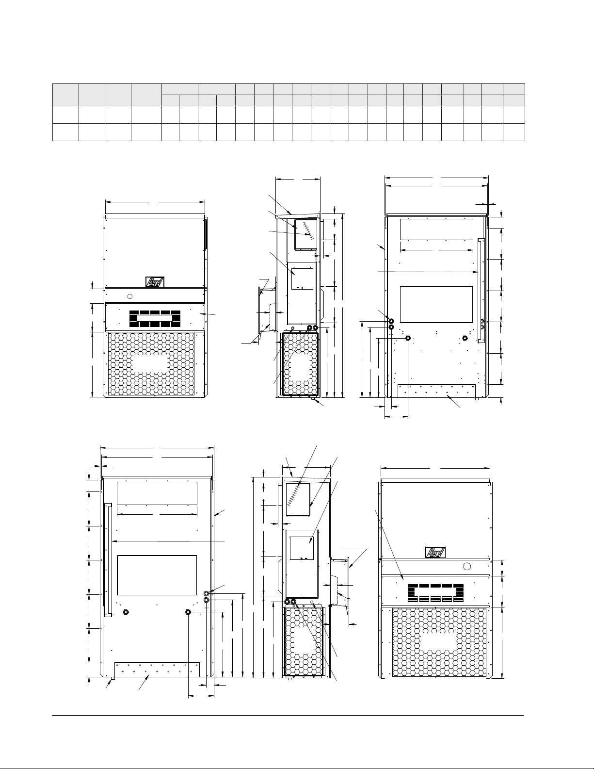
FIGURE 2
Unit Dimensions
Width
(W)
Depth
(D)
Height
(H)
Supply Return
A B C B E F G I J K L M N O P Q R S T
J18*B
J24*B 33.300 17.125 74.563 7.88 19.88 11.88 19.88 35.00 10.88 29.75 20.56 30.75 32.06 33.25 31.00 2.63 34.13 26.06 10.55 3.94 12.00 9.00
J30*B
J36*B 38.200 17.125 74.563 7.88 27.88 13.88 27.88 40.00 10.88 29.75 17.93 30.75 32.75 33.25 31.00 2.75 39.13 26.75 9.14 3.94 12.00 9.00
All dimensions are in inches. Dimensional drawings are not to scale.
J**A*
RIGHT
UNIT
J**L*
LEFT
UNIT
3"
4° Pitch
Cond.
Built In
Rain Hood
Inlet
Air
Panel
Access
Heater
Side View
Electrical
Drain
(Lockable)
Access Panel
Disconnect
Entrance
Electrical
Low Voltage
Entrance
C. Breaker/
High Voltage
Hood for ERV
models only
1.250
D
J
CH
2.13
A
I
K
7.00
Hood for full flow
ECON models only
Optional
Electrical
Entrances
Side Wall Supply Air Opening
Shipping
Location
Brackets
Return Air Opening
(Built In)
Mounting
Top Rain
Flashing
Bottom Installation
Bracket
Back View
.44
O
E
R
S
S
S
S
S
T
N
B
P
M
L
QMIS-3976 A
Electric
Heat
Front View
Air Outlet
Condenser
Filter Access Panel Standard
flush vent
door for non-
ERV
Econ.
models
1
Ventilation Air
F
W
5.88
G
1.250
I
A
C
K
2.13
H
J
N
Q
PML
O
E
.44 W
5.88
F
G
R
S
S
S
S
S
T
D
B
3"
1
Supply Air Opening
Entrances
Electrical
Drain
Inlet
Air Air Outlet
Front ViewSide View
Cond.
Bottom Back View
Condenser
Filter Access Panel
Optional
Ventilation Air
(Built In)
Brackets
Mounting
Side Wall
Location
Shipping
Flashing
Bracket
Return Air Opening
Installation Entrance
Electrical
High Voltage
Entrance
Electrical
Low Voltage
Top Rain Econ. models
non-ERV
ventdoor for
Standard flush
(Lockable)
Access Panel
Heat
Electric
Disconnect
Panel
Access
Heater
C. Breaker/
Built In
Rain Hood
4° Pitch
MIS-3972 A
7.000
Hood for full flow
ECON models
only
Hood for
ERV models
only

Manual 2100-707D
Page 11 of 39
FIGURE 3A
J18AB, J18LB, J24AB, J24LB
Mounting Instructions
12"
12"
12"
12"
12"
20"
20"
8"
201
2"
12"
9"
2"
2"
71
16 "71
16 "
5"
1"
3"
4"
Typ.
31
8"
4"
Typ.
7
8"
"
31
2
RETURN AIR
DUCT
CONTROLS AND HEATER ACCESS
Wall Opening and Hole Location View Right Side View
TOP FLASHING AT TIME OF INSTALLATION.
OPENING
MIS-3157 A
ENTIRE LENGTH OF TOP.
TOP
NOTES:
OF CAULKING ALONG
PANEL
FOAM AIR SEAL
WALL STRUCTURE
WALL
HEATER ACCESS
RAIN FLASHING
SILICONE CAULKING BE PLACED BEHIND
IS ON OPPOSITE (LEFT) SIDE.
THE SIDE MOUNTING FLANGES AND UNDER
SEAL WITH BEAD
IT IS RECOMMENDED THAT A BEAD OF
J**A UNIT SHOWN, J**L UNIT
SUPPLY AIR
SUPPLIED
Return Opening
Supply Opening
Manual 2100-707D
Page 12 of 39
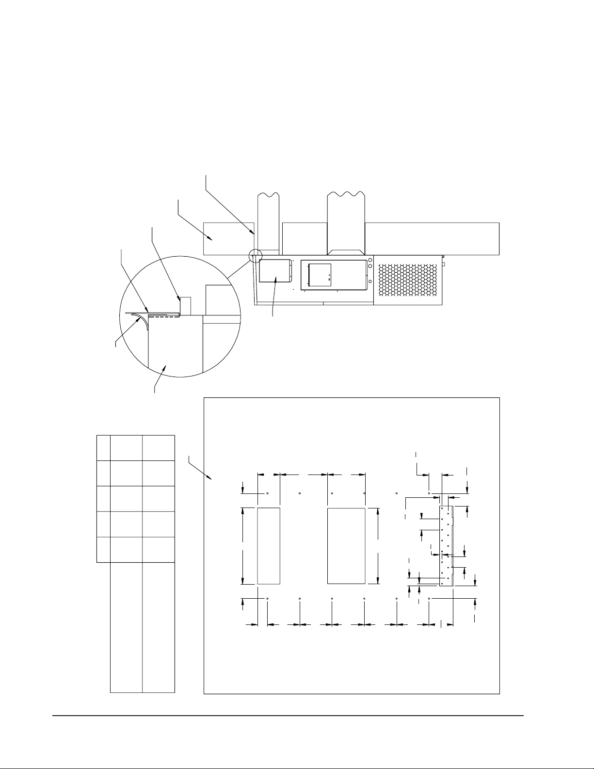
FIGURE 3B
J30AB, J30LB, J36AB, J36LB
Mounting Instructions
28"
AC
D
C
12"
12"
12"
12"
12"
B
E
14"
411
16 "411
16 "
4"
Typ.
27
8"
7
8"7
8"
4"
Typ.
31
8"
9 1
16 "
47
8"
SUPPLIED
J**A UNIT SHOWN, J**L UNIT
MIS-3158 A
SUPPLY AIR
ENTIRE LENGTH OF TOP.
TOP
OF CAULKING ALONG
PANEL
FOAM AIR SEAL
WALL STRUCTURE
RAIN FLASHING
FOUR SIDES OF SUPPLY
AIR DUCT IS REQUIRED
FROM COMBUSTABLE
MATERIALS
NOTES:
1/4" CLEARANCE ON ALL
HEATER ACCESS
TOP FLASHING AT TIME OF INSTALLATION.
THE SIDE MOUNTING FLANGES AND UNDER
SILICONE CAULKING BE PLACED BEHIND
IS ON OPPOSITE (LEFT) SIDE.
OPENING
CONTROLS AND HEATER ACCESS
DUCT
RETURN AIR
Right Side View
SEAL WITH BEAD
IT IS RECOMMENDED THAT A BEAD OF
WALL
Wall Opening and Hole Location View
REQUIRED DIMENSIONSTO MAINTAIN
Return Opening
16 7/84 5/89 7/829 7/8
17 5/83 11/165 3/88 3/828 3/8
EDCBA
COMBUSTIBLE MATERIALS
RECOMMENDED 1" CLEARANCE FROM
REQUIRED DIMENSIONSTO MAINTAIN
COMBUSTIBLE MATERIALS
1/4" MIN. CLEARANCE FROM
Supply Opening
4 1/2
Manual 2100-707D
Page 13 of 39
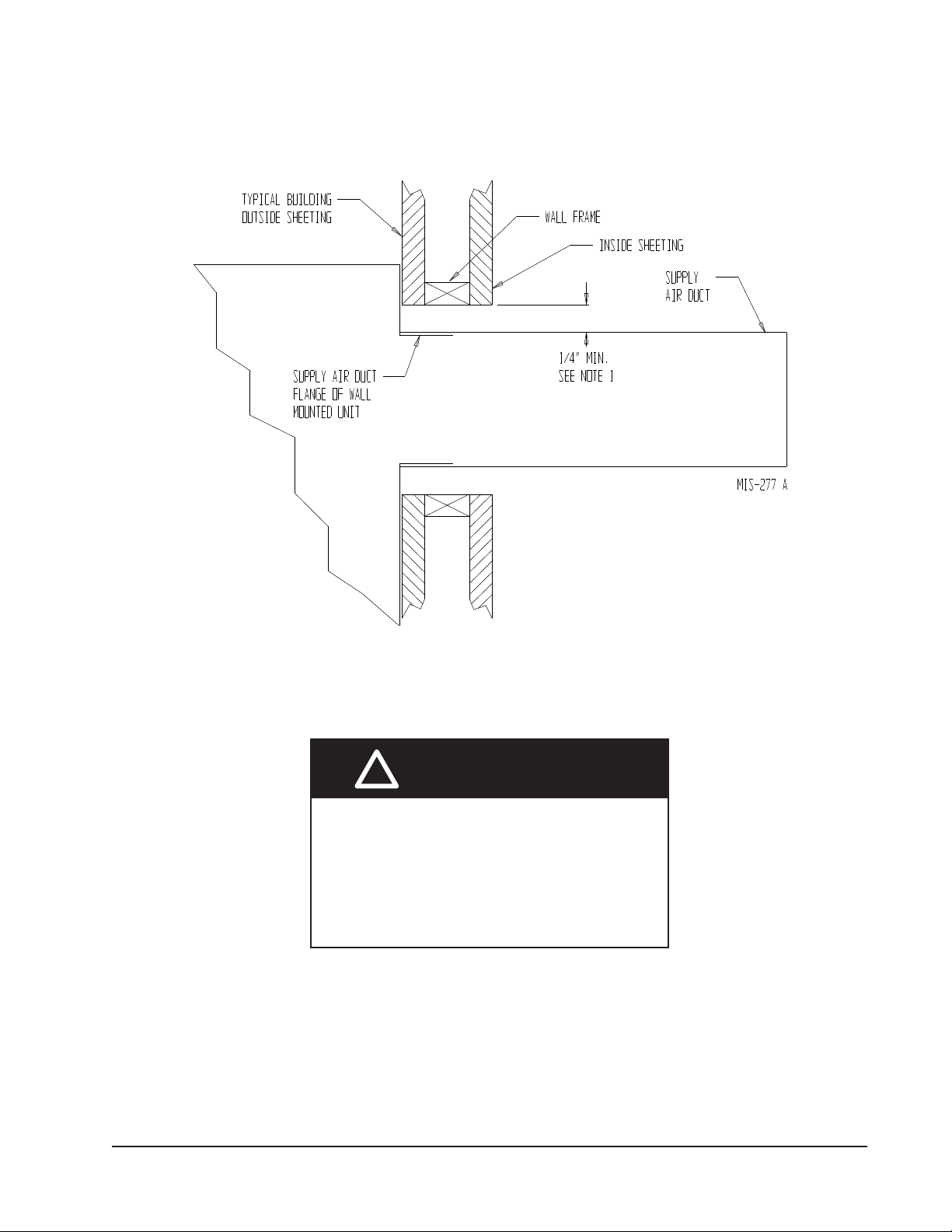
FIGURE 4
Electric Heat Clearance
J30AB, J30LB, J36AB, J36LB
NOTE 1: SIDE SECTION VIEW OF SUPPLY AIR
DUCT FOR WALL MOUNTED UNIT SHOWING 1/4"
CLEARANCE TO COMBUSTIBLE SURFACES.
Fire hazard.
Maintain minimum 1/4" clearance between the
supply air duct and combustible materials in
the rst 3' of ducting.
Failure to do so could result in re causing
damage, injury or death.
!WARNING

Manual 2100-707D
Page 14 of 39
FIGURE 5
Wall Mounting Instructions
FIGURE 6
Wall Mounting Instructions
DUCT
OPENING
RETURN AIR
SUPPLY AIR
WOOD FRAME WALL INSTALLATION
OPENING
WALL BEFORE
MOUNT ON UNIT
OPENING
BEFORE INSTALLATION
BOTTOM MOUNTING
CONCRETE BLOCK WALL INSTALLATION
BRACKET. MOUNT ON
OPENING
WOOD OR STEELSIDING
OPENING
INSTALLING UNIT.
RETURN AIR
WALL STRUCTURE
RETURN AIR
SUPPLY AIR
FACTORY SUPPLIED
RAIN FLASHING.
SUPPLY AIR
MIS-548 A
SIDE VIEW
I
A
C
K
E + 1.000
B
1.000
SUPPLY DUCT
OVER FRAME
INTERIOR FINISHED WALL
ALL AROUND DUCT
FRAMING MATERIAL
EXTERIOR FINISH WALL
OPENING
FOR ACTUAL DIMENSIONS.
2 x 4'S, 2 x 6'S &/OR
STRUCTURAL STEEL
ATTACH TO TOP
1.000" CLEARANCE
1.000" CLEARANCE
PLATE OF WALL
C
SEE UNIT DIMENSIONS, FIGURE 2,
OPENING
RETURN DUCT
2 x 6
ATTACH TO BOTTOM
OVER FRAME
PLATE OF WALL
L
THIS STRUCTURAL MEMBER
LOCATED TO MATCH STUD
SPACING FOR REST OF WALL.
A SECOND MEMBER MAY BE
REQUIRED FOR SOME WALLS.
MIS-549 B
ALL AROUND DUCT
See Figures 3A and 3B Mounting Instructions

Manual 2100-707D
Page 15 of 39
FIGURE 7
Common Wall Mounting Installations
SupplyAir
RoomAir
ReturnAir
ReturnAir
RoomAir
SupplyAir Duct
Supply Air
Supply Air
ReturnAir
SupplyAir
RoomAir
Supply Air
Supply Air
SupplyAir Duct
RoomAir
ReturnAir
throughout a single area or multiple areas. The supply air mixes
MIS-550 D
Non-Ducted Installations
Outside Wall
Adjustable SupplyGrille
Ceiling
with the room air and coolsor heats occupants and/or equipment.
Unconditioned room air is returned to the unit through a return
wall.
Fixed Blade Return Grille
sealed to
Unit is
conditioned. The supply air mixes with the room air and cools or
Indoor AreaIndoor Area
Indoor Area
Ceiling
Ceiling
plenum when installing the product.
the outer wall surface. Wall curb use may avoid resizing supply
supply air leaving supply grille and re-entering the unitreturn
room air isreturned to the unit through the return grille.Avoid
heats occupants and/or equipment in the area.Unconditioned
Non-ducted installations supply conditioned air into indoor room
directed byadjusting the 4-way supply grille to reach areas being
areas without extensive ductwork. The supply airstream is
grille without mixing with room air.
selecta curb that will meet the application requirements and also
static pressure requirementsprovided in thismanual.
provide the best unit performance and efficiency.Review duct
grille or return duct work. Avoid using restrictive duct work to
Unit
Mount Return Grille
Fixed Blade
Wall
wall.
Outside Wall
Ducted Installations
Adjustable Supply Grille
Outdoor Wall Curb Installations
sealed to
Unit
Ducted installations supply conditioned air into indoor room areas
Optional Dropped Ceiling
sealed to
Wall
WAPR11
provided with the wall curb when installing the product.
be exceeded when using a wall curb. Follow all instructions
be the correct size for the unit. Unit duct static requirements cannot
Unit Fixed Blade Return Grille
Mount
Wall
wall. Ceiling
Curb is
Outside Wall
Unit is
Wall
Mount
using solid or flexible ducts. The supply air is distributed
curb.
Optional Dropped Ceiling
reduction.Various curb options are available, and itis important to
Outside Wall
sealed to
Unit is
wall.
sealed to
Unit is
Unit
Mount
WAPR11 Indoor Sound Plenum Installations
curbs mayalso provide sound isolation and indoor area sound
and return openings thatare currentlyin an existing wall. Wall
Plenum
Outdoor Wall curbsare installed between the wall mountunit and Indoor sound plenumsare installed inside the room over the unit
return air opening.Plenum use can provide sound isolation and
indoor area sound reduction. The WAPR11 sound plenum
provides a single solution for all unit tonnage sizes. The
WAPR11 maybe installed horizontallyor vertically in the room.
Unit duct static requirements cannot be exceeded when using a
sound plenum.Follow all instructions provided with the sound
Indoor Area
Wall Curb

Manual 2100-707D
Page 16 of 39
Wiring – Main Power Wiring – Low Voltage
All 230/208V 1 phase and 3 phase equipment have
dual primary voltage transformers. All equipment leaves
the factory wired on 240V tap. For 208V operation,
reconnect from 240V to 208V tap. The acceptable
operating voltage range for the 240 and 208V taps are:
Tap: 240 Range: 253 – 216
Tap: 208 Range: 220 – 187
NOTE: The voltage should be measured at the field
power connection point in the unit and while
the unit is operating at full load (maximum
amperage operating condition).
For low voltage wiring, an 18 gauge copper, color-
coded cable is recommended. See Table 5 for more
information.
Low Voltage Connections
These units use a 24-volt AC low voltage circuit.
Cterminal is the 24VAC common and is grounded.
Gterminal is the indoor blower input.
Y1 terminal is the 1st Stage input for cooling.
Y2 terminal is the 2nd Stage compressor input for
cooling (if equipped with an economizer) or disables
Balanced Climate mode if jumper is removed on units
without an economizer (see page 18).
B/W1 terminal is the 1st stage electric heat.
W2 terminal is the 2nd stage heat (if equipped).
Aterminal is the ventilation input. This terminal
energizes any factory-installed ventilation option and
indoor blower.
Lterminal is 24 volt alarm active output.
For units equipped with an alarm relay:
1 terminal is the normally closed contact on the relay.
2 terminal is the normally open contact on the relay.
3 terminal is the common contact on the relay.
Unit Shutdown Feature (Standard on All Models)
The RT terminal is the 24VAC transformer output,
and the R terminal is the 24VAC hot terminal for the
operation of the equipment. RT and R are connected
with a brass jumper bar which can be removed and RT
and R connected to an external NC (normally closed)
contact such as a re/smoke detector that will cause
shutdown of the equipment upon activation.
Balanced Climate™ Feature (Standard on All Models)
All units are equipped with the capability of running
in Balanced Climate mode. This mode is designed to
enhance the comfort level by reducing the indoor airow
amount and extending the run time to help extract
more humidity during cooling operation. In heating
mode, the reduced airow provides a warmer supply
air temperature creating more comfortable heat. The
Refer to the unit rating plate for wire sizing information
and maximum fuse or circuit breaker size. Each
outdoor unit is marked with a “Minimum Circuit
Ampacity”. This means that the eld wiring used must
be sized to carry that amount of current. Depending
on the installed KW of electric heat, there may be two
eld power circuits required. If this is the case, the
unit serial plate will so indicate. All models are suitable
only for connection with copper wire. Each unit and/or
wiring diagram will be marked “Use Copper Conductors
Only”. These instructions must be adhered to. Refer
to the National Electrical Code (NEC) for complete
current carrying capacity data on the various insulation
grades of wiring material. All wiring must conform to
NEC and all local codes.
The electrical data lists fuse and wire sizes (75°C
copper) for all models including the most commonly used
heater sizes. Also shown are the number of eld power
circuits required for the various models with heaters.
The unit rating plate lists a “Maximum Time Delay
Relay Fuse” or circuit breaker that is to be used with
the equipment. The correct size must be used for
proper circuit protection and also to ensure that there
will be no nuisance tripping due to the momentary high
starting current of the compressor motor.
The disconnect access door on this unit may be locked
to prevent unauthorized access to the disconnect. To
convert for the locking capability, bend the tab located
in the bottom left-hand corner of the disconnect
opening under the disconnect access panel straight
out. This tab will now line up with the slot in the door.
When shut, a padlock may be placed through the hole
in the tab preventing entry.
See “Start Up” section for important information on
three phase scroll compressor start ups.
See Tables 10 and 11 on pages 29 and 30 for
electrical specications.
Electrical shock hazard.
Do not operate this equipment without an
earth ground attached and always disconnect
the remote electric power supplies before
servicing.
Electrical shock can result in serious injury or
death.
!WARNING

Manual 2100-707D
Page 17 of 39
Y1 terminal is the 24VAC input for Balanced Climate
compressor cooling operation. The Y2 terminal is the
24VAC input for compressor cooling standard operation.
Y1 and Y2 are connected with a brass jumper bar which
can be removed to enable Balanced Climate mode.
Units with an economizer will not have the brass jumper
installed. Refer to vent manuals for instructions on how
Balanced Climate works with each vent.
To operate in Balanced Climate mode, a 2-stage cooling
thermostat is required. The lower indoor airow operation
is overridden by utilizing a 2-stage thermostat. If the call
for cooling is not satised within a given time frame or
temperature differential (specied by the thermostat),
the thermostat will send a signal to Y2 which then
increases the blower speed back to the selected speed.
See pages 33 – 35 for blower speed selection options.
Refer to page 21 for additional Balanced Climate
requirements and limitations.
Ventilation Features (Optional)
See ventilation instructions provided with unit for low
voltage wiring.
Low Ambient Control (LAC)
The low ambient control is a pressure switch that is
attached to the liquid line of the system and monitors
high side pressure. Operation of the LAC occurs as
outdoor temperatures drop below 60°F. On/Off and
modulating controls are used which operate based
on pressure changes caused by outdoor temperature
changes. On/Off LAC operation cycles the condenser
fan on/off to maintain desired liquid pressure while
modulating LAC operation is factory adjusted and slows
the condenser fan speed (rpm).
Outdoor Temperature Switch and Freeze Protection
Thermostat
An outdoor temperature switch and an evaporator
freeze protection thermostat is supplied with all units
that have a low ambient control. The outdoor switch
disables Balanced Climate mode (if enabled) when the
temperature drops below 50°F. This prevents potential
evaporator coil freeze up issues. The freeze thermostat
cuts out compressor operation if the evaporator begins
to freeze up.
Alarm Relay Feature (Controls Option)
The alarm relay provides a set of NO (normally open)
and NC (normally closed) pilot duty contacts that
operate when the compressor control module locks out
compressor operation because of a high or low system
refrigerant pressure event.
TABLE 3
Humidity Controls
Part Number Predominate Features
8403-038
(H600A1014)
SPDT switching, pilot duty 50VA @ 24V;
Humidity range 20-80% RH
8403-047
(H200-10-21-10)
Electronic dehumidstat SPST closes-
on-rise; Humidity range 10-90% with
adjustable stops
TABLE 4
CO2Controllers
Part Number Predominate Features
8403-056
CO2ventilation control with digital display.
Normally Open SPST (Default: Close at
800ppm)
8403-067
Normally Open SPST relay closes-on-rise
24V dual wave length sensor. Default setting
950ppm, adjustable to 0-2000ppm
Default off setting 1000ppm, adjustable to
0-200 ppm can be calibrated
TABLE 5
Thermostat Wire Size
Transformer
VA FLA Wire Gauge Maximum Distance
In Feet
55 2.3
18 gauge
16 gauge
14 gauge
12 gauge
60
100
160
250
Manual 2100-707D
Page 18 of 39
FIGURE 8
Programmable Thermostat Connections
Thermostat W1/E AYO/D
LO/BY2Y1R GC W2
Bard #8403-060
61012
1194
12-Pin
Vent Plug 23 5 7
CO2 OUT
Optional CO2 Controller
Bard Part #8403-067
6
5
4
3
2
1
TEMP-OUT
24VAC
W3 65421R
Unit Low
Voltage
Term. Strip W2C GRT Y1 Y2 B/W1 L DA 3
mode.
8
7
6
Do not connect "A" from thermostat if optional CO2 controller is used
0-10 VDC modulating C02 control signal for modulating ventilation
control (optional for ECON only - see vent instruction manuals)
5
Change model configuration from heat pump to heat/cool. Must be configured to programmable
and fan set to be programmed fan for the "A" output to function during scheduled occupied
periods. Must be configured for multi-stage for Y1 output to be active 1st stage cooling. For
dehumidification, must be configured for "No Economizer" for YO/D to be active for humidity
control.
4
Factory installed jumper. Remove jumper and connect
to N.C fire alarm circuit if emergency shutdown required.
3
Wire not needed below 15KW.2Wire required for dehumidification models only.
1
Do not add these wires if setting up for modulating control. See note 5.
Install jumper for 1 stage electric heat on units with less than 15KW
9Factory installed jumper. Remove jumper to activate Balanced Climate™
A 2-stage thermostat is recommended for Balanced Climate mode.
W1/E
SC SC
SC
Completestat
Model #CS9B-THOA or
Model #CS9BE-THOA
W2
COM G
24V Y1 Y2 O/B L DA GND
MIS-3974
ALL VENT OPTIONS PLUG IN HERE
2
3
3
1
6
B
4
5
7
If not equipped with a ventilation option to plug in, a jumper plug must be installed.
4
2
8
9
TABLE 6
Wall Thermostats
Part Number Predominate Features
8403-060
(1120-445)
3 stage Cool; 3 stage Heat; Electronic Programmable/Non-Programmable; HP or Conventional; Auto or Manual
changeover; Dehumidication Output
CS9B-THOA
3 stage Cool, 3 stage Heat; Programmable/Non-Programmable; HP or Conventional; Auto or Manual Changeover;
Humidity Sensor w/ dehumidication; Motion Sensor w/Intelligent Learning Control; BACnet-compatible
CS9B-THOCA
3 stage Cool, 3 stage Heat; Programmable/Non-Programmable; HP or Conventional; Auto or Manual Changeover;
Humidity Sensor w/ dehumidication; CO2Sensor; Motion Sensor w/Intelligent Learning Control; BACnet-compatible
CS9BE-THOA
3 stage Cool, 3 stage Heat; Programmable/Non-Programmable; HP or Conventional; Auto or Manual Changeover; Humidity
Sensor w/ dehumidication; Motion Sensor w/Intelligent Learning Control; BACnet-compatible; Ethernet-compatible
CS9BE-THOCA
3 stage Cool, 3 stage Heat; Programmable/Non-Programmable; HP or Conventional; Auto or Manual Changeover;
Humidity Sensor w/dehumidication; CO2Sensor; Motion Sensor w/Intelligent Learning Control; BACnet-compatible;
Ethernet-compatible
8403-089
(T4 Pro)
1 stage Cool, 1 stage Heat – Heat Pump; 1 stage Cool, 1 stage Heat – Conventional; Programmable/Non-
Programmable Electronic; Auto or Manual changeover
8403-090
(T6 Pro)
2 stage Cool, 3 stage Heat – Heat Pump; 2 stage Cool, 2 stage Heat – Conventional; Programmable/Non-
Programmable Electronic; Auto or Manual changeover
8403-092
(T6 Pro Wi-Fi)
2 stage Cool, 3 stage Heat – Heat Pump; 2 stage Cool, 2 stage Heat – Conventional; Programmable/Non-
Programmable Electronic; Auto or Manual changeover; Wi-Fi
Manual 2100-707D
Page 19 of 39
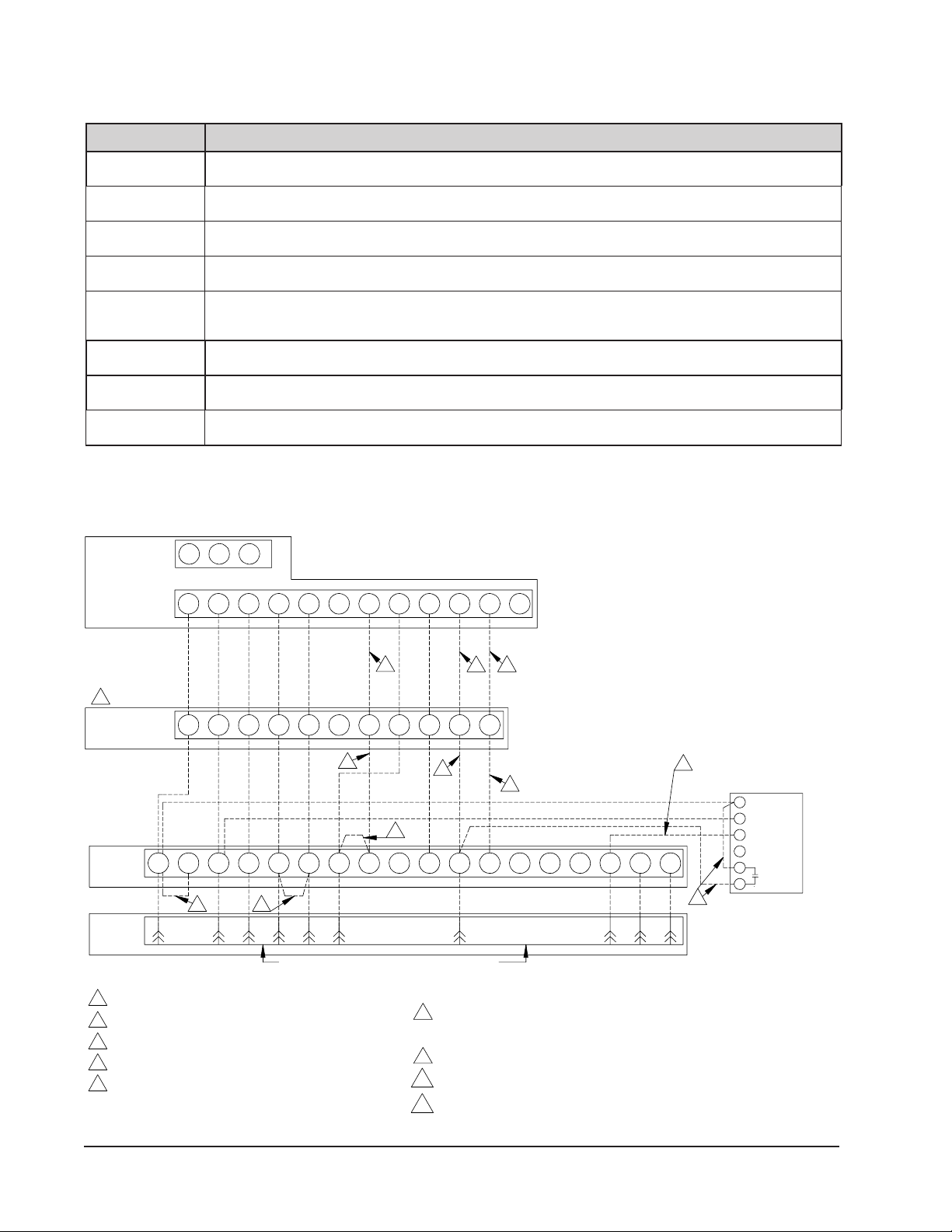
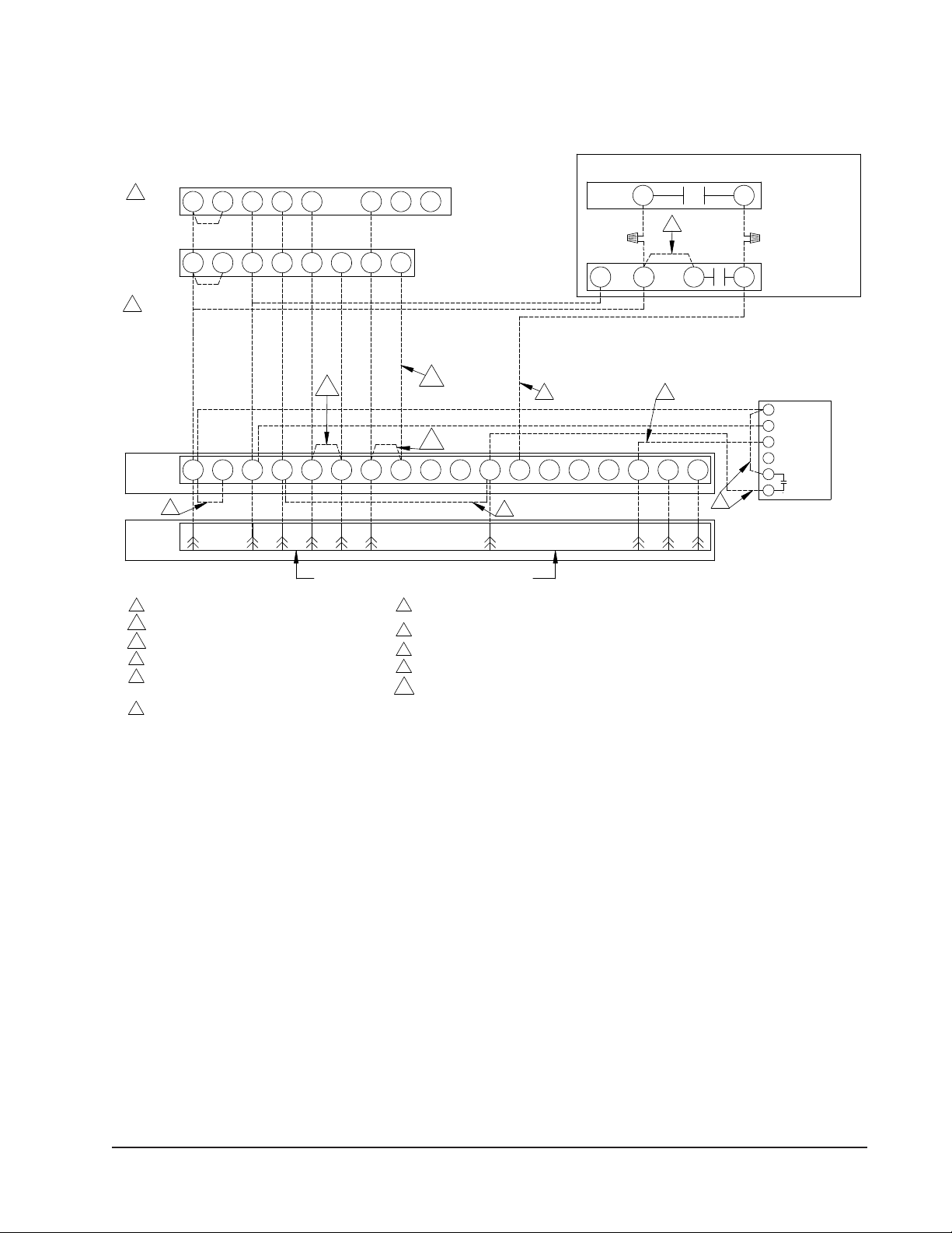
FIGURE 9
Thermostat Connections
CO2 OUT
Optional CO2 Controller
Bard Part #8403-067
6
5
4
3
2
1
TEMP-OUT
24VAC
W3 65421R
Unit Low
Voltage
Term. Strip W2C GRT Y1 Y2 B/W1 L DA 3
Factory installed jumper. Remove jumperto activate Balanced Climate™Mode.
A 2-stage thermostat is recommended for Balanced Climate mode.
10
5Do notadd these wires if setting up for modulating control. See note 7.
7
Jumperneedsadded.8
For 8403-058, change "system type", set up Function 1, From 5 (2 Heat/ 1 Coolheat Pump)
to 6 (2 Heat / 2 Cool Conventional). For 8403-059, No change required.
2B Install Jumperfor 1 stage electricheaton units with more
than 10KW.
0-10 VDC Modulating CO2 control signalfor modulating ventilation control
(Optionalfor ECON Only) - See vent installation manual.
6
For ventoperation,add jumper if optional CO2 controller is not used.
Ventwill run while blower is energized.
For ECON & CRV-V an additionalwire change is required
See install Manual.
4
Factory installed jumper. Remove jumperand connect
to N.C fire alarm circuit if emergency shutdown required.
3
Wirenotneeded below 15KW.
2A
Wire required for dehumidification models only.
1
Thermostat will not work with units equipped with economizers.9
61012
119 4
12-Pin
Vent Plug 23 5 7
9
7
8
ALL VENT OPTIONS PLUG IN HERE
4
2A
WRc CR G Y Y2 W2 4
35
6
8403-038
Electronic Humidistat
Mechanical Humidistat
3
2B
8403-058
1
(TH522OD1219/U)
or T4 Pro 8403-089 WCRc YR G O
Units With Dehumidification
B
or T6 Pro 8403-090
8403-092
8403-047
If notequipped with a ventilation option to plug in, a jumper plug must be installed.
(TH522OD1151)
8403-059
8403-057
(TH311OD1040)
6
5
10
MIS-3975 B

Manual 2100-707D
Page 20 of 39
START UP
General
1. Use separate service equipment to avoid cross
contamination of oil and refrigerants.
2. Use recovery equipment rated for R-410A
refrigerant.
3. Use manifold gauges rated for R-410A (800
psi/250 psi low).
4. R-410A is a binary blend of HFC-32 and HFC-125.
5. R-410A is nearly azeotropic—similar to R-22 and
R-12. Although nearly azeotropic, charge with
liquid refrigerant.
6. R-410A operates at 40-70% higher pressure
than R-22 and systems designed for R-22 cannot
withstand this higher pressure.
7. R-410A has an ozone depletion potential of zero,
but must be reclaimed due to its global warming
potential.
8. R-410A compressors use polyol ester oil.
9. Polyol ester oil is hygroscopic; it will rapidly absorb
moisture and strongly hold this moisture in the oil.
10. A liquid line dryer must be used—even a deep
vacuum will not separate moisture from the oil.
11. Limit atmospheric exposure to 15 minutes.
12. If compressor removal is necessary, always plug
compressor immediately after removal. Purge with
small amount of nitrogen when inserting plugs.
Topping Off System Charge
If a leak has occurred in the system, Bard
Manufacturing recommends reclaiming, evacuating
(see criteria above) and charging to the nameplate
charge. If done correctly, topping off the system charge
can be done without problems.
With R-410A, there are no signicant changes in the
refrigerant composition during multiple leaks and
recharges. R-410A refrigerant is close to being an
azeotropic blend (it behaves like a pure compound
or single component refrigerant). The remaining
refrigerant charge, in the system, may be used after
leaks have occurred and then “top-off” the charge by
utilizing the pressure charts on the inner control panel
cover as a guideline.
REMEMBER: When adding R-410A refrigerant, it must
come out of the charging cylinder/tank as a liquid to
avoid any fractionation, and to ensure optimal system
performance. Refer to instructions for the cylinder that
is being utilized for proper method of liquid extraction.
Safety Practices
1. Never mix R-410A with other refrigerants.
2. Use gloves and safety glasses. Polyol ester oils can
be irritating to the skin, and liquid refrigerant will
freeze the skin.
3. Never use air and R-410A to leak check; the
mixture may become ammable.
4. Do not inhale R-410A—the vapor attacks
the nervous system, creating dizziness, loss
of coordination and slurred speech. Cardiac
irregularities, unconsciousness and ultimate death
can result from breathing this concentration.
5. Do not burn R-410A. This decomposition produces
hazardous vapors. Evacuate the area if exposed.
6. Use only cylinders rated DOT4BA/4BW 400.
7. Never ll cylinders over 80% of total capacity.
8. Store cylinders in a cool area, out of direct
sunlight.
9. Never heat cylinders above 125°F.
10. Never trap liquid R-410A in manifold sets, gauge
lines or cylinders. R-410A expands signicantly at
warmer temperatures. Once a cylinder or line is full
of liquid, any further rise in temperature will cause
it to burst.
Important Installer Note
For improved start up performance, wash the indoor
coil with a dishwashing detergent.
High Pressure Switch
All J**A/J**L wall-mounted air conditioner series
models are supplied with a remote reset for the high
and low pressure switch. If tripped, the pressure switch
may be reset by turning the thermostat off then back
on again. High pressure switch settings: Opens 650 +/–
15 PSI, Closes 520 +/– 15 PSI.
Three Phase Scroll Compresser Start
Up Information
Scroll compressors, like several other types of
compressors, will only compress in one rotational
direction. Direction of rotation is not an issue with
single phase compressors since they will always start
and run in the proper direction.
These units require R-410A refrigerant and
polyol ester oil.
This manual suits for next models
89
Other Solair Air Conditioner manuals


Popular Air Conditioner manuals by other brands

CLIMAVENETA
CLIMAVENETA a-CHD U-2T 606+2209 OPERATING AND INSTALLATION Manual

Sealey
Sealey sac9000.V3 instruction manual

Fujitsu
Fujitsu General ASHH30KMTB Service manual

Mitsubishi Electric
Mitsubishi Electric PLA-M100EA installation manual

Dometic
Dometic FreshWell3000 installation manual

Hitachi
Hitachi RAS-E10HB instruction manual


