Solair J17A2 User manual

Manual 2100-588A
Page 1 of 29
INSTALLATION INSTRUCTIONS
WALL MOUNTED
PACKAGE AIR CONDITIONERS
MODELS
J17A2 J17L2
J24A2 J24L2
J30A2 J30L2
J36A2 J36L2
J42A2 J42L2
J48A2 J48L2
J60A2 J60L2
J70A2 J70L2
Manual : 2100-588A
Supersedes: 2100-588
File: Volume III Tab 16
Date: 03-05-14

Manual 2100-588A
Page 2 of 29
Contents
Figures
Figure 1 Fresh Air Damper Assembly.....................5
Figure 2 Unit Dimensions.......................................7
Figure 3A Mounting Instructions J17-24...................8
Figure 3B Mounting Instructions J30 – 36................9
Figure 3C Mounting Instructions J42, 48, 60, 70...... 10
Figure 4 Electric Heat Clearance ......................... 11
Figure 5 Wall Mounting Instructions.....................12
Figure 6 Wall Mounting Instructions.....................12
Figure 7 Common Wall Mounting Installations.....13
Figure 8 Basic A/C w/Opt. Elec. Heat (No Econ).....15
Figure 9 Basic A/C w/Opt. Elec. Heat (EIFM Econ).18
Figure 10 Basic A/C w/Opt. Elec. Heat (Newer Econ)18
Figure 11 Fan Blade Setting...................................21
Tables
Table 1 Fan Blade Dimensions...........................21
Table 2 Refrigerant Charge.................................21
Table 3 Refrigerant Charge.................................21
Table 4 Cooling Pressure....................................22
Table 5 Electrical Specications J**A..................24
Table 6 Electrical Specications J**L..................24
Table 7 Recommended Airow ...........................25
Table 8 Indoor Blower Performance ...................25
Table 9 Maximum ESP Electric Heat Only..........25
Table 10 Electric Heat...........................................26
Table 11A OptionalAccessories — Right Hand......27
Table 11B Optional Accessories — Left Hand ............28
Table 12 Vent & Control Options...........................29
Getting Other Information and Publications 3
Wall Mount General Information
Wall Mount Model Nomenclature..............................4
Shipping Damage .....................................................4
General .................................................................4
Duct Work.................................................................5
Filters .................................................................5
Fresh Air Intake.........................................................5
Condensate Drain ....................................................5
Installation Instructions
Wall Mounting Information ........................................6
Mounting the Unit......................................................6
Clearances Required................................................6
Minimum Clearances................................................6
Wiring – Main Power...............................................14
Wiring – Low Voltage Wiring ...................................14
Start Up
General ...............................................................18
Topping Off System Charge....................................18
Safety Practices......................................................18
Important Installer Note...........................................19
High Pressure Switch..............................................19
Three Phase Scroll Compressor.............................19
Phase Monitor.........................................................19
Condenser Fan Operation ......................................19
Service Hints...........................................................19
Sequence of Operation...........................................20
Compressor Control Module...................................20
Adjustments............................................................20
Pressure Service Ports...........................................20
Troubleshooting
Fan Blade Setting Dimensions................................21
R-410A Refrigerant Charge ....................................21
Removal of Fan Shroud..........................................21

Manual 2100-588A
Page 3 of 29
GETTING OTHER INFORMATION AND PUBLICATIONS
These publications can help you install the air
conditioner or heat pump. You can usually nd these
at your local library or purchase them directly from the
publisher. Be sure to consult current edition of each
standard.
National Electrical Code.......................ANSI/NFPA 70
Standard for the Installation............... ANSI/NFPA 90A
of Air Conditioning and Ventilating Systems
Standard for Warm Air....................... ANSI/NFPA 90B
Heating and Air Conditioning Systems
Load Calculation for ......................... ACCA Manual J
Residential Winter and Summer Air Conditioning
Duct Design for Residential...............ACCA Manual D
Winter and Summer Air Conditioning and Equipment
Selection
FOR MORE INFORMATION, CONTACT
THESE PUBLISHERS:
ACCA Air Conditioning Contractors ofAmerica
1712 New Hampshire Ave. N.W.
Washington, DC 20009
Telephone: (202) 483-9370
Fax: (202) 234-4721
ANSI American National Standards Institute
11 West Street, 13th Floor
New York, NY 10036
Telephone: (212) 642-4900
Fax: (212) 302-1286
ASHRAE American Society of Heating, Refrigeration
and Air Conditioning Engineers, Inc.
1791 Tullie Circle, N.E.
Atlanta, GA 30329-2305
Telephone: (404) 636-8400
Fax: (404) 321-5478
NFPA National Fire ProtectionAssociation
Batterymarch Park
P.O. Box 9101
Quincy, MA 02269-9901
Telephone: (800) 344-3555
Fax: (617) 984-7057
Manual 2100-588A
Page 4 of 29
WALL MOUNT GENERAL INFORMATION
AIR CONDITIONER WALL MOUNT MODEL NOMENCLATURE
J 42 A 2 – A 10 X X X X X J
NOTE: Vent option X is without exhaust capability. May require separate eld supplied barometric relief in building.
SHIPPING DAMAGE
Upon receipt of equipment, the carton should be
checked for external signs of shipping damage. If
damage is found, the receiving party must contact
the last carrier immediately, preferably in writing,
requesting inspection by the carrier’s agent.
GENERAL
The equipment covered in this manual is to be installed
by trained, experienced service and installation
technicians.
The refrigerant system is completely assembled and
charged. All internal wiring is complete.
The unit is designed for use with or without duct work.
Flanges are provided for attaching the supply and return
ducts.
These instructions explain the recommended method
to install the air cooled self-contained unit and the
electrical wiring connections to the unit.
These instructions and any instructions packaged with
any separate equipment required to make up the entire
air conditioning system should be carefully read before
beginning the installation. Note particularly “Starting
Procedure” and any tags and/or labels attached to the
equipment.
While these instructions are intended as a general
recommended guide, they do not supersede any
national and/or local codes in any way. Authorities
having jurisdiction should be consulted before the
installation is made. See Page 3 for information on
codes and standards.
Size of unit for a proposed installation should be based
on heat loss calculation made according to methods
of Air Conditioning Contractors of America (ACCA).
The air duct should be installed in accordance with the
Standards of the National Fire Protection Association
for the Installation of Air Conditioning and Ventilating
Systems of Other Than Residence Type, NFPA No.
90A, and Residence Type Warm Air Heating and Air
Conditioning Systems, NFPA No. 90B. Where local
regulations are at a variance with instructions, installer
should adhere to local codes.
KW
MODEL NUMBER CONTROL MODULES
(See Spec. Sheet S3438,
S3439 &/or S3440)
VOLTS & PHASE
A - 230/208/60/1
B - 230/208/60/3
C - 460/60/3
REVISIONS
VENTILATION OPTIONS
X - Barometric Fresh Air Damper (Standard)
See Vent & Control Options Table 12 FILTER OPTIONS
P - Two Inch Pleated
COLOR OPTIONS
X - Beige (Standard)
COIL OPTIONS
X - Standard
OUTLET OPTIONS
X - Front (Standard)
CAPACITY
17 - 1
½
Ton
24 - 2 Ton
30 - 2
½ Ton
36 - 3 Ton
42 - 3
½
Ton
48 - 4 Ton
60 - 5 Ton
70 - 6 Ton A - Right Hand Air Conditioner
L - Left Hand Air Conditioner
Manual 2100-588A
Page 5 of 29
DUCT WORK
All duct work, supply and return, must be properly sized
for the design airow requirement of the equipment.
Air Conditioning Contractors of America (ACCA) is an
excellent guide to proper sizing. All duct work or portions
thereof not in the conditioned space should be properly
insulated in order to both conserve energy and prevent
condensation or moisture damage.
Refer to Maximum ESP of operation Electric Heat Table 9.
Design the duct work according to methods given by the Air
Conditioning Contractors of America (ACCA). When duct
runs through unheated spaces, it should be insulated with a
minimum of one inch of insulation. Use insulation with a
vapor barrier on the outside of the insulation. Flexible joints
should be used to connect the duct work to the equipment in
order to keep the noise transmission to a minimum.
Models J17 - J24 as approved for zero inch clearance to
the supply duct. For model series J30, J36, J42, J48, J60
and J70 a 1/4 inch clearance to combustible material for
the rst three feet of duct attached to the outlet air frame is
required. See Wall Mounting Instructions and Figures 3A
- 3C for further details.
Ducts through the walls must be insulated and all joints taped
or sealed to prevent air or moisture entering the wall cavity.
Some installations may not require any return air duct. A
metallic return air grille is required with installations not
requiring a return air duct. The spacing between louvers on
the grille shall not be larger than 5/8 inch.
Any grille that meets with 5/8 inch louver criteria may be
used. It is recommended that Bard Return Air Grille Kit
RG2 through RG5 or RFG2 through RFG5 be installed
when no return duct is used. Contact distributor or factory
for ordering information. If using a return air lter grille,
lters must be of sufcient size to allow a maximum
velocity of 400 fpm.
NOTE: If no return air duct is used, applicable installation
codes may limit this cabinet to installation only in a
single story structure.
FILTERS
A two-inch pleated lter is standard with each
unit. The internal lter brackets are adjustable to
accommodate the 2-inch lter by bending two (2) tabs
down on each side of the lter support bracket.
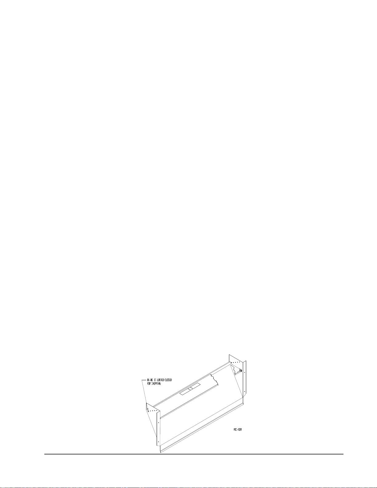
FRESH AIR INTAKE
All units are built with fresh air inlet slots punched in
the service door.
If the unit is equipped with a fresh air damper assembly,
the assembly is shipped already attached to the unit.
The damper blade is locked in the closed position.
To allow the damper to operate, the maximum and
minimum blade position stops must be installed. See
Figure 1.
All capacity, efciency and cost of operation
information is based upon the fresh air blank-off plate
in place and is recommended for maximum energy
efciency.
The blank-off plate is available upon request from the
factory and is installed in place of the fresh air damper
shipped with each unit.
CONDENSATE DRAIN
A plastic drain hose extends from the drain pan at
the top of the unit down to the unit base. There are
openings in the unit base for the drain hose to pass
through. In the event the drain hose is connected to a
drain system of some type, it must be an open or vented
type system to assure proper drainage.
FIGURE 1
FRESH AIR DAMPER
Manual 2100-588A
Page 6 of 29
Clearances Required for Service Access
and Adequate Condenser Airow
MODELS LEFT
SIDE RIGHT
SIDE DISCHARGE
SIDE
J17A, J24A, J30A, J36A 15" 20" 10'
J17L, J24L, J30L, J36L 20" 15" 10'
J42A, J48A, J60A, J70A 20" 20" 10'
J42L, J48L, J60L, J70L 20" 20" 10'
Minimum Clearances Required to
Combustible Materials
MODELS SUPPLY AIR DUCT
FIRST THREE FEET CABINET
J17A, L / J24A, L 0" 0"
J30A, L / J36A, L 1/4" 0"
J42A, L / J48A, L
J60A, L / J70A, L 1/4" 0"
NOTE: For side by side installation of two (2) J**A models there
must be 20" between units. This can be reduced to 15" by using a
J**L model (left side compressor and controls) for the left unit and
JA (right side compressor and controls) for right unit.
See J**A Specication S3438 & J**L Specication S3439 & J70
Specication S3440 (Right & Left-Hand).
INSTALLATION INSTRUCTIONS
WARNING
Failure to provide the 1/4 inch clearance
between the supply duct and a combustible
surface for the rst 3 feet of duct can result in
re causing damage, injury or death.
WALL MOUNTING INFORMATION
1.
Two holes for the supply and return air openings must
be cut through the wall as shown in Figures 3A-3C.
2. On wood frame walls, the wall construction must be
strong and rigid enough to carry the weight of the
unit without transmitting any unit vibration.
3. Concrete block walls must be thoroughly inspected
to insure that they are capable of carrying the
weight of the installed unit.
MOUNTING THE UNIT
1. These units are secured by wall mounting brackets
which secure the unit to the outside wall surface at
both sides. A bottom mounting bracket, attached
to skid for shipping, is provided for ease of
installation, but is not required.
2. Models J17 and J24 are suitable for 0 inch clearance
to the unit and the supply air duct. Models
J30-J70 require 1/4 inch clearance to combustible
materials to the supply air duct ange and the rst
3 feet of supply air duct. However, it is generally
recommended that a 1-inch clearance is used for
ease of installation and maintaining the required
clearance to combustible material. See Figure 3 for
details on opening sizes.
3. Locate and mark lag bolt locations and bottom
mounting bracket location. See Figures 3A - 3C.
4. Mount bottom mounting bracket.
5. Hook top rain ashing, attached to front - right of
supply ange for shipping, under back bend of top.
6. Position unit in opening and secure with 5/16 lag
bolts; use 7/8 inch diameter at washers on the lag
bolts.
7. Secure rain ashing to wall and caulk across entire
length of top. See Figures 3A - 3C.
8. For additional mounting rigidity, the return air
and supply air frames or collars can be drilled
and screwed or welded to the structural wall itself
(depending upon wall construction). Be sure to
observe required clearance if combustible wall.
9. On side-by-side installations, maintain a minimum
of 20 inches clearance on right side to allow access
to control panel and heat strips, and to allow proper
airow to the outdoor coil. Additional clearance
may be required to meet local or national codes.

Manual 2100-588A
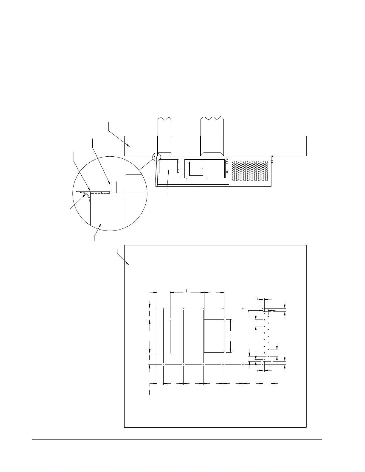
Page 7 of 29
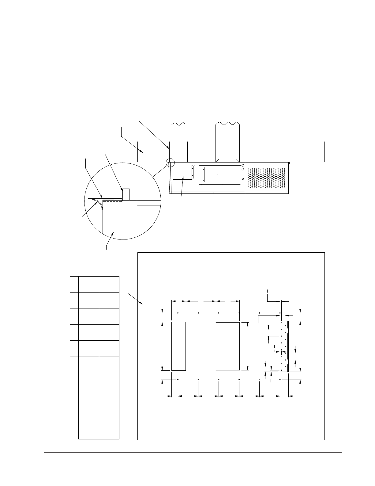
Dimensions of Basic Unit for Architectural and Installation Requirements (Nominal)
MODEL WIDTH
(W) DEPTH
(D) HEIGHT
(H) SUPPLY RETURN
A B C B E F G I J K L M N O P Q R S T
J17A, L
J24A, L 33.300 17.125 70.563 7.88 19.88 11.88 19.88 35.00 11.00 25.75 20.56 26.75 28.06 29.25 27.00 2.63 34.13 22.06 10.55 4.19 12.00 5.00
J30A, L
J36A, L 38.200 17.125 70.563 7.88 27.88 13.88 27.88 40.00 11.00 25.75 17.93 26.75 28.75 29.25 27.00 2.75 39.19 22.75 9.14 4.19 12.00 5.00
J42A, L
J48A, L
J60A, L
J70A, L
42.075 22.432 84.875 9.88 29.88 15.88 29.88 43.88 13.63 31.66 30.00 32.68 26.94 34.69 32.43 3.37 42.88 23.88 10.00 1.44 16.00 1.88
1.250
H
A
C
K
2.13
3"
J
N
E
PM
Q
B
O
.44 W
5.88
F
G
R
S
S
S
S
S
T
D
L
I
1
Bracket
Installation
Air Outlet
Shipping
Drain
Air
Location
Entrances
Bottom
models
Side View
Inlet
Flashing
High Voltage
Supply Air Opening
Condenser
Cond.
Access
Panel
BackView
Side Wall
Mounting
Brackets
Optional
Heater
Return Air Opening
Entrance
Electrical
(Built In)
Ventilation Air
models.
Electrical
4° Pitch
Filter Access Panel
Top Rain
Low Voltage
Electrical
Entrance
Standard flush
vent door for
Access Panel
(Lockable)
non-ERV/Econ.
Disconnect
Electric
Heat
Front View
C. Breaker/
Built In
Rain Hood
Hood for
ECONWMT
MIS-3124 B
Hood used on
ERV and
ECONWMS only
11"
3"
7.88 1.00
11"
31.88
Filter Access Panel
Air Outlet
Front View
Condenser
Standard
flush vent
door for
non-ERV/
Econ.
models
Ventilation Air
W
5.88
F
G
1
1
Heat
models.
1
Electric
Hood for
ECONWMT
MIS-2487 H
(Lockable)
Built In
Rain Hood
4° Pitch
Entrance
High Voltage
Entrance
Access Panel
Low Voltage
Disconnect
Heater
Panel
Access
Air
Inlet
Drain
Cond.
Electrical
Side View
Electrical
C. Breaker/
Hood for ERV and
ECONWMS models
only
1.250
H
A
I
D
J
2.13
C
K
Electrical
Side Wall
Entrances
Mounting
Optional
Supply Air Opening
(Built In)
Shipping
Location
Brackets
Return Air Opening
Top Rain
Flashing
Bottom Installation
Bracket
BackView
T
B
M
O
E
R
S
S
S
S
S
P
.44
NQ
L
j Optional top outlet (factory installed only) for J30A and J36Amodels only.
FIGURE 2
All dimensions are in inches. Dimensional drawings are not to scale.
J**A
RIGHT
UNIT
J**L
LEFT
UNIT
j
jj
Manual 2100-588A
Page 8 of 29
FIGURE 3A
J17A2, J17L2, J24A2, J24L2
MOUNTING INSTRUCTIONS
12"
12"
12"
12"
12"
20"
20"
1"
3"
4"
Typ.
8"
201
2"
12"
1"
31
8"
4"
Typ.
5"
7
8"
313
16"
2" 2"
71
16"1
16"7
CONTROLS AND HEATER ACCESS
NOTES:
TOP
TOP FLASHING AT TIME OF INSTALLATION.
OPENING
MIS-3157
ENTIRE LENGTH OF TOP.
RETURN AIR
DUCT
Wall Opening and Hole Location View Right Side View
OF CAULKING ALONG
PANEL
FOAM AIR SEAL
WALL STRUCTURE
WALL
HEATER ACCESS
RAIN FLASHING
SILICONE CAULKING BE PLACED BEHIND
IS ON OPPOSITE (LEFT) SIDE.
THE SIDE MOUNTING FLANGES AND UNDER
SEAL WITH BEAD
IT IS RECOMMENDED THAT A BEAD OF
W**A UNIT SHOWN, W**LUNIT
SUPPLY AIR
SUPPLIED
Return Opening
Supply Opening
Manual 2100-588A
Page 9 of 29
FIGURE 3B
J30A2, J30L2, J36A2, J36L2
MOUNTING INSTRUCTIONS
28"
A
C
D
C
12"
12"
12"
12"
12"
5 1
16"
B
E
14"
411
16"411
16"
4"
Typ.
27
8"
7
8"7
8"
4"
Typ. 7
8"
31
8"
W*RUNIT SHOWN, W*LUNIT
MIS-3158
ENTIRE LENGTH OF TOP.
SUPPLIED
SUPPLY AIR
TOP
OF CAULKING ALONG
PANEL
FOAM AIR SEAL
WALL STRUCTURE
RAIN FLASHING
FOUR SIDES OF SUPPLY
AIR DUCT IS REQUIRED
FROM COMBUSTABLE
MATERIALS
NOTES:
1/4" CLEARANCE ON ALL
HEATER ACCESS
TOP FLASHING AT TIME OF INSTALLATION.
THE SIDE MOUNTING FLANGES AND UNDER
SILICONE CAULKING BE PLACED BEHIND
IS ON OPPOSITE (LEFT) SIDE.
OPENING
CONTROLS AND HEATER ACCESS
DUCT
RETURN AIR
Right Side View
SEAL WITH BEAD
IT IS RECOMMENDED THAT A BEAD OF
WALL
Wall Opening and Hole Location View
Return Opening
16 7/84 7/164 5/89 7/829 7/8
17 5/8311/165 3/88 3/8
28 3/8
EDCBA
COMBUSTIBLE MATERIALS
RECOMMENDED 1" CLEARANCE FROM
REQUIRED DIMENSIONS TO MAINTAIN
COMBUSTIBLE MATERIALS
1/4" MIN. CLEARANCE FROM
REQUIRED DIMENSIONS TO MAINTAIN
Supply Opening

Manual 2100-588A
Page 10 of 29
FIGURE 3C
J42A2, J42L2, J48A2, J48L2, J60A2, J60L2, J70A2, J70L2
MOUNTING INSTRUCTIONS
D
16"
16"
16"
16"
16"
17
8"61
2" 61
2"21
8"
7
8"
1" 3"
4"
Typ.
4"
Typ.
61
2"30"
E
16"
A CC
31
8"
B
Wall Opening and Hole Location View
RETURN AIR
1
REQUIRED DIMENSIONS TO MAINTAIN
1/4" MIN. CLEARANCE FROM
COMBUSTIBLE MATERIALS
REQUIRED DIMENSIONS TO MAINTAIN 29
DUCT
COMBUSTIBLE MATERIALS
A B C DE
30 1/2 10 1/2 6 1/4 1 1/4 29 3/4
32 12 5 1/2 2
NOTES:
WALL STRUCTURE
1
SUPPLY AIR
IT IS RECOMMENDED THAT A BEADOF
OPENING
Right Side View
RAIN FLASHING
SILICONE CAULKING BE PLACED BEHIND
RECOMMENDED 1" CLEARANCE FROM
THE SIDE MOUNTING FLANGES AND UNDER
TOP FLASHING AT TIME OFINSTALLATION.
TOP.
PANEL
HEATER ACCESS
FOUR SIDES OFSUPPLY
AIRDUCTIS REQUIRED
FROM COMBUSTABLE
WALL 1/4" CLEARANCE ONALL
MATERIALS
Supply Opening
FOAMAIRSEAL
SUPPLIED
SEAL WITH BEAD
OF CAULKING ALONG
ENTIRE LENGTH OF
TOP
1
Return Opening
MIS-416 E
Dimension is 21" on 95" tall units.
2
Dimension is 10" on T48H1 & T60H1.
2
Dimension is 6" on T48H1 & T60H1.
3
3
Manual 2100-588A
Page 11 of 29
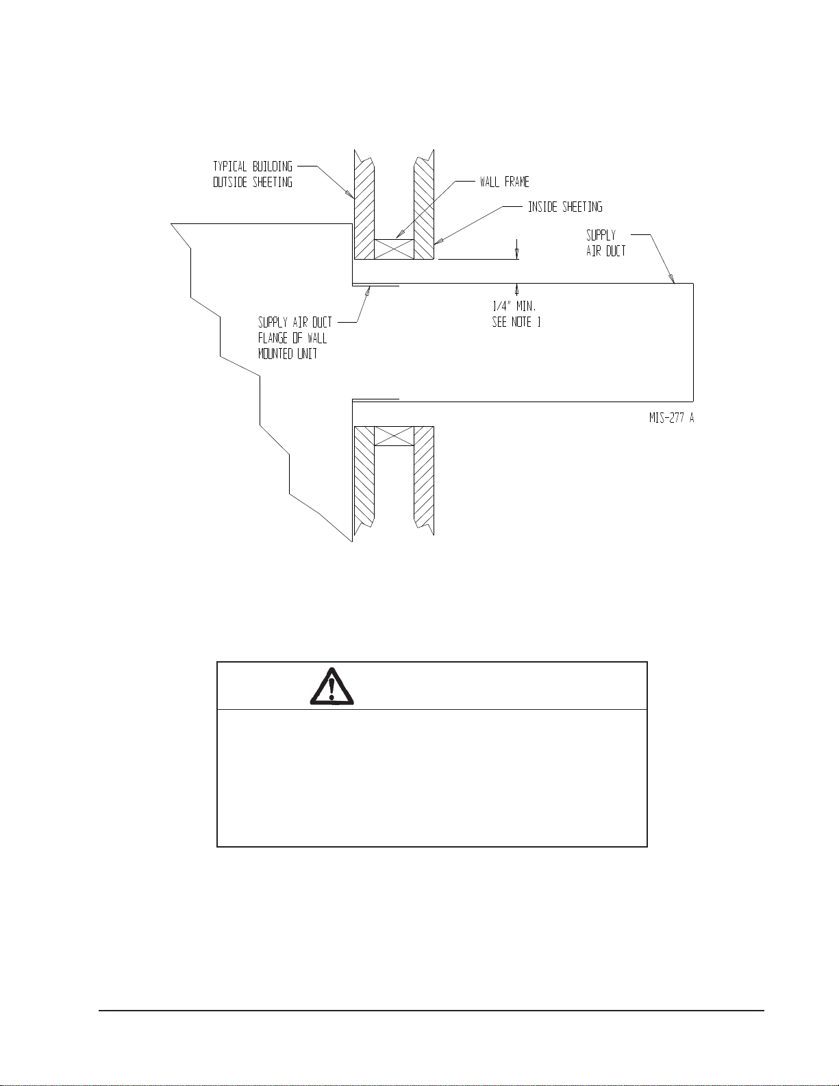
FIGURE 4
ELECTRIC HEAT CLEARANCE
J30A2, J30L2, J36A2, J36L2, J42A2, J42L2, J48A2, J48L2, J60A2, J60L2, J70A2, J70L2
WARNING
A minimum of 1/4 inch clearance must be maintained between
the supply air duct and combustible materials. This is required for
the rst 3 feet of ducting.
It is important to insure that the 1/4 inch minimum spacing is
maintained at all points.
Failure to do this could result in overheating the combustible
material and may result in a re causing damage, injury or death.
NOTE 1: SIDE SECTION VIEW OF SUPPLYAIR
DUCT FOR WALL MOUNTED UNIT SHOWING 1/4
INCH CLEARANCE TO COMBUSTIBLE SURFACES.

Manual 2100-588A
Page 12 of 29
FIGURE 5
WALL MOUNTING INSTRUCTIONS
FIGURE 6
WALL MOUNTING INSTRUCTIONS
DUCT
OPENING
RETURN AIR
SUPPLY AIR
WOOD FRAME WALL INSTALLATION
OPENING
WALL BEFORE
MOUNT ON UNIT
OPENING
BEFORE INSTALLATION
BOTTOM MOUNTING
CONCRETE BLOCK WALL INSTALLATION
BRACKET. MOUNT ON
OPENING
WOOD OR STEELSIDING
OPENING
INSTALLING UNIT.
RETURN AIR
WALL STRUCTURE
RETURN AIR
SUPPLY AIR
FACTORY SUPPLIED
RAIN FLASHING.
SUPPLY AIR
MIS-548 A
SIDE VIEW
I
A
C
K
E + 1.000
B
1.000
SUPPLY DUCT
OVER FRAME
INTERIOR FINISHED WALL
ALL AROUND DUCT
FRAMING MATERIAL
EXTERIOR FINISH WALL
OPENING
FOR ACTUAL DIMENSIONS.
2 x 4'S, 2 x 6'S &/OR
STRUCTURAL STEEL
ATTACH TO TOP
1.000" CLEARANCE
1.000" CLEARANCE
PLATE OF WALL
C
SEE UNIT DIMENSIONS, FIGURE 2,
OPENING
RETURN DUCT
2 x 6
ATTACH TO BOTTOM
OVER FRAME
PLATE OF WALL
L
THIS STRUCTURAL MEMBER
LOCATED TO MATCH STUD
SPACING FOR REST OF WALL.
A SECOND MEMBER MAY BE
REQUIRED FOR SOME WALLS.
MIS-549 B
ALL AROUND DUCT
SEE FIGURES 3A-3C – MOUNTING INSTRUCTIONS
Manual 2100-588A
Page 13 of 29
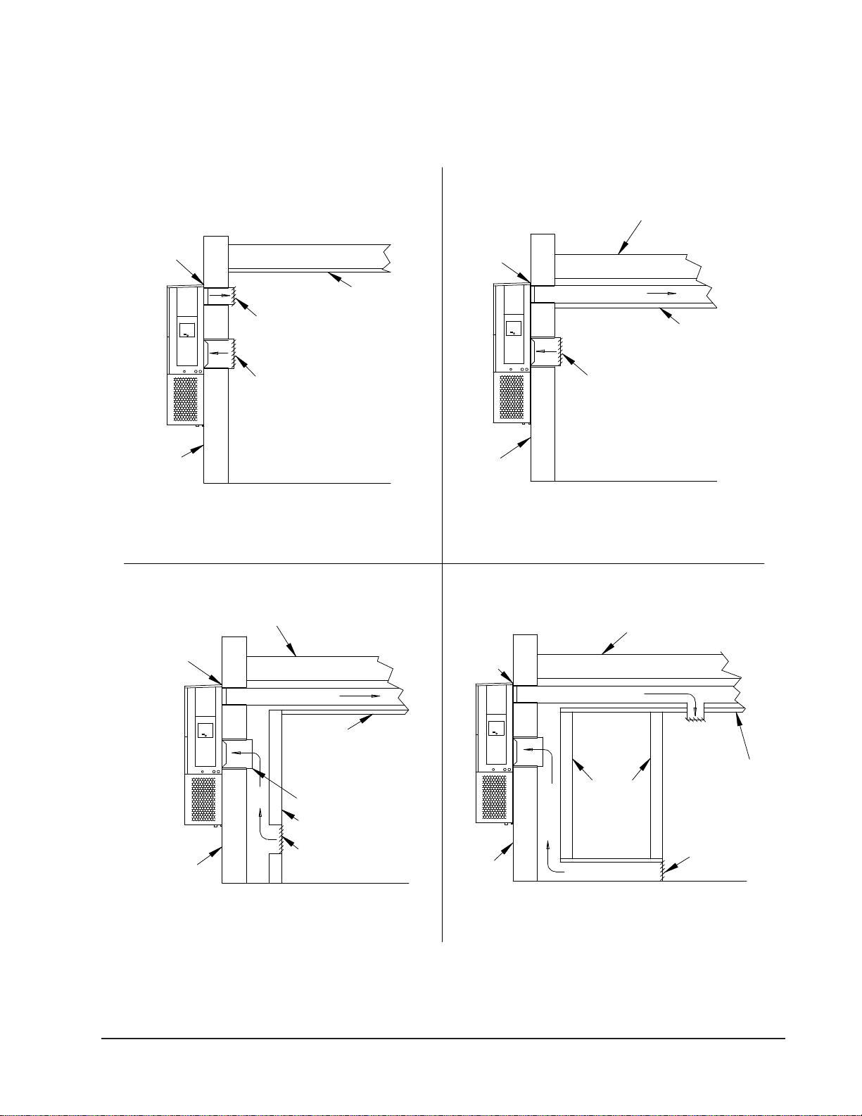
FIGURE 7
COMMON WALL MOUNTING INSTALLATIONS
LOWERED
RAISED FLOOR
RAFTERS
SUPPLY AIR
CEILING SURFACE
WALL SLEEVE
RETURN AIR
CLOSET WALL
GRILLE
FLASHING
RETURN AIR
FLASHING
SUPPLY DUCT MAYBE LOCATED INANATTIC
OR BELOW CEILING RAFTERS AS SHOWN
SUPPLY DUCT MAY BE LOCATED INANATTIC
SURFACE
RAFTERS
FINISHED CEILING
SUPPLY AIRDUCT
WALL
OPENING W/ GRILLE
SUPPLY DUCT MAYBE LOCATED INANATTIC
OR BELOW CEILING RAFTERS AS SHOWN
CEILING
RAIN
RETURN AIR
SLEEVE
WALL
SUPPLY AIRDUCT
RAFTERS
RAFTERS
RETURN AIR
OPENING W/ GRILLE
RAIN
FALSE WALL INSTALLATION
DUCTED SUPPLY
GRILLE
OUTSIDE
SPACE
FALSE WALL
RETURN AIR GRILLE
OUTSIDE
OR BELOW CEILING RAFTERS AS SHOWN
FINISHED CEILING SURFACE
RAIN
FLASHING
RAIN
FLASHING
RETURN AT UNITNO DUCT
WALL
SUPPLY AIRDUCT
CLOSETINSTALLATION
RETURN AIR
FINISHED
FINISHED CEILING SURFACE
MIS-550 B
FREE AIR FLOW
OUTSIDE
WALL
OUTSIDE
WALL
SUPPLY AIRDUCT
W/ GRILLE

Manual 2100-588A
Page 14 of 29
WIRING – MAIN POWER
Refer to the unit rating plate for wire sizing information
and maximum fuse or “HACR” type circuit breaker
size. Each outdoor unit is marked with a “Minimum
Circuit Ampacity”. This means that the eld wiring
used must be sized to carry that amount of current.
Depending on the installed KW of electric heat, there
may be two eld power circuits required. If this is the
case, the unit serial plate will so indicate. All models
are suitable only for connection with copper wire. Each
unit and/or wiring diagram will be marked “Use Copper
Conductors Only”. These instructions must be adhered
to. Refer to the National Electrical Code (NEC) for
complete current carrying capacity data on the various
insulation grades of wiring material. All wiring must
conform to NEC and all local codes.
The electrical data lists fuse and wire sizes (75° C
copper) for all models including the most commonly
used heater sizes. Also shown are the number of eld
power circuits required for the various models with
heaters.
The unit rating plate lists a “Maximum Time Delay
Relay Fuse” or “HACR” type circuit breaker that is to
be used with the equipment. The correct size must be
used for proper circuit protection and also to assure that
there will be no nuisance tripping due to the momentary
high starting current of the compressor motor.
The disconnect access door on this unit may be locked
to prevent unauthorized access to the disconnect. To
convert for the locking capability, bend the tab located
in the bottom left-hand corner of the disconnect
opening under the disconnect access panel straight
out. This tab will now line up with the slot in the door.
When shut, a padlock may be placed through the hole
in the tab preventing entry.
See “Start Up” section for important information on
three phase scroll compressor start ups.
See Tables 5 & 6 for Electrical Specications.
WIRING – LOW VOLTAGE WIRING
All 230/208V, 1 phase and 3 phase equipment have
dual primary voltage transformers. All equipment
leaves the factory wired on 240V tap. For 208V
operation, reconnect from 240V to 208V tap. The
acceptable operating voltage range for the 240 and
208V taps are:
TAP RANGE
240 253 – 216
208 220 – 187
NOTE: Thevoltageshouldbemeasuredattheeld
power connection point in the unit and while
the unit is operating at full load (maximum
amperage operating condition).
An 18 gauge copper, color-coded thermostat cable is
recommended. The connection points are shown in this
Manual. See Table below.
Low Voltage Connection
These units use a 24-volt AC low voltage circuit. The
“RT” terminal is the 24V transformer output, and the
“R” terminal is the 24VAC hot terminal for the operation
of the equipment. “RT” and “R” are connected with
brass jumper bar which can be removed and “RT” and
“R” connected to external NC (normally closed) contact
such as a re/smoke detector that will cause immediate
shutdown of the equipment upon activation.
“C” terminal is grounded.
“G” terminal is the fan input.
“Y” terminal is the compressor input for cooling.
“W1” terminal is the 1st stage electric heat.
“W2” terminal is the 2nd stage heat (if equipped).
“A” terminal is the ventilation input. This terminal
energizes any factory installed ventilation option. See
Table 14 for options.
NOTE: Models with “J” Control Module, “3”
terminal is used along with “1” and “2” for the alarm
relay.
LOW VOLTAGE CONNECTIONS
FOR DDC CONTROL
Fan Only Energize G
Cooling Mode Energize Y, G
1st Stage Heating Energize W1
2nd Stage Heating
(if employed) Energize W1, W2
Ventilation Energize G, A
Manual 2100-588A
Page 15 of 29
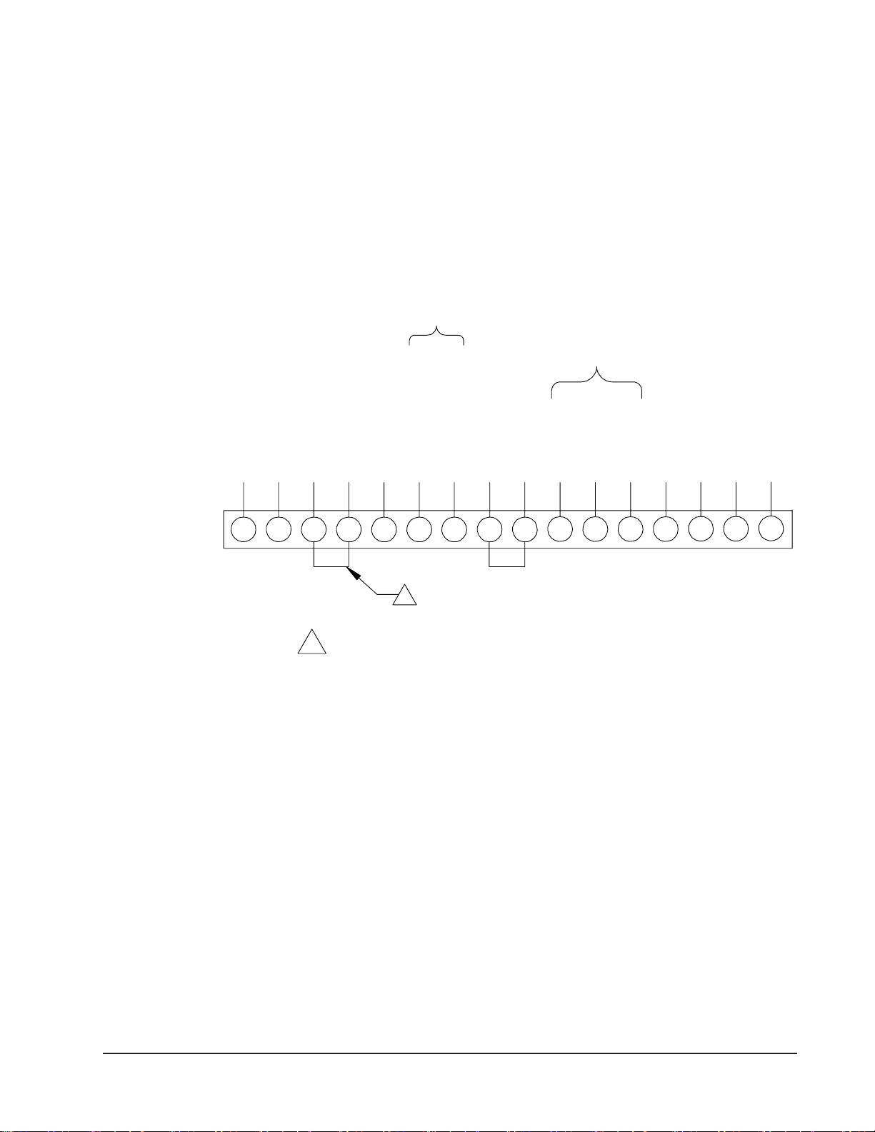
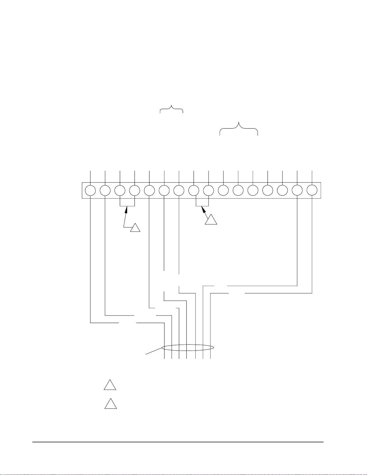
FIGURE 8
BASIC A/C with OPTIONAL ELECTRIC HEAT
NO ECONOMIZER
G
TERMINAL BLOCK A2
Y2 W1 E
3
RC Y Y1 1
W2
UNIT 24V F
OPEN OR SPECIAL USE AS REQUIRED
24V COMMON (GROUNDED)
ECONOMIZER STAGE 2
COMMON
ELECTRIC HEAT STAGE 2
ECONOMIZER STAGE 1
VENTILATION (IF EQUIPPED)
N.O. CONTACT
COMPRESSOR
OPEN OR SPECIAL USE AS REQUIRED
24V HOT
FAN (BLOWER)
ALARM RELAY
N.C. CONTACT
ELECTRIC HEAT STAGE 1
"J" MODULE
REFRIGERANT
IF EQUIPPED
1 FACTORY INSTALLED JUMPER FOR IMMEDIATE EMERGENCY SHUTDOWN
OF ALLHVAC OPERATIONS, REMOVE JUMPER AND CONNECT NORMALLY
CLOSED (NC) CONTACT TO R AND RT TERMINALS.
1
24V TRANSFORMER OUTPUT
DEHUMIDIFICATION (IF EQUIPPED)
D
Rt
MIS-2975 A
Manual 2100-588A
Page 16 of 29
FIGURE 9
BASIC A/C with OPTIONAL ELECTRIC HEAT
OLDER EIFM STYLE ECONOMIZER
A
12
CW1G
WIRING HARNESS
TERMINAL BLOCK Y1
EIFM ECONOMIZER
3E
UNIT 24V F
Y2 W2R Y
FACTORY INSTALLED JUMPER FOR IMMEDIATE EMERGENCY SHUTDOWN
OF ALLHVAC OPERATIONS, REMOVE JUMPER AND CONNECT NORMALLY
CLOSED (NC) CONTACT TO R AND RT TERMINALS.
OPEN OR SPECIAL USE AS REQUIRED
N.C. CONTACT
COMPRESSOR
ECONOMIZER STAGE 1
BLUE
COMMON
BLACK
ALARM RELAY
ELECTRIC HEAT STAGE 1
ORANGE
FACTORY INSTALLED JUMPER. REMOVE FOR 2-STAGE OPERATION
FAN (BLOWER)
VENTILATION INPUT (IF EQUIPPED)
N.O. CONTACT
BLACK
ON UNITS WITH 15OR MORE KW.
24V TRANSFORMER OUTPUT
IF EQUIPPED
PINK
OPEN OR SPECIAL USE AS REQUIRED
24V HOT
ELECTRIC HEAT STAGE 2
YELLOW
PURPLE
24V COMMON (GROUNDED)
ECONOMIZER STAGE 2
1
1
"J" MODULE
REFRIGERANT
DEHUMIDIFICATION (IF EQUIPPED)
Rt D
2
2
MIS-2980 A

Manual 2100-588A
Page 17 of 29
FIGURE 10
BASIC A/C with OPTIONAL ELECTRIC HEAT
NEWER ECONWM* STYLE ECONOMIZER
Y
FACTORY INSTALLED JUMPER FOR IMMEDIATE EMERGENCY SHUTDOWN
G
OF ALLHVAC OPERATIONS, REMOVE JUMPER AND CONNECT NORMALLY
WIRING HARNESS
2 E
3A
W1Y2CD
1
Y1
TERMINAL BLOCK R
MIS-2976 A
ECONWMT ECONOMIZER
W2
UNIT 24V
CLOSED (NC) CONTACT TO R AND RT TERMINALS.
F
3
3
VENTILATION INPUT (USED IF MINIMUM
YELLOW/RED
2
1
POSITION REQUIRED FOR VENTILATION)
BLACK
PINK
BROWN/WHITE
ORANGE
24V TRANSFORMER OUTPUT
YELLOW
FACTORY INSTALLED JUMPER. REMOVE FOR 2-STAGE OPERATION
RED
PURPLE
BLUE
24V COMMON (GROUNDED)
FAN (BLOWER)
24V HOT
COMPRESSOR
ECONOMIZER STAGE 2
ELECTRIC HEAT STAGE 2
N.C. CONTACT
N.O. CONTACT
COMMON
OPEN OR SPECIAL USE AS REQUIRED
OPEN OR SPECIAL USE AS REQUIRED
ON UNITS WITH 15OR MORE KW.
MUST BE ENERGIZED TO ENABLE MINIMUM POSITION.
ALARM RELAY
ECONOMIZER STAGE 1
REFRIGERANT
IF EQUIPPED
ELECTRIC HEAT STAGE 1
1
"J" MODULE
2
DEHUMIDIFICATION (IF EQUIPPED)
Rt
Manual 2100-588A
Page 18 of 29
START UP
THESE UNITS REQUIRE R-410A
REFRIGERANTAND POLYOL
ESTER OIL.
GENERAL:
1. Use separate service equipment to avoid cross
contamination of oil and refrigerants.
2. Use recovery equipment rated for R-410A
refrigerant.
3. UsemanifoldgaugesratedforR-410A(800psi/250
psi low).
4. R-410A is a binary blend of HFC-32 and HFC-125.
5. R-410A is nearly azeotropic - similar to R-22 and
R-12. Although nearly azeotropic, charge with
liquid refrigerant.
6. R-410A operates at 40-70% higher pressure than
R-22, and systems designed for R-22 cannot
withstand this higher pressure.
7. R-410A has an ozone depletion potential of zero,
but must be reclaimed due to its global warming
potential.
8. R-410A compressors use polyolester oil.
9. Polyol Ester oil is hygroscopic; it will rapidly
absorb moisture and strongly hold this moisture in
the oil.
10. A liquid line dryer must be used - even a deep
vacuum will not separate moisture from the oil.
11. Limit atmospheric exposure to 15 minutes.
12. If compressor removal is necessary, always plug
compressor immediately after removal. Purge with
small amount of nitrogen when inserting plugs.
TOPPING OFF SYSTEM CHARGE
If a leak has occurred in the system, the Manufacturer
recommends reclaiming, evacuating (see criteria
above), and charging to the nameplate charge. If done
correctly, topping off the system charge can be done
without problems.
With R-410A, there are no signicant changes in the
refrigerant composition during multiple leaks and
recharges. R-410A refrigerant is close to being an
azeotropic blend (it behaves like a pure compound
or single component refrigerant). The remaining
refrigerant charge, in the system, may be used after
leaks have occurred and then “top-off” the charge by
utilizing the pressure charts on the inner control panel
cover as a guideline.
REMEMBER: When adding R-410A refrigerant,
it must come out of the charging cylinder/tank as a
liquid to avoid any fractionation, and to ensure optimal
system performance. Refer to instructions for the
cylinder that is being utilized for proper method of
liquid extraction.
SAFETY PRACTICES:
1. Never mix R-410A with other refrigerants.
2. Useglovesandsafetyglasses,PolyolEsteroilscan
be irritating to the skin, and liquid refrigerant will
freeze the skin.
3. Never use air and R-410A to leak check; the
mixture may become ammable.
4. Do not inhale R-410A – the vapor attacks the
nervous system, creating dizziness, loss of
coordination and slurred speech. Cardiac
irregularities, unconsciousness and ultimate death
can result from breathing this concentration.
5. Do not burn R-410A. This decomposition
produces hazardous vapors. Evacuate the area if
exposed.
6. Use only cylinders rated DOT4BA/4BW 400.
7. Never ll cylinders over 80% of total capacity.
8. Store cylinders in a cool area, out of direct
sunlight.
9. Never heat cylinders above 125°F.
10. Never trap liquid R-410A in manifold sets, gauge
lines or cylinders. R-410A expands signicantly
at warmer temperatures. Once a cylinder or line is
full of liquid, any further rise in temperature will
cause it to burst.
WARNING
Failure to conform to these practices
could lead to damage, injury or death.

Manual 2100-588A
Page 19 of 29
START UP (Continued)
IMPORTANT INSTALLER NOTE
For improved start up performance wash the indoor coil
with a dish washing detergent.
HIGH PRESSURE SWITCH
All J**A/J**L wall mounted air conditioner series
models are supplied with a remote reset for the high and
low pressure switch. If tripped, this pressure switch may
be reset by turning the thermostat off then back on again.
THREE PHASE SCROLL COMPRESSOR
START UP INFORMATION
Scroll compressors, like several other types of
compressors, will only compress in one rotational
direction. Direction of rotation is not an issue with
single phase compressors since they will always start
and run in the proper direction.
However, three phase compressors will rotate in
either direction depending upon phasing of the power.
Since there is a 50-50 chance of connecting power
in such a way as to cause rotation in the reverse
direction, verication of proper rotation must be made.
Verication of proper rotation direction is made by
observing that suction pressure drops and discharge
pressure rises when the compressor is energized.
Reverse rotation also results in an elevated sound level
over that with correct rotation, as well as substantially
reduced current draw compared to tabulated values.
Verication of proper rotation must be made at the
time the equipment is put into service. If improper
rotation is corrected at this time, there will be no
negative impact on the durability of the compressor.
However, reverse operation for over one hour may have
a negative impact on the bearing due to oil pump out.
NOTE: If compressor is allowed to run in reverse
rotation for an extended period of time, the
compressor’s internal protector will trip.
All three phase compressors are wired identically
internally. As a result, once the correct phasing
is determined for a specic system or installation,
connecting properly phased power leads to the same
Fusite terminal should maintain proper rotation
direction.
The direction of rotation of the compressor may be
changed by reversing any two line connections to the
unit.
PHASE MONITOR
All units with three phase scroll compressors are
equipped with a 3 phase line monitor to prevent
compressor damage due to phase reversal.
The phase monitor in this unit is equipped with two
LEDs. If the Y signal is present at the phase monitor
and phases are correct the green LED will light.
If phases are reversed, the red fault LED will be lit and
compressor operation is inhibited.
If a fault condition occurs, reverse two of the supply
leads to the unit. Do not reverse any of the unit
factory wires as damage may occur.
CONDENSER FAN OPERATION
NOTE: Certain models may be equipped with a low
ambient control (LAC), and if so equipped, the
condenser fan motor will have delayed start
until system refrigerant operating pressure
builds up. After starting, the fan motor may
or may not cycle depending upon ambient
conditions. This is normal operation.
Applies to J42, J48, J60 and J70 models only. The
condenser fan motor on 230/208 volt, one and three
phase, 60 HZ units is a two-speed motor that comes
factory wired on high speed for peak performance. If
ambient conditions permit, it can be reconnected to
low speed (red wire) for lower sound level. See wiring
diagram.
50 HZ models must have fan wired on low speed.
These models are factory wired on low speed.
SERVICE HINTS
1. Caution owner/operator to maintain clean air
lters at all times. Also, not to needlessly close off
supply and return air registers. This reduces airow
through the system, which shortens equipment
service life as well as increasing operating costs.
2. Check all power fuses or circuit breakers to be sure
they are the correct rating.
3. Periodic cleaning of the outdoor coil to permit full
and unrestricted airow circulation is essential.

Manual 2100-588A
Page 20 of 29
SEQUENCE OF OPERATION
COOLING – Circuit R-Y makes at thermostat pulling
in compressor contactor, starting the compressor and
outdoor motor. (See NOTE under Condenser Fan
Operation if equipped with Low Ambient Control.) The
G (indoor motor) circuit is automatically completed
by the thermostat on any call for cooling operation or
can be energized by manual fan switch on subbase for
constant air circulation. On a call for heating, circuit
R-W1 make at the thermostat pulling in heat contactor
for the strip heat and blower operation. On a call for
second stage heat, R-W2 makes bringing on second heat
contactor, if so equipped.
COMPRESSOR CONTROL MODULE
The compressor control module is standard on all
models covered by this manual. The compressor
control module is an anti-short cycle/lockout timer with
high and low pressure switch monitoring and alarm
relay output.
Adjustable Delay On Make And Break Timer
On initial power up or anytime power is interrupted to
the unit, the delay on make period begins, which will
be 2 minutes plus 10% of the delay on break setting.
When the delay on make is complete and the high
pressure switch and low pressure switch is closed, the
compressor contactor is energized. Upon shutdown, the
delay on break timer starts and prevents restart until the
delay on break and delay on make periods have expired.
During routine operation of the unit with no power
interruptions, the compressor will operate on demand
with no delay.
High Pressure Switch and Lockout Sequence
If the high pressure switch opens, the compressor
contactor will de-energize immediately. The lockout
timer will go into a soft lockout and stay in soft lockout
until the high pressure switch closes and the delay on
break time has expired. If the high pressure switch
opens again in this same operating cycle, the unit will
go into manual lockout condition and the alarm relay
circuit will energize. Recycling the wall thermostat
resets the manual lockout.
Low Pressure Switch, Bypass, and Lockout
Sequence
If the low pressure switch opens for more than 120
seconds, the compressor contactor will de-energize
and go into a soft lockout. Regardless the state of the
low pressure switch, the contactor will reenergize after
the delay on make time delay has expired. If the low
pressure switch remains open, or opens again for longer
than 120 seconds, the unit will go into manual lockout
condition and the alarm relay circuit will energize.
Recycling the wall thermostat resets the manual lockout.
Alarm Relay Output
Alarm terminal is output connection for applications
where alarm relay is employed. This terminal is
powered whenever the compressor is locked out due to
HPC or LPC sequences as described.
NOTE: Both high and low pressure switch controls are
inherently automatic reset devices. The high
pressure switch and low pressure switch cut
outandcutinsettingsarexedbyspecicair
conditioner unit model. The lockout features,
both soft and manual, are a function of the
Compressor Control Module.
ADJUSTMENTS
Adjustable Delay on Make and Delay on Break
Timer
The potentiometer is used to select Delay on Break time
from 30 seconds to 5 minutes. Delay on Make (DOM)
timing on power-up and after power interruptions is
equal to 2 minutes plus 10% of Delay on Break (DOB)
setting:
0.5 minute (30 seconds) DOB = 123 second DOM
1.0 minute (60 seconds) DOB = 126 second DOM
2.0 minute (120 seconds) DOB = 132 second DOM
3.0 minute (180 seconds) DOB = 138 second DOM
4.0 minute (240 seconds) DOB = 144 second DOM
5.0 minute (300 seconds) DOB = 150 second DOM
During routine operation of the unit with no power
interruptions the compressor will operate on demand
with no delay.
Typical Settings for Dual Unit Installation:
Unit 1: DOB set at 2 minutes, and DOM is 132 seconds
Unit 2: DOB set at 4 minutes, and DOM is 144 seconds
PRESSURE SERVICE PORTS
High and low pressure service ports are installed on
all units so that the system operating pressures can be
observed. A pressure table can be found later in the
manual covering all models. It is imperative to match
the correct pressure table to the unit by model number.
See Table 4.
This manual suits for next models
216
Table of contents
Other Solair Air Conditioner manuals


