Solar-Log 50 User manual
1
Manual V.4.2.0
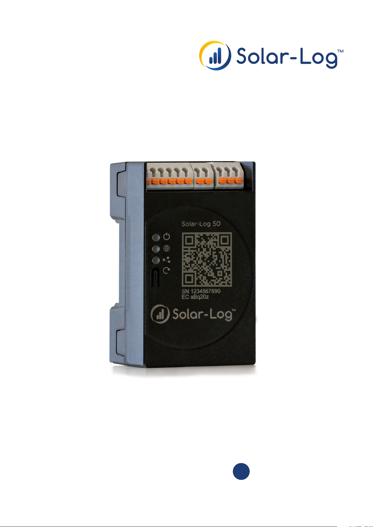
Solar-Log 50
EN

2
Publisher:
Solare Datensysteme GmbH
Fuhrmannstr. 9
72351 Geislingen-Binsdorf
Germany
International support
Tel.:+49 7428 9418 -640
Fax:+49 7428 9418 -280
e-mail: [email protected]
Italy
Technical support: +39 0471 631032
e-mail: [email protected]
France
Technical support: +33 97 7909708
e-mail: [email protected]
Switzerland
Technical support: +41 565 355346
e-mail: switzerland-[email protected]
United States
Technical support: +1 203 702 7189
e-mail: [email protected]

3
Table of Contents
1 Introduction.................................................................................................................... 7
2 Safety information ....................................................................................................... 8
2.1 Hazard Classes .............................................................................................................................................................. 8
3 Electric current.............................................................................................................. 9
4 Package Contents and Installation ...................................................................... 10
5 Solar-Log 50 Connections........................................................................................11
5.1 Top Connections Solar-Log 50.............................................................................................................................. 11
5.2 Bottom Connections Solar-Log 50 ..................................................................................................................... 12
6 Connector Assignments and Wiring....................................................................13
6.1 Notes on wiring the connections ......................................................................................................................... 13
6.2 2 x RS485 (A/B) or 1 x RS422............................................................................................................................... 14
7 Connecting the inverters..........................................................................................15
7.1 Switch o the inverters and the Solar-Log™. .................................................................................................. 16
8 Connecting accessories ............................................................................................17
8.1 External power meter............................................................................................................................................... 17
8.1.1 External power meters/accumulating meters.................................................................................................. 18
9 Other connections ......................................................................................................19
9.1 USB.................................................................................................................................................................................. 19

4
10 Installation.................................................................................................................... 20
10.1 Connect the Solar-Log™ to a network / PC.................................................................................................... 20
10.2 Initial set up of the Solar-Log 50 ......................................................................................................................... 21
11 Go to the Main Menu.................................................................................................22
11.1 Operating the Main Menu of the Solar-Log™ ................................................................................................. 25
11.1.1 Control elements ........................................................................................................................................................ 26
11.2 Explanations of the names in the main menu................................................................................................ 27
11.2.1 Header bar .................................................................................................................................................................... 27
11.2.2 Left-side navigation menu...................................................................................................................................... 27
11.2.3 Configuration Page.................................................................................................................................................... 27
11.2.4 Login Section Menu................................................................................................................................................... 28
11.2.5 Hide arrow.....................................................................................................................................................................30
11.2.6 New Firmware .............................................................................................................................................................30
11.3 Setting up of the Solar-Log™ with the configuration assistant.............................................................. 32
11.3.1 Solar-Log 50 Manual Configuration.................................................................................................................... 37
12 Main menu.....................................................................................................................38
12.1 Virtual LCD Display................................................................................................................................................... 38
13 Configuration Menu...................................................................................................39
13.1 Configuring network settings............................................................................................................................... 39
13.1.1 Ethernet .........................................................................................................................................................................40
13.1.2 Proxy ...............................................................................................................................................................................42
13.2 Internet Configuration............................................................................................................................................. 43
13.2.1 Portal...............................................................................................................................................................................43
13.3 Configuring connected devices........................................................................................................................... 45
13.3.1 Device definition.........................................................................................................................................................46
13.3.2 Device Detection........................................................................................................................................................48
13.3.3 Configuring devices ..................................................................................................................................................49
13.3.4 Configuring inverters................................................................................................................................................49
13.3.5 Generation Information on PAC Correction Factor ......................................................................................50
13.3.6 Configuring power meters....................................................................................................................................... 51
13.3.7 Configure the battery............................................................................................................................................... 52
13.3.8 Module Fields, Power Output and Descriptions............................................................................................. 52
13.4 Feed-in management (with an active license)............................................................................................... 54
13.4.1 Plant parameters ........................................................................................................................................................54
13.4.2 Active power................................................................................................................................................................54
13.4.3 Active power deactivated....................................................................................................................................... 55
13.4.4 70% fixed reduction .................................................................................................................................................. 55
13.4.5 70% Fixed reduction with the calculation of self-consumption .............................................................. 56
13.4.6 Adjustable reduction ................................................................................................................................................ 56
13.4.7 Adjustable Reduction with the Calculation of Self-Consumption........................................................... 57
13.4.8 Fixed reduction in watts.......................................................................................................................................... 57
13.4.9 Fixed reduction in watts with the calculation of self-consumption ....................................................... 57

5
13.4.10 Percentage of consumption for an adjustable reduction.......................................................................... 58
13.5 Editing Data ............................................................................................................................................................... 58
13.5.1 System backup........................................................................................................................................................... 58
13.5.2 Backup ........................................................................................................................................................................... 61
13.5.3 Reset.............................................................................................................................................................................. 63
13.6 System Configuration............................................................................................................................................. 64
13.6.1 Access control............................................................................................................................................................64
13.6.2 HTTPS............................................................................................................................................................................ 65
13.6.3 Language/Country/Time .......................................................................................................................................66
13.6.4 Licenses ........................................................................................................................................................................68
13.6.5 Firmware ......................................................................................................................................................................69
14 Diagnostics Menu......................................................................................................72
14.1 Accessing Support .................................................................................................................................................. 72
14.2 Starting Feed-in management (with an active license)............................................................................ 73
14.2.1 Explanation of the Values in the Power Reduction Section..................................................................... 74
14.2.2 Explanation of the Symbols in the Feed-in power (% DC) column:...................................................... 76
15 Yield Data Menu..........................................................................................................77
15.1 Current values ............................................................................................................................................................ 77
15.1.1 Table................................................................................................................................................................................ 78
16 Symbols on the virtual LCD display ....................................................................79
16.1 Meaning of the symbols on the virtual LCD display .................................................................................... 79
16.2 Fault messages .......................................................................................................................................................... 80
16.3 Normal operation ...................................................................................................................................................... 80
17 Notifications via LED .................................................................................................81
17.1 LED status indications.............................................................................................................................................. 81
18 Faults...............................................................................................................................82
18.1 Restarting and resetting......................................................................................................................................... 82
18.1.1 Reset buttons .............................................................................................................................................................. 82
18.2 Fault messages .......................................................................................................................................................... 83
18.2.1 Fault messages time ................................................................................................................................................. 83
18.2.2 Fault messages Internet .......................................................................................................................................... 83
18.2.3 Portal Transfer Fault messages.............................................................................................................................84
19 Cleaning and care.......................................................................................................85

6
19.1 Cleaning tips .................................................................................................................................................................. 85
19.2 Care tips........................................................................................................................................................................... 85
20 Disposal...........................................................................................................................86
21 Appendix .........................................................................................................................87
21.1 Internet ports................................................................................................................................................................. 87
22 Dimensions ....................................................................................................................88
23 List of Figures................................................................................................................89

7
Introduction
1 Introduction
This manual is intended for use by solar energy technicians and professional electricians, as well as So-
lar-Log 50 users. It should be noted that the installation and commissioning of the individual components
is only to be performed by properly trained specialists. Refer to Chapter 4 "Safety information" for more
information.
The wiring for the devices is described in detail in the Component Installation Manual.
The Solar-Log™ must only be used by persons who have fully read and understood the manual before
installing, operating and/or servicing the device.
Our product documentation is being constantly updated and expanded.
The current versions of the documents can be downloaded from our website:
https://www.solar-log.com/de/support/downloads.
The descriptions in this manual refer to firmware version 4.2.0.

8
Safety information
2 Safety information
In order to protect people, the device itself, and other equipment, please pay attention to the following
before handling the product:
• the content of this manual,
• the safety information,
• the warning signs and type plates attached to the product.
Note:
All the actions described in this manual for wiring and working on the individual components must be
carried out only by specially trained electricians. All repairs should only be carried out by similarly trained
personnel, or by the manufacturers themselves.
Solare-Datensysteme GmbH is not liable for any personal injuries, property damages and system malfunc-
tions and their consequences which result from not adhering to the product documentation.
2.1 Hazard Classes
The safety instructions in this document are represented with standard signs and symbols. Two classes of
risk are identified, depending on their probability of occurrence and the seriousness of their consequences.
Danger
Indicates an imminently hazardous situation to life
Non-compliance with this warning can lead to severe and irreversible injuries or death
Caution
Indicates an imminently hazardous situation to people, or a risk of material damage
Non-compliance with this warning can lead to irreversible injuries or to material dam-
age.
9
Electric current
3 Electric current
Danger
Risk of death by electric shock if inverters are opened.
Never open the inverter housing when the inverter is connected to power.
Refer to Switching inverters off.
Always read the installation and safety instructions given in the manual for the corre-
sponding inverter.
Danger
Danger of death if there is condensation in the power supply unit when started!
Condensation can occur if the power supply unit is moved directly from a cold environ-
ment to a warm environment.
Wait until the temperatures have equalized before doing this.
Caution
Damage to the electrical components in inverters and on interface cards due to electro-
static discharge.
Avoid contact with component connections and plug contacts.
Before picking up the component, ground yourself by holding the protective conductor
(PE) or the unpainted part of the inverter housing.
Caution
Damage to the electrical components of the Solar-Log™ due to the wiring of the So-
lar-Log™!
Disconnect the Solar-Log™ from the power supply.
Caution
Risk of electric shock.
Do not use the unit if the housing of the external power supply unit is damaged. A
damaged power supply unit must be replaced by one of the same type in order to
avoid danger.
Caution
The Solar-Log™ may only be used indoors or enclosed spaces.
The device has the protection class IP20.
10
Package Contents and Installation
4 Package Contents and Installation
Check the package contents before proceeding to assembly and installation.
Report any damage or missing parts to the forwarding agent and dealer immediately.
The device is produced according to protection class IP20 and is intended only for installation in interior
areas that are dry and dust-free.
It can mounted on the wall (see illustration below) or on a top-hat rail (refer to the Solar-Log™ dimensions
in chapter 22). Power can come from a DIN rail power supply or a 24V power supply with an adapter.
Note
Please note that a power supply is not included in the package contents.
Note
We recommend using the Solar-Log™ power supply (Art.N.: 256226)
Please note that: GND 24V
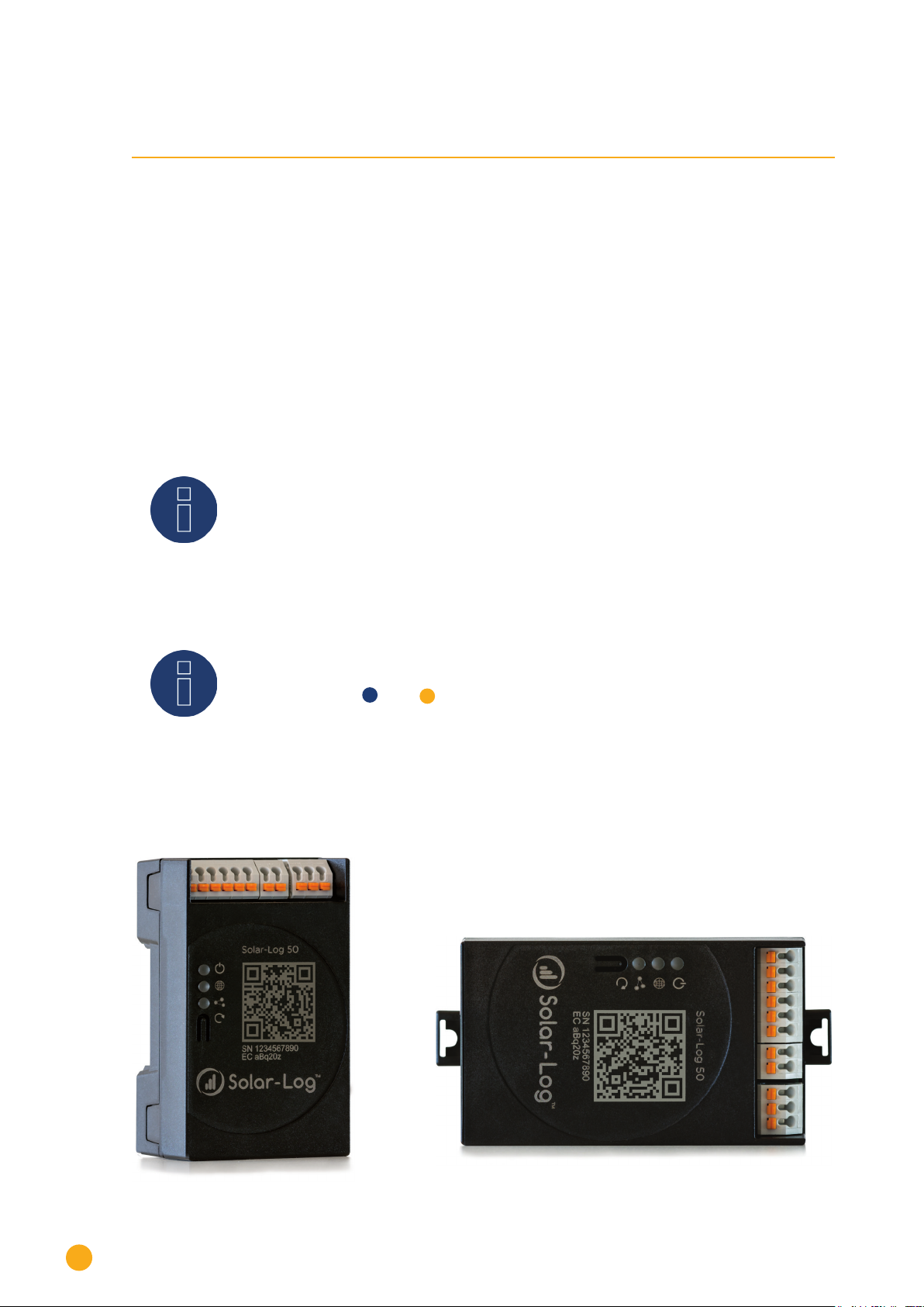
Wall mounting
For wall mounting, extend the snap-fit tabs on the bottom of the device and attach it to the wall with a
suitable device and accessories.
Fig.: Solar-Log 50 without extended snap-t tabs Fig.: Solar-Log 50 with extended snap-t tabs
11
Solar-Log 50 Connections
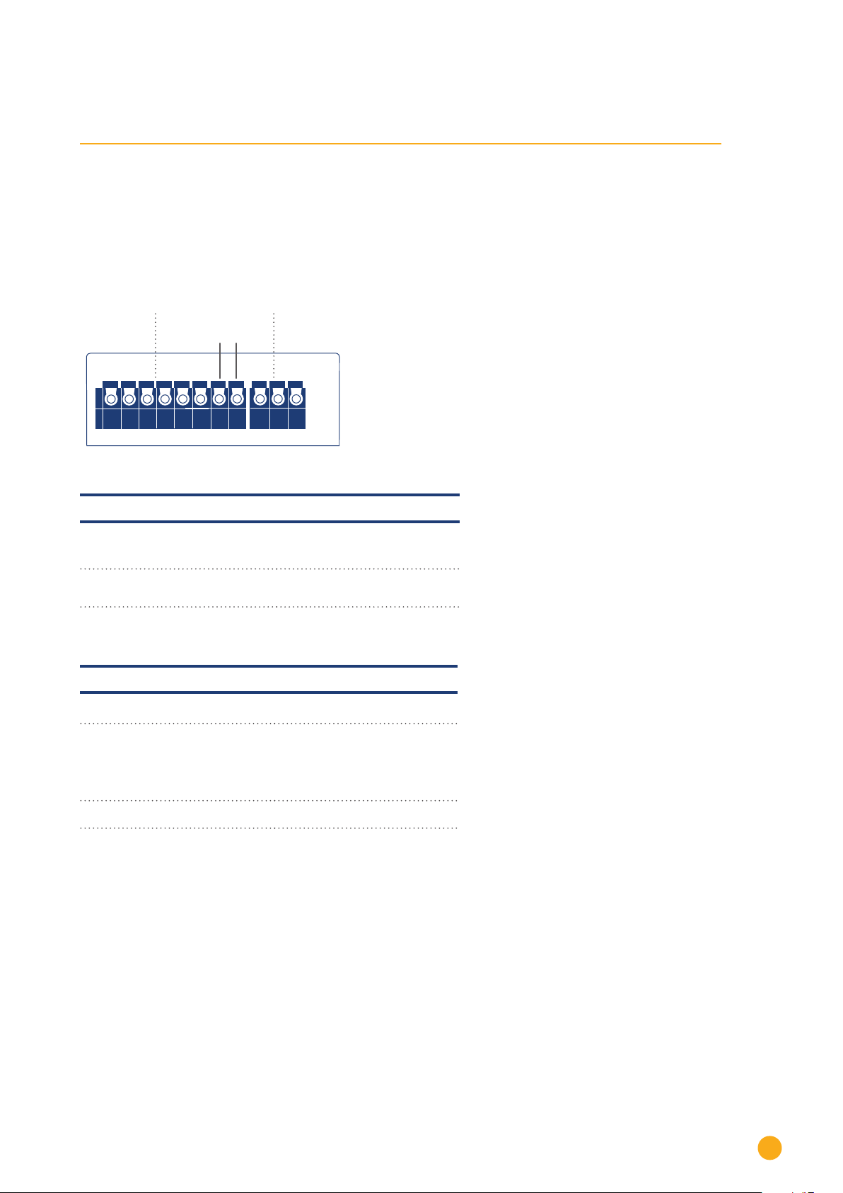
5 Solar-Log 50 Connections
5.1 Top Connections Solar-Log 50
Input: 24 V/ 1A DC2x RS485 or RS422
Pins without
function
US BEthernet
6 5 4 3 2 1-+
Fig.: Top Connections – Solar-Log 50
Solar-Log 50 Top connections
2 x RS485
or RS422
Connection for inverters and
additional accessories
Input:
24 V/1A DC
Connection pins for the power
supply
Technical Data
Nominal voltage 24V = +- 5% or 24VDC +- 5%
Maximum cable cross-section SOLID WIRE: 30-16 AWG /
0.05-1.31 mm2(Solid wire)
STRANDED WIRE: 30-16 AWG
/ 0.05-1.31 mm2(Litz wire)
Power consumption < 0.5W

12
Solar-Log 50 Connections
5.2 Bottom Connections Solar-Log 50
Input: 24 V/ 1A DC
2x RS485 oder RS422 USBEthernet
1 2 3 4 5 6-+
Fig.: Bottom connections Solar-Log 50
Bottom of the Solar-Log 50
USB USB connection. Suitable
for USB sticks.
Not suitable for a connec-
tion to a PC / laptop.
Network Ethernet network interface,
10/100 Mbit
Note
This USB connection can only be used for USB sticks and not for a direct PC or laptop connec-
tion.

13
Connector Assignments and Wiring
5.2 Bottom Connections Solar-Log 50
Input: 24 V/ 1A DC
2x RS485 oder RS422 USBEthernet
1 2 3 4 5 6-+
Fig.: Bottom connections Solar-Log 50
Bottom of the Solar-Log 50
USB USB connection. Suitable
for USB sticks.
Not suitable for a connec-
tion to a PC / laptop.
Network Ethernet network interface,
10/100 Mbit
Note
This USB connection can only be used for USB sticks and not for a direct PC or laptop connec-
tion.
6 Connector Assignments and Wiring
The following connecting cables, which may be needed for various purposes, are not included in the pack-
age content.
• To connect a router, you need a network cable with the appropriate length. If you want to connect the
Solar-Log™ directly to your PC or laptop, you need to use a crossover cable.
• Cable to connect the Solar-Log™ to an inverter.
• Sets of prefabricated cables are available as accessories suitable for the inverter concerned. The
length of these cable sets is 3 m.
• If you want to connect several inverters to Solar-Log™, you need suitable cables and connectors to
connect the inverters to each other.
• When wiring with CAT cables, the twisted pair of wires should be used.
6.1 Notes on wiring the connections
The wiring of the inverters and accessories needs to be carried out with the greatest care and attention.
The most frequent source of errors when installing the Solar-Log™ is faulty wiring.
For this reason, we recommend:
• Wiring with high quality cables
For example: LIYCY >=0.14mm2or Cat 5/7 SSTP
• Refer to the manufacturer's specifications in regard to UV resistance and mounting type when wiring
in outside areas.
• A larger cable diameter is recommended for longer distances.
• Use ferrules with flexible wires
• Twist the corresponding wire pairs and shielding
• Wire from left-to-right.
• Wire from light to dark.

14
Connector Assignments and Wiring
6.2 2 x RS485 (A/B) or 1 x RS422
Use the provided terminal blocks when connecting inverters or accessories to the RS485 or RS422 inter-
face.
RS485 Connection Block Pin Assignment
RS485-A RS485-B
PIN Assignment Assignment
1 Data+ -
2 12 V -
3 Ground / GND -
4 Data- -
5 - Data+
6 - Data-
RS422 Connection Block Pin Assignment
RS422
PIN Assignment
1 T/RX+
2 12V
3 Ground / GND
4 T/RX-
5 R/TX+
6 R/TX-
Note
If inverters that use the RS422 connection are connected to this interface (e.g. Fronius,
AEG, Riello), then it is not possible to connect accessories such as sensors or meters to
this bus.

15
Connecting the inverters
7 Connecting the inverters
As each inverter manufacturer uses different wiring connections and connectors, the corresponding data
cables must be adapted correctly.
• See Chapter„Belegung und Verkabelung der Anschlüsse“ for terminal block connector wiring diagrams
for the connection to the Solar-Log™
• Please refer to the Component Connection Manual when connecting inverters supported by the So-
lar-Log™. (Download from https://www.solar-log.com/en/support/downloads/manuals)
Note
Solare Datensysteme GmbH supplies suitable connection cables for most inverter manu-
facturers.
Always read the manufacturer-specific instructions for connecting the data cable. You will find these in-
structions in the manufacturer's documentation.
However, when assigning the inverter wiring on the Solar-Log™, follow the instructions in this manual, oth-
erwise the inverters will not be detected by Solar-Log™.
Danger
Risk of death by electric shock if inverters are opened.
Never open the inverter housing when the inverter is connected to power.
See the chapter "Switching inverters off."
Always read the installation and safety instructions given in the manual for the corre-
sponding inverter.

16
Connecting the inverters
7.1 Switch o the inverters and the Solar-Log™.
Switching inverters off
Before a making a cable connection between the Solar-Log™ and the connections inside the inverter and
before installing an interface card in the inverter, always turn off all of the inverters first.
To do this, read the manufacturer's documentation for the inverter, and proceed as follows:
• Disconnect the AC side.
• Disconnect the DC side.
• Wait at least 5 minutes until the condensers in the inverters have discharged.
Turn the Solar-Log™ off.
• Hold down reset button for 10 seconds and then release it as soon as the components LED turns ( )
Orange. The Solar-Log™ will shut down and can be disconnected from the power supply (see chapter
18.1.1 "Reset Button" for more information).

17
Connecting accessories
8 Connecting accessories
8.1 External power meter
External power meters can be connected to the Solar-Log™ via the RS-485 bus.
The energy recorded by these meters can be used for numerous applications:
• Generator Mode:
This mode is used, for example, for inverters that are not directly supported by Solar-Log™.
• Total yield meter:
This mode is used to record the energy production of several inverters.
• Consumption meter:
This mode is used to measure power consumption and to make it possible to display this data.
Note
We recommend using the meters that we have tested and offer.
We cannot guarantee the functionality of other products.
Note
Refer to the Meter Connection Manual for all of the supported meters and their wiring
diagram. Download it from our website:
https://www.solar-log.com/en/support/downloads/manuals

18
Connecting accessories
8.1.1 External power meters/accumulating meters
With multiple phase meters, a basic distinction is made between phase-exact and accumulating meters.
Accumulating meters provide the total values from all three phases. The meter calculates the total output
(also to and from the grid) of the individual phases and provides this total as a single value.
In the example:
Phase 1 supplies 3 kW via an inverter (single phase).
Phase 2 draws 2 kW (energy)
Phase 3 draws 1 kW (energy)
With an accumulating meter, this results in a total of 0 kW.
Examples of accumulating meters are the Janitza UMG 104/UMG 604 and the Solar-Log™ Pro380-Mod.

19
Other connections
9 Other connections
9.1 USB
The Solar-Log 50 comes with an USB connection. This USB connection can only be used for USB sticks and
not, for example, for a direct PC or laptop connection.
Note
When a USB stick is connected, the Solar-Log™ automatically saves a backup in the
backup folder. A maximum of 10 backup files are saved in the directory. Older backup
files are automatically deleted.
The backup is saved on the USB stick in the directory /Backup with the following file names:
• solarlog_backup_YYMMDD.dat:
YYMMDD = year, month and day - each two digits, e.g.
180807 is then 07 August 2018

20
Installation
10 Installation
The Solar-Log 50 has an integrated web server, which contains all the software necessary for operation
and configuration.
No additional software needs to be installed on the PC to access the Solar-Log™.
A common web browser with JavaScript enabled is required.
We recommend using the current version of Mozilla's Firefox, Google's Chrome or Microsoft's Edge.
To run the web browser, a network connection is required between the PC or laptop and Solar-Log™, and
Solar-Log™ must be up and running.
It is required to have DHCP enabled on the router.
10.1 Connect the Solar-Log™ to a network / PC.
The Solar-Log™ is equipped with a standard Ethernet RJ45 socket, which can be connected through any
commercially available network cable. Speeds of 10 Mbit and 100 Mbit are supported.
In general, any PC networking technology can be used for connecting the Solar-Log™. The following tech-
nologies are available:
• Connection through an Internet router:
Ethernet RJ45 network cable.
• Direct cable connection from the PC to the Solar-Log™:
Ethernet RJ45 network patch cable.
If the Solar-Log™ is operated via a router, ensure that the necessary ports have been activated (see Chap-
ter „Internet-Ports“).
Note
The Solar-Log 50 has DHCP activated by default to be able to establish a connection
when connected to a router with DHCP enabled.
Other manuals for 50
1
Table of contents
Other Solar-Log Gateway manuals


