Sintrones NBOX-5040 User manual

NBOX-5040
Network Computing
User's Manual
Version 1.0

SINTRONES® Technology Corp.
User Manual
Copyright
©2009 by SINTRONES® Technology Corp. All Rights Reserved.
No part of this publication may be reproduced, transcribed, stored in a retrieval sys-
tem, translated into any language, or transmitted in any form or by any means such as
electronic, mechanical, magnetic, optical, chemical, photocopy, manual, or otherwise,
without prior written permission from SINTRONES® Technology Corp.
Other brands and product names used herein are for identication purposes only and
may be trademarks of their respective owners.
Disclaimer
SINTRONES® Technology Corp. shall not be liable for any incidental or consequential
damages resulting from the performance or use of this product.
SINTRONES® Technology Corp. makes no representation or warranty regarding the
content of this manual. Information in this manual had been carefully checked for
accuracy;however, no guarantee is given as to the correctness of the contents. For
continuing product improvement, SINTRONES® Technology Corp. reserves the right
to revise the manual or make changes to the specications of this product at any time
without notice and obligation to any person or entity regarding such change. The infor-
mation contained in this manual is provided for general use by customers.
This device complies to Part 15 of the FCC Rules. Operation is subject to the follow-
ing two conditions:
1. This device may not cause harmful interference.
2. This device must withstand any background interference including those that may
cause undesired operation.

CAUTION
Incorrectly replacing the battery may damage this computer. Replace only with
the same or its equivalent as recommended by SINTRONES®Technology
Corp. Dispose used battery according to the manufacturer's instructions.
Safety Information
Read the following precautions before setting up a SINTRONES Product.
Electrical safety
•
To prevent electrical shock hazard, disconnect the power cable from the electrical
outlet before relocating the system.
•
When adding or removing devices to or from the system, ensure that the power
cables for the devices are unplugged before the signal cables are connected.
If possible, disconnect all power cables from the existing system before you add a
device.
•
Before connecting or removing signal cables from the motherboard, ensure that all
power cables are unplugged.
•
Seek professional assistance before using an adapter or extension cord.
These devices could interrupt the grounding circuit.
•
Make sure that your power supply is set to the correct voltage in your area.
If you are not sure about the voltage of the electrical outlet you are using, contact
your local power company.
•
If the power supply is broken, do not try to x it by yourself. Contact a qualied
service technician or your retailer.
Operation safety
•
Before installing the motherboard and adding devices on it, carefully read all the
manuals that came with the package.
•
Before using the product, make sure all cables are correctly connected and the
power cables are not damaged. If you detect any damage, contact your dealer
immediately.
•
To avoid short circuits, keep paper clips, screws, and staples away from connectors,
slots, sockets and circuitry.
•
Avoid dust, humidity, and temperature extremes. Do not place the product in any
area where it may become wet.
•
Place the product on a stable surface.
•
If you encounter technical problems with the product, contact a qualied service
technician or your retailer.

TABLE OF CONTENTS
1 Function Introduction
1.1 Model Specications ......................................................................................6
1.2 NBOX-5040 Illustration <Mainboard> ............................................................8
1.3 Memory Module Installation ...........................................................................9
1.4 Connectors & Jumpers Guide
Jumper List...........................................................................................10
Connector List ......................................................................................10
Rear Panel Connector List ...................................................................11
Jumper Setting ..................................................................................... 11
Connector Pin Assignment...................................................................14
2 System Installation
2.1 System Introduction .....................................................................................18
2.2 Opening Chassis..........................................................................................21
2.3 Memory Module Installation .........................................................................22
2.4 CompactFlash Card Installation ...................................................................24
2.5 HDD Installation ...........................................................................................25
3 BIOS
3.1 Entering The BIOS .......................................................................................26
3.2 Main..............................................................................................................27
3.3 Advanced .....................................................................................................28
3.4 Boot..............................................................................................................31
3.5 Chipset .........................................................................................................32
3.6 Power ...........................................................................................................33
3.7 Security ........................................................................................................34
3.8 Exit ..............................................................................................................35

5
English
1 Function Introduction
Overview
The NBOX-5040 is a compact fanless box and low power consumption Network se-
curity platform which was customized design to be served as a security gateway, for
instance, anti-virus, anti-spy, IDS/IPS, VPN and UTM applications. This embedded
hardware platform is based on a 5.25” industrial SBC with Intel® Atom™ Processor
N270 (512K Cache, 1.60 GHz, 533 MHz FSB), 945GSE/ICH7M chipset, and DDR2 533
SO-DIMM up to 2GB. Featured are a 2.5” SATA hard drive bay, CompactFlash Type II
slot, Four GbE, One Mini-PCI Express socket, Two LED indicators, One Factory Default
switch button.
Take out the NBOX-5040 from the carton box, check if the unit is properly secure
in the plastic bag.
Check the contents of the carton box:
1 x NBOX-5040
1 x Drivers / Manual CD
1 x Console cable
1 x Power Adapter
1 x Power Cord (optional)
1 x 2.5" HDD kit (optional)
Fanless design and low power consumption
Compact size
4 x GbE
1 x Mini-PCI Express socket
Cost effective Network platform solution
Flexible Software Control Bypass
Friendly LED indicators (Software status, Alarm)
1 x 2.5" SATA HDD, CF card
Check list
Feature

6
English
CPU • Intel Atom 1.6GHz Ultra Low Power CPU onboard
Cache • 512KB L2 Cache
Memory • 1 x DDR2 SO-DIMM Socket, 2GB per DIMM (Max 2GB)
• DDR2 533MHz supported
Chipsets • Intel 945GSE + ICH7M
Watchdog • 1 ~ 255 Level
Serial Port • 2 x Console Port
USB Port • 4 x USB 2.0 compliant (2 x Rear I/O with LAN)
LAN • 4 x Gigabit Ethernet (Intel 82574L), Optional Eth0 & 1 Bypass
• IEEE 802.3u 100Base-T specication compliant
• 10MB/s, 100MB/s, 1GB/s
• Support Wake-On-LAN function
Expansion • 1 x Mini-Card for Wireless 802.11b/g/n Module (Optional)
Graphics Chipset • Intel GMA 950 256bit 3D engine with a powerful 166MHz core and
DirectX 9 3D hardware accelerationt
Graphics VRAM • Dynamic Video Memory Technology(DVMT)3.0
• supports up to 224MB of Video memory
Storage Interface • 1 x 2.5" SATA HDD
• 1 x CF
1.1 Model Specifications

7
English
Front View
LED • Power LED
• Bypass LED
• Status LED
• Alarm LED
• Act/Link LED for LAN1~LAN4
• Speed LED for LED for LAN1~ LAN4
Rear View
LAN Port • 4 x Intel 82574L Gigabit LAN ports
COM Port • 1 x RJ45 Console
USB Port • 2 x USB 2.0 ports
Power • 12V DC Power Jack Input
Button • Switch button for Factory Default
Dimension • 219(W) x 40(H) x 151(D) mm
Construction • Aluminum
Operating Temp. • 0°C ~ 40°C, 5%-90%, non-condensing
Storage Temp. • -20°C ~ 70°C, 5%-90%, non-condensing

8
English
1.2 NBOX-5040 Illustration
Mainboard

9
English
1.3 Memory Module Installation
The NBOX5020 provide one 200pins SODIMM slot for DDR2 533/667MHz
SDRAM memory modules and supports memory sizes up to 2GB.
Step 1. Locate the SODIMM (DIMM1)
slot on the mainboard.
Step 2. Align the notch of the memory
module with that of the memory
slot.
Step 3. Gently insert the module into
the slot at a 45-degree angle.
Step 4. Push the memory down until it
snaps into the locking mechanism.
45-degree
angle
SODIMM slot- DIMM1
1
2
notch

10
English
1.4 Connectors & Jumpers Guide
Jumper List
Connector List
Location Function BIOS Result
JP1 AT/ATX Mode Selection
JP2 WDT Signal Selection
JP3 Clear CMOS Selection
JP4 LAN Bypass Signal Selection
JP5 LAN Bypass function Selection
Location Function BIOS Result
BAT1 CR2032 Battery Holder
CFD1 Compact Flash type I/II Connector
VGA1 VGA Box Header
CN1 LAN4 ACT# / STATUS LED
CN2 LAN3 ACT# / STATUS LED
CN3 LAN1 ACT# / STATUS LED
CN4 GPIO Status LED
CN5 Bypass Function Status LED
CN6 LAN2 ACT# / STATUS LED
CN12 User Dene
MPCIE1 Mini PCIE Connector
DIMM1 DDR2 Memory SO-DIMM Socket
USB1 USB Connector
USB2 USB Port-2&3 Pin Header
ATX1 4 pin 12V Power in Connector
FAN1 CPU FAN Connector
SATA1 Primary SATA Connector
SATA2 Secondary SATA Connector
FP1 Power LED Pin Header
FP2 Front Panel Pin Header
FP3 External LED Board Pin Header
CN7 Power Out Connector
CN8 Power Out Connector
CN10 LPC Debug Header

11
English
Rear Panel Connector List
Location Function BIOS Result
CN11 Extemal Adapter Power Input Connectior
LAN1 10/100/1000 Ethernet RJ-45 Connector
LAN2 10/100/1000 Ethernet RJ-45 Connector
LAN3 10/100/1000 Ethernet RJ-45 Connector
LAN4 10/100/1000 Ethernet RJ-45 Connector
COM1 RS232 of RJ-45 Connector
COM2 RS-232 Port-2 Box Header
Jumper Setting
• PowerModeSelection(JP1)
• WDTSignalSelection(JP2)
• ClearCMOSSelection(JP3)
Jumper Status
Open AT Mode
Short ATX Mode
Setting Status
1-2 Short WDT TO BYPASS
2-3 Short WDT TO SYSTEM
Setting Status
1-2 Open Normal Operation
1-2 Short Clear CMOS
Pitch:2.0mm[YIMTEX3291*02SAGR(6T)]
Pitch:2.0mm[YIMTEX3291*02SAGR(6T)]
Pitch:2.54mm[YIMTEX3321*02SAGR]

12
English
• Giga-bitEnternetRJ-45Connector(LAN1)
• RS-232Port-1RJ45Connector(COM1)
Pin Signal
1 DCD
2 DSR, Data set ready
3 RXD, Receive date
4 RTS, Request to send
5TXD, Transmit data
6 CTS, Clear to send
7 DTR, Data Terminal ready
8RI
Pin Signal
1MDI[0]+
2 MDI[0]-
3MDI[1]+
4 MDI[1]-
5MDI[2]+
6 MDI[2]-
7MDI[3]+
8 MDI[3]-
• LANBypassSignalSelection(JP4)
• LANBypassFunctionSelection(JP5)
Jumper Status
1-2 Short WDT
2-3 Short SIO GPIO
Setting Status
Open Bypass Disable
Short Bypass Enable
Pitch:2.0mm[YIMTEX3291*02SAGR(6T)]
Pitch:2.0mm[YIMTEX3291*02SAGR(6T)]

13
English
• Giga-bitEthernetRJ-45Connector(LAN2)
• Giga-bitEnternetRJ-45Connector(LAN3)
• Giga-bitEnternetRJ-45Connector(LAN4)
• USB1
Pin Signal
1MDI[0]+
2 MDI[0]-
3MDI[1]+
4 MDI[1]-
5MDI[2]+
6 MDI[2]-
7MDI[3]+
8 MDI[3]-
Pin Signal
1MDI[0]+
2 MDI[0]-
3MDI[1]+
4 MDI[1]-
5MDI[2]+
6 MDI[2]-
7MDI[3]+
8 MDI[3]-
Pin Signal Name Pin Signal Name
1+5VSB 5+5VSB
2 USB1- 6 USB0-
3USB1+ 7USB0+
4 GND 8 GND
Pin Signal
1MDI[0]+
2 MDI[0]-
3MDI[1]+
4 MDI[1]-
5MDI[2]+
6 MDI[2]-
7MDI[3]+
8 MDI[3]-
14
English
Connector Pin Assignment
• VGABOXHEADER(VGA1)
• CompactFlashtypeI/IIConnector(CFD1)
Pin Signal Pin Signal
1 VGA_R 2 VGA_G
3 VGA_B 4 N.C.
5 GND 6 GND
7 GND 8 GND
9+5V 10 GND
11 N.C. 12 VGA_SDATA
13 VGA_HS 14 VGA_VS
15 VGA_SCLK 16 GND
Pin Signal Pin Signal
1 GND 26 GND
2 SDD3 27 SDD11
3 SDD4 28 SDD12
4 SDD5 29 SDD13
5 SDD6 30 SDD14
6 SDD7 31 SDD15
7 SDCS#1 32 SDCS#3
8 GND 33 GND
9 GND 34 SDIOR#
10 GND 35 SDIOW#
11 GND 36 +5V
12 GND 37 IDEIRQ15
13 +5V 38 +5V
14 GND 39 PCSEL
15 GND 40 NC
16 GND 41 SIDERST#
17 GND 42 SIORDY
18 SDA2 43 NC
19 SDA1 44 SDDACK#
20 SDA0 45 IDEACT#
21 SDD0 46 S66DECT
22 SDD1 47 SDD8
23 SDD2 48 SDD9
24 IOIS16# 49 SDD10
25 GND 50 GND

15
English
• RS-232/422/485Wafer(COM2)
Pin Signal
1 DCD, Data carrier detect
2 DSR, Data set ready
3 RXD, Receive date
4 RTS, Request to send
5TXD, Transmit data
6 CTS, Clear to send
7 DTR, Data Terminal ready
8RI, Ring indicator
9GND, Ground
10 +5V
Pitch:1.25mm[YIMTEX501MW1*10STR]
• +5VPowerOutputConnector(CN8)
• +12V&+5VPowerOutputWafer(CN7)
• FrontPanel1PinHeader(FP1)
Pin Signal Name
1+5V
2 GND
Pin Signal Name
1+5V
2 GND
4+12V
Pin Signal Name Pin Signal Name
1Reset Button + 2Speaker +
3 Reset Button - 4 NC
5HDD LED + 6 NC
7 HDD LED - 8 Speaker -
Pitch:5.08mm[YIMTEX541FW4RTR]
Pitch:2.5mm[YIMTEX512CW4RTR]
Pitch:2.54mm[YIMTEX3322*04SAGR]

16
English
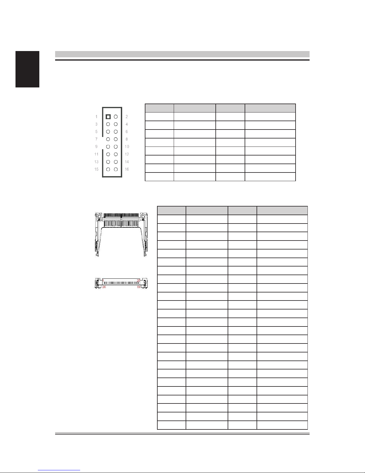
• FrontPanel2PinHeader(FP2)
• FrontPanel3PinHeader(FP3)
• DDR2MemorySO-DIMMSocket(DIMM1)
Pin Signal Name Pin Signal
1Power LED + 2Power Button +
3 NC 4 Power Button -
5 Power LED - 6 NC
7 Keyboard Lock 8 SMBus Data
9 GND 10 SMBus Clock
Pin Signal Name Pin Signal
1 LAN1_ACT 2 LAN1_ACT#
3 LAN1_1000# 4 LAN1_100#
5 LAN2_ACT 6 LAN2_ACT#
7 LAN2_1000# 8 LAN2_100#
9 LAN3_ACT 10 LAN3_ACT#
11 LAN3_1000# 12 LAN3_100#
13 LAN4_ACT 14 LAN4_ACT#
15 LAN4_1000# 16 LAN4_100#
17 HDD_ACT 18 HDD_ACT#
19 +5VSB 20 +SUSLED
21 +5VSB 22 +BYPASSLED
23 +5VSB 24 +AlarmLED
25 +5VSB 26 +STATUS
Pitch:2.54mm[YIMTEX3322*05SAGR]
Pitch:2.54mm[YIMTEX3322*05SAGR]
[FOXCONNAS0A426-N6SN-4F]
• SystemFAN1Connector(FAN1)
Pin Signal Name
1 RPM
2+12V / +5V
Note : Selected by JP1
3 GND
Pitch:2.5mm[YIMTEX521AW1*03STR]

17
English
• SATAConnector(SATA1,SATA2)
• USBPortPinHeader(USB2)
Pin Signal Name
1 GND
2 SATA_TXP
3 SATA_TXN
4 GND
5 SATA_RXN
6 SATA_RXP
7 GND
[WINWINWATA-07DPLS4U]
Pitch:2.54mm[YIMTEX3322*05SAGR(6T)-09]
Pin Signal Name Pin Signal Name
1+5VSB / +5V
Note : Selected by JP2
2+5VSB / +5V
Note : Selected by JP2
3 USB_A- 4 USB_B-
5USB_A+ 6USB_B+
7 GND 8 GND
9 Key 10 GND

18
English
2.1 System Introduction
2 System Installation
Front Panel
Refer to the diagrams below to identify the components of the system.

19
English
Rear Panel

20
English
Mechanical Dimensions
Table of contents


