Solar Stik BOS 2000-120 User manual

Setup, Operation, and Maintenance Manual
for the
24VDC Li BOS 2000-120
DISTRIBUTION STATEMENT A. Approved for public release; distribution is unlimited.
SS20230123
P/N: 20-0205200
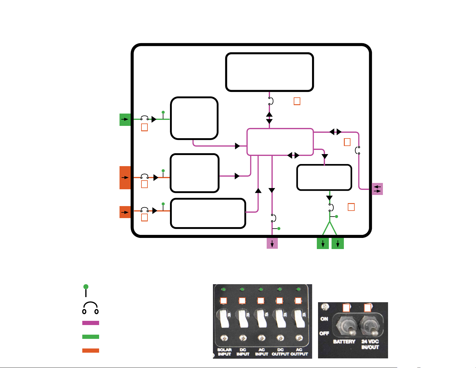
BOS 2000-120 Electrical Circuits
120 VAC circuits
Unregulated DC power input
24 VDC bus circuit
24.4–30 VDC IN/OUT
(battery expansion)
120 VAC
OUTPUT x 2
9–36 VDC INPUT
100–240 VAC INPUT
Solar Power INPUT
20 A
100 A
30 A
100 A
Solar
Charge
Controller
580 W
*30.0 V
Battery
Charger
600 W
*29.0 V
9-36VDC
Battery Charger
200 W
*28.8 V
Inverter
DC>120 VAC
2000 W
24V LiFePO4Battery
2100 Wh
24.4–30 VDC
OUTPUT
1
2
3
5
DC bus
6
7
20 A
30 A
15 A
Circuit breaker location
LED circuit activity indicator
54321
6 7
* Programmed battery charging voltage
2

BOS Electrical/Power Connections and Ventilation
24 VDC
30 A
~720 W
Front
Left
Right
100–240 VAC, 50-60 Hz
15 A max
600 W max
24.4–30 VDC
100 A max
3000 W max
9–36 VDC
20 A max
200 W max
33–100 VDC
30 A max
580 W max
DATA: CAN data and
comms from internal
battery.
GEN COMM: BOS control
of generator auto
start/stop.
Custom cables required.
Solar Input: Pin A (-), Pin C (+), Pin B (unused)
9–36 VDC Input: Pin A (-), Pin C (+), Pins B & D
(unused)
120 VAC
20 A
2400 W Max combined
Power Output
Power Input
Power Input/Output Data and Comms
24 VDC Output: Pin A (+), Pin B (-), Pin C
(unused)
DC output voltage is equal to DC bus voltage.
A
A
B
BC
C
D
A
BC
I
I
E
E
I
I = Air intake (vent has filter); E = Air exhaust (vent has no filter)
3
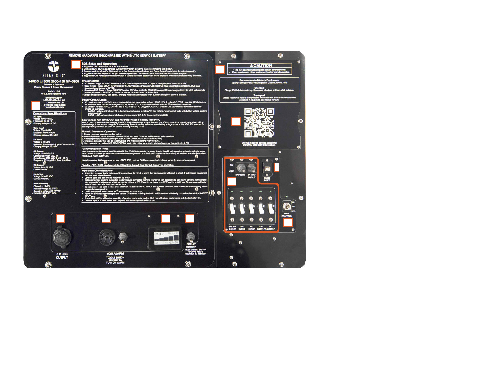
A. BOS setup and operation instructions,
Comm port information and operational
considerations
B. Operational specications. Provides limits
for AC and DC BOS circuits and internal
battery specications.
C. 5 VDC USB charging ports (x2) do not
transmit data (for device charging only).
D. AGS Alarm provides audible warning of
pending generator start. Alarm may be
silenced.
E. Internal battery status display reports battery
voltage, current (A), state of charge, status
(fault or OK), date, and time of day.
F. Battery status display refresh toggle switch
G. Breaker switch panel and circuit-activity
LEDs. See BOS 2000-120 Electrical Circuits
(page 2) for details.
H. Generator auto start/stop and manual-run
switch
I. The Tech ports provides programming
access to generator auto start/stop circuit.
Contact Solar Stik for further information.
J. Operational safety information
K. QR Code that links to this document
C
B
A
D E F
G
H
I
BOS 2000-120 Faceplate
J
K
Critical information on BOS setup, operation, and monitoring is provided
directly on the BOS Faceplate.
4

Operation Instructions
1. Ensure all breakers are OFF before connecting anything to
BOS.
2. Connect peripherals to be used as part of System (e.g.,
grid power, solar array, Novatio 1 or 2 kW generator, AC
and/or DC loads).
Note: Do not exceed load limits listed in Faceplate
Specications and elsewhere in this document.
3. Turn on BATTERY breaker to activate the BOS.
Note: BATTERY breaker must be ON for BOS to operate
properly.
4. After the battery startup info has nished, toggle Battery
DISPLAY REFRESH switch to update Battery Status
Monitor.
5. Toggle ON circuit breakers necessary to support all
connected peripherals. Green LED above breaker will
illuminate when circuit is powered.
BOS Connections and Activation BOS Charging and Discharging
Battery-only Run Times
The BOS internal battery stores 2.1 kWh of energy when fully
charged. Starting with a brand new battery, fully charged, the BOS
can support a 200 W load for ~ ten (10) hours, a 500 W load for
~ four (4) hours, or a 2000 W load for ~ one (1) hour. These times
will decrease as the internal battery ages and loses storage
capacity. This is normal for all batteries.
Low-voltage Cut Off (LVCO)
The BOS will disconnect AC loads, DC OUTPUT port and USB
charging port when the internal battery voltage drops to 24.4. If
this occurs, charge BOS immediately. Power will return to loads
automatically when battery voltage is > 25.4.
BOS Charging
Connect active AC and/or DC power source(s). Toggle ON
corresponding power input breakers.
120–240 VAC Charging: 600 W; minimum charge time from
empty is ~ 3.5 h. If AC power source is a Novatio generator, follow
directions on BOS Faceplate.
Solar Charging: 580 W max; minimum charge time from empty
is ~ 3.5 h. Charging will begin when sufcient sunlight is present.
Solar power charging speed is a function of connected solar array
power output.
9–36 VDC Charging: 200 W; minimum charge time from empty is
~ 10 h.
Internal battery is charged fully when charging current approaches
zero (0) A (see battery status sections of this document).
• For information on expanding BOS 2000 energy storage
capacity, contact Solar Stik.
• Do not connect lead-acid batteries to BOS.
• The BOS should be shaded from direct sun exposure and
sheltered from the elements as much as possible during
operation.
• Keep the case lid and connector covers closed when not
in use to prevent water and dust intrusion.
• Check the integrity of electrical connectors on a monthly
basis.
• Do not block air vents on case exterior. Clean or replace
air lters form optimum cooling.
Notice
5
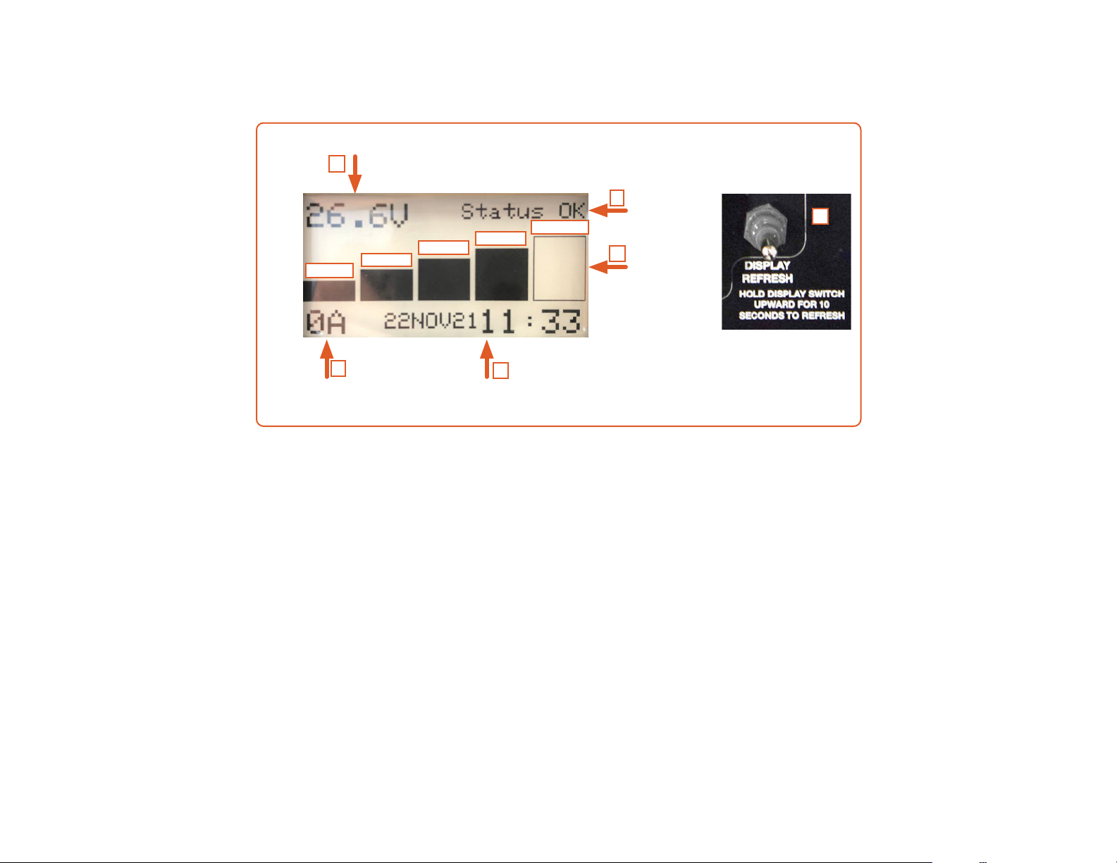
A. During normal operation, the display is updated automatically at intervals of three (3) minutes. The DISPLAY REFRESH
momentary toggle switch can be pressed and held to update the display during normal operation. The REFRESH DISPLAY switch
must be pushed and held until the home page is completely repopulated. If the button is released too soon, the display will not
populate. If this happens, wait ve (5) seconds, press and hold button until home page is repopulated.
B. A timestamp for the last “refresh” is updated and displayed, whether it occurred automatically or by pushing the refresh button.
C. The SOC is reported visually by a ve-segment “fuel gauge”. Each segment represents 20% increments up to 100%.
D. Nominal voltage = 26.4 VDC; voltage @ 100% SOC ≈ 30.4 VDC; voltage @ 0% SOC ≈ 20.0 VDC.
E. The net current (A) with respect to the batter is positive when the BOS internal battery is charging and negative when discharging.
F. If/when a battery fault occurs, the word “FAULT” appears in the upper right corner of the display. If the fault is unattended for
three (3) minutes, “FAULT” appears in large font, lling the screen. If the fault is not corrected within 60 minutes, the BOS will
enter storage mode even with the POWER switch in the ON position.
Additional information about the fault can be found on the second “page” (diagnostic screen) of the Battery Status Display, which is
accessed by toggling the Display Refresh switch twice.
Battery net
current +in/-out
Battery voltage
Timestamp of
last refresh
SOC
Indicator.
5-segment
Status
OK/FAULT
D
F
C
B
E
0-20% 21-40%
41-60% 61-80% 81-100% A
Battery Status Display Home Screen
6

An exclamation mark (“!”) will appear in the
left-most bar when SOC drops to 0% (top
left).
If/when an internal battery fault occurs,
the word “FAULT” appears in the upper
right corner of the display. If the fault is
unattended for three (3) minutes, “FAULT”
appears in large font, lling the screen (left).
If the fault is not cleared within 60 minutes,
the BOS will enter storage mode even with
the POWER switch in the ON position.
Additional information about the fault(s) can
be found on the second page of the Battery
Status Monitor (diagnostic screen).
Diagnostic Screen
To access the diagnostic screen, toggle the refresh switch once to
refresh display then a second time for the diagnostic screen. The image
below is an example of the information on the diagnostic screen that is
present when the BOS 2000 is operating normally. The SOC value range
of a new BOS will narrow as the battery cycles.
Battery Warnings and Faults Notifications
A. Battery serial number
B. CAN address for Battery
Status Monitor
C. CAN bus termination
status of battery
D. CAN address of battery
E. State of health
F. State of charge
D
A
C
B
EF
Battery Status Monitor
Startup Screens
1. Firmware version and date
2. CAN bus auto-termination status
3. CAN bus communication operational
4. Connecting to battery comms
5. Battery serial number
1
2
3
3
4
4
5
5
Screen 1
Screen 2
These two screens scroll by automatically
during startup, before the nal status
screen is populated. This is the
location where the rmware version is
documented. For more information on
the rmware, contact Solar Stik Technical
Support.
7
Notifications and Faults
Notications and fault details are found on the diagnostic screen. To access the diagnostic screen, toggle the refresh switch once to
refresh the display, then a second time for the diagnostic screen.
Notifications
Battery Offline – This notication indicates that the Battery Status Monitor lost communication with the battery. It may have taken
itself ofine to protect from overdischarge. Toggle the POWER switch to clear the notication. If the notication doesn’t clear, apply a
charging source for at least two (2) minutes. If this fails to clear the notication, contact Solar Stik.
Battery Voltage Low – “Battery voltage low” notication occurs when the BOS battery voltage falls below 20 VDC. It is only a
notication. It does not cause the battery to shut off. This notication automatically clears after charging brings voltage to > 20 VDC.
Faults
The battery may report one or more faults at a time on the diagnostic screen. If a condition other than the ones shown below appears,
contact Solar Stik for assistance. Faults place the BOS 2000 into Protected mode until the fault is corrected and the BOS returns to
Operational mode. If the fault is not cleared in 60 minutes, the BOS 2000 will enter Storage mode even if the POWER switch remains
in the ON position.
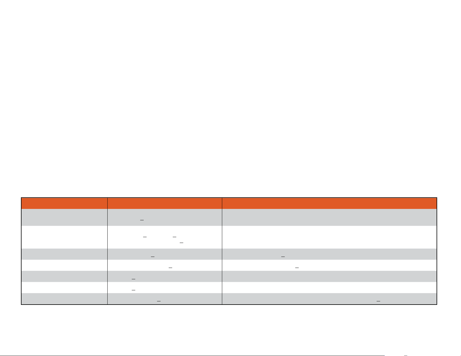
Faults reported on diagnostic screen and solutions
Fault Name Value Exceeded Clear Value
Critical Cell Overvoltage for 2
minutes Max Cell V > 4.2000 V Max Cell V < 3.8000 V
Critical Cell Undervoltage Cell Voltage < 2.00 V @ < 120 A
discharge (battery voltage < 16.0 VDC)
Automatically clears fault one time after 2-minute delay. If fault occurs again
without charging battery for 2 minutes, must clear by charging for 2 minutes or
toggling the POWER switch ON>OFF>ON.
Critical Cell Temp High Max Cell Temp > 169 ºF (76 ºC) Reduce Cell Temp to < 149 ºF (65 ºC)
Critical Board Temp High Max Elec Temp 1 or 2 > 248 ºF (120 ºC) Reduce Max Elec Temp to < 194 ºF (90 ºC)
Hardware Overload Current > 3000 A 2-minute cool down, followed by toggling the POWER switch ON>OFF>ON
Fast Software Overload Current > 1500A 30 ms 2-minute cool down, followed by toggling the POWER switch ON>OFF>ON
Software Overload Max Elec Temp 3 > 275 ºF (135 ºC) 2-minute cool down, followed by reducing Elec Temp 3 to < 194 ºF (90 ºC)
BOS Internal Battery Troubleshooting
Frequent visual monitoring of BOS 2000 Battery Status Display is the best method to ensure each battery is operating normally. If a
NOTIFICATION or FAULT is displayed on the screen take the prescribed corrective action to clear it.
8

The Battery Status Monitor will display the last status acquired before the POWER switch was turned OFF. However, battery voltage
will decrease during storage due to self-discharge. Toggle ON the POWER switch to update in-storage battery status.
In-storage BOS Internal Battery Status Information
MAINTENANCE CHARGING INSTRUCTIONS
Never store a BOS in a discharged state! Charge BOS fully before placing in storage.
Never store a BOS with the BATTERY switch in the ON position.
Temperature-dependent Self-discharge
The self-discharge rate increases as storage temperature increases. If the BOS is stored at temperatures above 90 ºF (32 ºC), then
intervals between maintenance checks and / or charges should be reduced to three (3) months.
In-storage Battery Status rRefresh: Voltage, SOC, and SOH
When the BOS BATTERY switch is OFF, the Battery Status Monitor will continue to report the last-recorded battery status; it does not
refresh automatically during storage. The Battery Status Monitor must be refreshed to report the current status while in storage.
1. Toggle ON BOS BATTERY switch.
2. The Battery Status Monitor Screen will populate with up-to-date information. This will take ~ one (1) min. with the several startup
tests/results displayed before the Status Monitor is populated.
3. Check voltage and SOC on Home screen
4. Toggle the REFRESH DISPLAY switch again to move to the Diagnostic Screen to check SOH.
In-storage Charging
If charging at any temperature lower than 68 ºF (20 ºC) the internal battery may need to heat to charge optimally. The internal heater
may require 650 W. The AC charging source provides 600 W, so the BOS internal battery may use stored energy in addition to the
AC power source to heat itself, effectively draining the battery instead of charging. This situation will be apparent if the Battery Status
Monitor reports a negative current value during the initial phase of charging and when there is no other load connected to the BOS.
1. Connect a power source to the BOS 2000. AC power will charge fastest, then solar power, then power supplied from 9–36 VDC
sources. Note: If the BOS battery was previously overdischarged, it will need to be connected to the charge source for at least two
(2) minutes, or power-cycled (toggling POWER switch ON>OFF>ON) before charge current will begin to ow.
2. Enable the charging source and allow the BOS to charge. Remember, the battery may heat itself before charging if the BOS internal
battery is colder than 68 ºF (20 ºC).
3. The BOS 2000 should continue to charge, balance, and taper until it reaches the voltage setpoint at less than 0.5 A. At this point
the BOS 2000 can be considered to be fully charged.
9


LED ON = Active Circuit
System Monitoring
54321
Battery
Voltage
Battery
Status
Date/Time
Battery Net Current
(+) = Charging
(-) = Discharging
20 40 60 80 100 SOC %
Battery Status Monitor
Home Screen
Battery Status Monitor
Data Screen
S/N = Battery Serial Number
ADDR: 80 = Internal battery CAN Address
Termination ON = CAN Termination is ON.
SOH = Internal battery state of health which is the
remaining storage capacity as a percentage of the
rated storage capacity when battery was new.
SOC = Internal battery state of charge. 100%
SOC is a fully charged battery. The range reported
will narrow as battery cycles and “learns”.
Fault (not shown)-If a fault occurs, details about
the fault will be reported on the data screen.
Toggle upward and hold DISPLAY REFRESH
switch for up to 10 seconds to update Home
Screen data.
To access data screen toggle and hold for
up to 10 seconds (home screen will update),
release switch and toggle upward and release
immediately .
Table of contents
Popular Circuit Breaker manuals by other brands


Eaton
Eaton PKE32/XTU-36-SOND533 Instruction leaflet

GE
GE GSTG024D installation instructions

Allen-Bradley
Allen-Bradley 194E installation instructions

Westinghouse
Westinghouse De-ion DM2R instructions

Analog Devices
Analog Devices Linear ADI Power LTC4249 Demo Manual

NSS
NSS Linegard GFCI INSTALLATION AND TESTING PROCEDURE