manuals.online logo
Brands
  1. Home
  2. •
  3. Brands
  4. •
  5. NSS
  6. •
  7. Circuit Breaker
  8. •
  9. NSS Linegard GFCI User manual

NSS Linegard GFCI User manual

A Ground Fault Circuit Interrupter (GFCI) is an electrical
safety device that under normal use is intended to mitigate
electric shock hazard. Use this product only within the
specified operating parameters. (Failure to do so may result
in bodily injury.) Consult a licensed electrician for assistance
on installation and repairs. Do not use this GFCI if it fails to
function as instructed. Never attempt to tamper with this
device. This GFCI must never be used as a switch to
connect or disconnect power. (Power should be
disconnected at main power feed or by secondary switch
located at the primary feed of GFCI.) This GFCI is not an
over-current protection device. (An appropriate fuse or
circuit breaker must be used in series at primary power
feed.) This GFCI does not provide protection against shocks
caused by holding both circuit conductors. This GFCI does
not provide protection against electrical shocks generated
by the conductors supplying power to the device. Note:
primary feed to GFCI is live even when GFCI is tripped.
(Power should be disconnected at main service panel
before servicing load side of GFCI.)
 Do not use this device to feed power to life support
apparatus.
 To minimize nuisance tripping:
 Do not use on swimming pool equipment
installed before 1965 NEC code.
 Do not use on electric clothes dryers or electric
ranges with frames grounded by neutral
conductor.
 Installation must comply with local and national
electrical codes (NEC).
 During installation, turn power off at the service panel to
prevent serious injuries.
What is a GFCI?
A GFCI is a device designed to interrupt power when a
ground fault (a current that takes a path to ground) exceeds
a predetermined value. This power interruption is quickly
accomplished to prevent serious injuries.
Why do we need a GFCI?
The human body is conductive to electricity, and electric
shocks can be fatal. Any electrical tool or appliance is a
potential shock hazard, especially when used near wet
locations; and this is where a GFCI is needed the most.
This is why most electrical codes require GFCI protection in
kitchens, bathrooms, garages, outdoor outlets, laundry
rooms, workshops, etc.
North Shore Safety’s GFCI, LineGard®, will offer such
protection. Its safety scope surpasses its peers to include
open supply protection (most receptacle type GFCIs do not
sense open neutral condition) as well as dual indication of
operating modes, with fault indication or power status.
How does a GFCI operate?
The GFCI constantly monitors the current-balance of the
conductors supplying power to the load. When a ground
fault occurs - by a leakage or by shock - the imbalance of
current is sensed and the GFCI trips when the ground fault
exceeds 5 mA +/- 1 mA. The tripping action must be within
a fraction of a second to prevent serious injuries.
What a GFCI cannot do:
 Will not protect the circuit’s line side.
 Will not protect you when touching two current carrying
conductors of opposite polarity (the GFCI sees this as a
load).
 Will not protect you when touching a line of another
circuit.
 Will not detect over-current.
North Shore Safety
7335 Production Drive
Mentor, Ohio 44060
Phone: 440.205.9188
Fax: 440.205.9187
Toll-free: 877.472.3348
Web: www.nssltd.com
Email: sales@nssltd.com
North Shore Safety warrants to the consumer its Line-Gard Ground Fault Circuit Interrupter (GFCI) to be free from defects in
materials and workmanship, under normal use and service, for a period of two years from date of purchase. North Shore
Safety, at its option, will repair or replace the defective GFCI without charge within 2-years of the date of the product’s
purchase provided that the defect occurred during normal use. The defective unit must be returned freight prepaid, with a RGA
(Returned Goods Authorization) including a description of the problem, and a proof of purchase date to the Quality Assurance
Dept. North Shore Safety, Ltd. 7335 Production Drive, Mentor, OH 44060.
North Shore Safety will not be liable, directly or indirectly, for installation or removal of this device, or for any personal injury, or
property damages, or incidental, indirect, or consequential damages of any kind, as a result of a defective device. The
exclusive remedy, under this warranty, is the repair or replacement of the defective device. In no case shall North Shore
Safety’s liability exceed the purchase price. This warranty is void or not covered if this device is found to be: not properly
installed, tampered with, not used according to label instructions and ratings, enclosure breached (button cover label, conduit
hubs, vent, or lid fasteners), surged, short circuited, or abused.
IMPORTANT!
THIS DEVICE MUST BE INSTALLED BY A QUALIFIED
PERSON WHO UNDERSTANDS ELECTRICAL
CIRCUITS.
Please read all the information on this sheet.
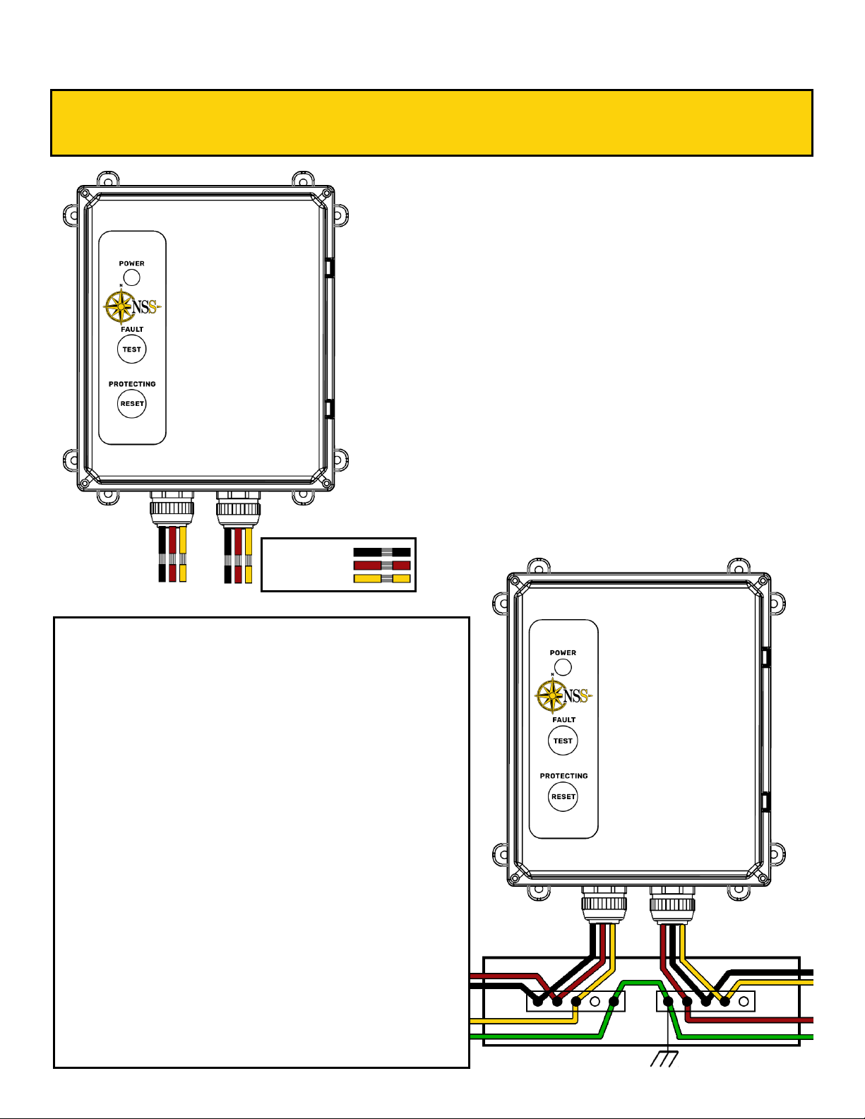
INSTALLATION AND TESTING
PROCEDURE
WARNING
North Shore Safety TWO YEAR LIMITED MANUFACTURER’S WARRANTY
192211A
192211A
INSTALLATION PROCEDURE:
DANGER: HAZARD OF ELECTRICAL SHOCK, BURN, OR EXPLOSION. Disconnect power at main
panel before you start the installation. Failure to do so will cause severe shock, personal injury or death.
Single Phase Wiring 208VAC Applicaons:
 Connect Field-Line 1 wire to GFCI’s Line 1 wire (Black) using a wire connector or
terminal block.
 Connect Field-Line 2 wire to GFCI’s Line 2 wire (Red) using a wire connector or
terminal block.
 GFCI’s Yellow line wire is cut and capped o for single phase use.
 Connect GFCI’s Load 1 wire (Black) to the protected equipment’s Line 1 run.
 Connect GFCI Load 2 wire (Red) to protected equipment’s Line 2 run.
 GFCI’s Yellow load wire is cut and capped o for single phase use.
 Bypass a properly sized grounding wire (Green) locally in the juncon box using a
wire connector, splice, or terminal block.
Three Phase Wiring 208VAC Applicaons:
 Connect Field-Line 1 wire to GFCI’s Line 1 wire (Black) using a wire connector or
terminal block.
 Connect Field-Line 2 wire to GFCI’s Line 2 wire (Red) using a wire connector or
terminal block.
 Connect Field-Line 3 wire to GFCI’s Line 3 wire (Yellow) using a wire connector or
terminal block.
 Connect GFCI’s Load 1 wire (Black) to protected equipment’s Line 1 run.
 Connect GFCI’s Load 2 wire (Red) to protected equipment’s Line 2 run.
 Connect GFCI’s Load 3 wire (Yellow) to protected equipment’s Line 3 run.
 Bypass a properly sized grounding wire (Green) locally in the juncon box using a
wire connector, splice, or terminal block.
LOAD LINE
Black= L1 (Hot)
Red= L2 (Hot)
Yellow= L3 (Hot)
Read all the instructions in this leaflet and on the
device label.
1. Identify all the features and wires (see above
drawing).
2. Identify Line wires and Load wires (grounding wire
not provided).
3. Verify that the ratings on the device match your
equipment’s ratings (Voltage, Current and
Horsepower).
4. Disconnect power at main panel.
5. Determine GFCI location and drill mounting holes
using template within this pamphlet provided.
6. Cut conductors to length and strip wires to length
7. Feed wires into junction box through appropriate
hole and secure 1” conduit ends of GFCI to
junction box or receptacle.
8. Choose the right wiring application connecting the
wires according to the above instruction. The
external grounding conductor is to be at least the
same size as power conductors.
9. Secure GFCI box to mounting panel.
LOAD LINE
192211A
Rated Voltage: 208VAC (150V to ground max) “Class-A”
Operating Voltage Range: 85% to 110% of rated
Current: Up to 60 Amps or Device Rating
Horsepower: Up to 20HP 3Ø/7.5HP 1Ø
Frequency: 60 Hz.
Trip Level: 5mA +/- 1mA
Response Time: 25ms max at 500Ω fault
Power up: Auto: Output is on immediately upon power up
Manual: Output is off immediately upon power up
Display: Illuminated TEST/RESET pushbuttons, triple indication of
Protecting & Power-out versus Fault
Enclosure: High impact polycarbonate, 8x10x4inch, NEMA 4X
Operational Temperature: -35° C to 50° C (-31° F to 122° F)
Connections: 1 inch-trade, Various UL Listed category DWTT Liquid Tight,
Hubbell P100NGYA (stocked)
Short Circuit: 10KA (panel tested), higher with appropriate fusing
Dielectric Withstand: 1500 VRMS across contact, 4000V to enclosure
Voltage Surge Withstand: 4000V/2000A 20-times per IEC 61000-4-5
Agency: Listed to UL943 (KCXS.E205630)
IMPORTANT NOTE:
*Manual configuration should be specified when automatic power up would create an unsafe condition after resto-
ration of circuit power.
**Ground connection is done external to device enclosure.
TEST PROCEDURE: After the installation has been completed, apply line side power at the branch
circuit breaker or fused disconnect. Within a few seconds the GFCI shall close its contacts showing
a GREEN illuminated RESET button, and YELLOW illuminated OUTPUT POWER light at the top
left; (RESET must first be pressed for manual models). After 10sec (self tests have completed),
press the TEST button, now only the TEST button shall be illuminated RED. If this test procedure
does not respond exactly as described, power down installation, and contact the technical support
provided. Always consult qualified electricians.
Technical Support: +1(440) 205-9188 or support@nssltd.com
Testing Procedure
Specifications
Decision Table
PGFS - 8 6 1 0 8
Product type (default)
Permanent Ground Fault Splice
Voltage
(8) 208 VAC 3Ø
Ampacity
(3) 30 Amps
(6) 60 Amps
Power Up Type
(0) Manual
(1) Automac
Fault Output
(0) None
Designator
(8) 60amp Enclosure UL Listed
1
2
3
4
5
6
7Oponal customized,
listed at end with
hyphen
(-XXX) OEM or Custom
Coding (X = number/
leer)
192211A
2.750”
70mm
AA
AA
B
B
B
B
Opon B
7.64”
194mm
Opon A
5.63”
143mm
Opon B
9.1”
231mm
Opon A
11.1”
282mm
LOAD LINE
HOT
(black)
(T1)
HOT
(red)
(T2)
HOT
(yellow)
(T3)
HOT
(black)
(L1)
HOT
(red)
(L2)
HOT
(yellow)
(L3)
LOAD LINE

Popular Circuit Breaker manuals by other brands

Leviton GCA20 installation instructions

Leviton

Leviton GCA20 installation instructions

Bticino G47XM63 manual

Bticino

Bticino G47XM63 manual

Delixi NAVIGATOR Series user manual

Delixi

Delixi NAVIGATOR Series user manual

LEGRAND Vistop 100 A manual

LEGRAND

LEGRAND Vistop 100 A manual

Siemens Sentron LMD6 Series Information and Instruction Guide

Siemens

Siemens Sentron LMD6 Series Information and Instruction Guide

Siemens SMD6 installation instructions

Siemens

Siemens SMD6 installation instructions

Siemens RCD310 Series operating instructions

Siemens

Siemens RCD310 Series operating instructions

Eaton QSA63N1 Series Instruction leaflet

Eaton

Eaton QSA63N1 Series Instruction leaflet

LEGRAND DX3 Series manual

LEGRAND

LEGRAND DX3 Series manual

hager h3 HED400G quick start guide

hager

hager h3 HED400G quick start guide

Eaton Cutler-Hammer Digitrip 1150 instructions

Eaton

Eaton Cutler-Hammer Digitrip 1150 instructions

FEDERAL PACIFIC FUSEMATIC FP25-600 instruction manual

FEDERAL PACIFIC

FEDERAL PACIFIC FUSEMATIC FP25-600 instruction manual

JACKSON.AUDIO GOLDEN BOY manual

JACKSON.AUDIO

JACKSON.AUDIO GOLDEN BOY manual

APsmart RSD-D Installation & user manual

APsmart

APsmart RSD-D Installation & user manual

GenInterlock SD-H200A quick start guide

GenInterlock

GenInterlock SD-H200A quick start guide

Siemens 3VA52-EC.1 Series operating instructions

Siemens

Siemens 3VA52-EC.1 Series operating instructions

Powell POWLVAC 15PV63SASD instructions

Powell

Powell POWLVAC 15PV63SASD instructions

ITE 5HK75 instructions

ITE

ITE 5HK75 instructions

manuals.online logo
manuals.online logoBrands
  • About & Mission
  • Contact us
  • Privacy Policy
  • Terms and Conditions

Copyright 2025 Manuals.Online. All Rights Reserved.