Powtran PB200 Series User manual

Foreword
Thank you for choosing POWTRAN design and produce brake unit. This product made by
POWTRAN is based on years of experience in professional production and sale, and designed for
feed back the regenerative consumption of motor to the brake resistor when the motor decelerates,
enhances the brake capability of the inverter, ensures the motor to stop in a short time in the
setting time.
For any problem when using this product, please contact your local dealer authorized by this
company or directly contact this company, our professionals are happy to serve you.
The end-users should hold this manual, and keep it well for future maintenance & care, and
other application occasions. For any problem within the warranty period, please fill out the
warranty card and fax it to the our authorized dealer.
The contents of this manual are subject to change without prior notice. To obtain the latest
information, please visit our website.
For more product information, please visit: http://www.powtran.com.
Powtran
December,2018

Contents
Chapter 1 Inspection and safety precautions.................................................................................. 1
1-1. Inspection after unpacking............................................................................................. 1
1-1-1. Instructions on nameplate.................................................................................. 1
1-1-2. Model instruction...............................................................................................1
1-2. .Safety precautions......................................................................................................... 2
Chapter 2 Technical specifications and installation........................................................................3
2-1. Technical specifications................................................................................................. 3
2-2. Main circuit terminal screw specifications.....................................................................3
2-3. Installation......................................................................................................................4
2-4. Dimension and installation dimension........................................................................... 4
2-5. Wiring diagram.............................................................................................................. 6
Chapter 3 Operate keyboard...........................................................................................................8
3-1. Operate keyboard instruction......................................................................................... 8
3-2. Keyboard indicators instruction..................................................................................... 8
3-3. Operation panel button instruction.................................................................................8
3-4. Keyboard display alphabet and number correspondence table...................................... 9
3-5. Examples of parameter setting....................................................................................... 9
3-5-1. Description of Function code viewing and modifying method......................... 9
Figure 3-2: Operational flow chart................................................................................................. 9
3-5-2. Viewing method of state parameters................................................................10
Chapter 4 Function parameter description....................................................................................11
4-1. Menu group.................................................................................................................. 11
4-1-1.d0 Monitoring function group...........................................................................11
4-1-2.Basic functional group...................................................................................... 11
4-1-3. Fault query....................................................................................................... 12
Chapter 5 Brake unit and brake resistor....................................................................................... 14
5-1 Brake unit...................................................................................................................... 14
5-1-1. Brake voltage selection is based on below two conditions:.............................14
5-1-2. Brake resistor resistance selection................................................................... 14
5-1-3. Brake unit power selection...............................................................................14
5-1-4. Inverter input voltage level specification and selection reference...................15
Chapter 6 Abnormal diagnosis and treatment...............................................................................17
Chapter 7 Maintenance and repair................................................................................................18
7-1.Inspection and maintenance.......................................................................................... 18
7-2.Parts for regular replacement........................................................................................ 18
7-3.Storage...........................................................................................................................19
Chapter 8 Quality assurance.........................................................................................................20
Product information feedback..................................................................................................- 22 -

1
Chapter 1 Inspection and safety precautions
POWTRAN brake unit have been tested and inspected before leaving factory. After
purchasing, please check if its package is damaged due to careless transportation, and if the
specifications and model of the product are consistent with your order requirements. For any
problem, please contact your local authorized POWTRAN dealer or directly contact this company.
1-1.Inspection after unpacking
※Check if that packing container contains this unit, one manual and one warranty card.
※Check the nameplate on the side of the frequency inverter to ensure that the product you
have received is right the one you ordered.
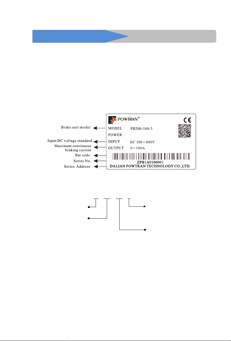
1-1-1.Instructions on nameplate
Figure 1-1:Nameplate description
1-1-2.Model instruction
Powtran Brake unit
PB 200 100 3
M axim um continuous
braking current
100:100A
040:40A
Series code:
PB200 series
Input voltage grade
2:220VAC
3:380VAC
4:480VAC
Figure 1-2:Model description

Chapter 1 Inspection and safety precautions
2
1-2..Safety precautions
Safety precautions in this manual are divided into the following two categories:
Danger: the dangers caused by failure to perform required operation, may result in
serious injury or even death;
Caution:the dangers caused by failure to perform required operation, may result in
moderate injury or minor injury, and equipment damage;
Process
Type
Dangerous
● Only well-trained personnel are allowed to use this unit.
● Fix the screw when connecting, or the loose connection will lead fire or creepage.
● Grounding terminal should be reliable grounding braking unit, or get an electric
shock risk.
●Do not touch the brake unit, the internal spares and printing board after the brake unit
is connected, otherwise it will lead to electric shock. There is high voltage direct
current inside.
●Don't let the cable damage from weight hanging and over load, or get an electric
shock risk.
●The unit and brake resistor should be installed on the medium with flame retardancy
(such as metal), away from combustible material, otherwise may cause fire
●Please check the wiring is correct before operation. Please confirm whether the input
DC voltage and brake unit voltage same level; Whether Input terminal (+, -) and
resistance terminal (RB1, RB2) connection position is correct; And check the
peripheral circuit of the connected to the drive for short circuit phenomenon, whether
the line is fastening, otherwise cause damage of drive.
●Please check whether master-slave choice and voltage grade Settings are correct.
●During the running, do not touch any spares inside.
●The repairs and maintenance task can be performed only when the inverter bus
voltage is lower than DC 36V, Power off more than ten minutes.Otherwise, the
residual charge from capacitor would cause personal injury!
Attention
● Do not use any brake unit and brake resistor lack of or with damaged spares.
●Do not touch the internal spares for there are CMOS spares on the control card of the
brake unit. Otherwise it will damage the spares.
●When many pieces brake units installed in parallel when used in the same case, please
install the fan or other cooling device.
●Ensure the right setting of brake unit and brake resistor.
●Do not make voltage resistance test on the brake unit, or it will lead semiconductor
spares damaged in the main circuit of the brake unit.
●Braking resistor should be temperature protection and other protection, if the brake
resistance keep hot which caused by the failure of the brake unit. fever, necessary to
isolate itself, does not automatically isolation caused any accident not be burdened
by Powtran.
●Please refer to the content in the manual when analyze and manage the fault of the
brake unit. Any modification to the brake unit is not allowed otherwise the life
harm and property loses will not be burdened by Powtran.
●This product is the accessories of the inverter, if it is used improperly which would
not only do damage to itself but also to the inverter. Please pay much attention to
this.
●Only the well-trained personnel are allowed to use this unit, and such personnel must
read through the parts of this manual relating to the safety, installation, operation and
maintenance before using the unit. The safe operation of this unit depends on correct
transport, installation, operation and maintenance.
Note: When brake unit work with powtran inverter,powtran will responsible for quality, If the
brake unit work for other project, Please make your own insurance related domestic property
insurance, in order to get better compensation from insurance company.

3
Chapter 2 Technical specifications and installation
2-1.Technical specifications
Brake unit model
Starting brake voltage (V)
Maximum continuous braking
current (A)
PB200-040-2
350
40
PB200-050-2
350
50
PB200-075-2
350
75
PB200-100-2
350
100
PB200-180-2
350
180
PB200-250-2
350
250
PB200-040-3
670
40
PB200-050-3
670
50
PB200-075-3
670
75
PB200-100-3
670
100
PB200-180-3
670
180
PB200-250-3
670
250
PB200-040-4
760
40
PB200-050-4
760
50
PB200-075-4
760
75
PB200-100-4
760
100
PB200-180-4
760
180
PB200-250-4
760
250
2-2.Main circuit terminal screw specifications
Brake unit model
Main circuit screw
specification
Tightening torque (Nm)
PB200-040-2
M5
2~2.5
PB200-050-2
M5
2~2.5
PB200-075-2
M5
2~2.5
PB200-100-2
M5
2~2.5
PB200-180-2
M8
9~11
PB200-250-2
M8
9~11
PB200-040-3
M5
2~2.5
PB200-050-3
M5
2~2.5
PB200-075-3
M5
2~2.5
PB200-100-3
M5
2~2.5
PB200-180-3
M8
9~11
PB200-250-3
M8
9~11
PB200-040-4
M5
2~2.5

Chapter 2 Technical specifications and installation
4
PB200-050-4
M5
2~2.5
PB200-075-4
M5
2~2.5
PB200-100-4
M5
2~2.5
PB200-180-4
M8
9~11
PB200-250-4
M8
9~11
2-3.Installation
2-3-1 Working environment
The breaking unit shall be installed in the room where it is well ventilated, the wall mounted
installation shall be adopted.
2-3-2Installation environment
1. Ambient temperature -10 ° C ~ 50 ° C. If exceeding 40 °C, derating at a rate of 3% derating
for every 1 °C. It is not recommended to use in an environment above 50 °C.
2. Prevent electromagnetic interference and keep away from interference sources.
3. Prevent the intrusion of dust, cotton wool and fine metal powder.
4. Prevent the intrusion of oil, salt and corrosive gases.
5. Avoid vibration.
6. Avoid high temperature and humidity and no rain dripping, humidity less than 90% RH (No
condensation).
7. It is forbidden to use under hazardous environmental conditions such as flammability,
flammability, explosive gas, liquid or solid.
8. The braking resistor cannot be installed close to the air inlet of the brake unit.
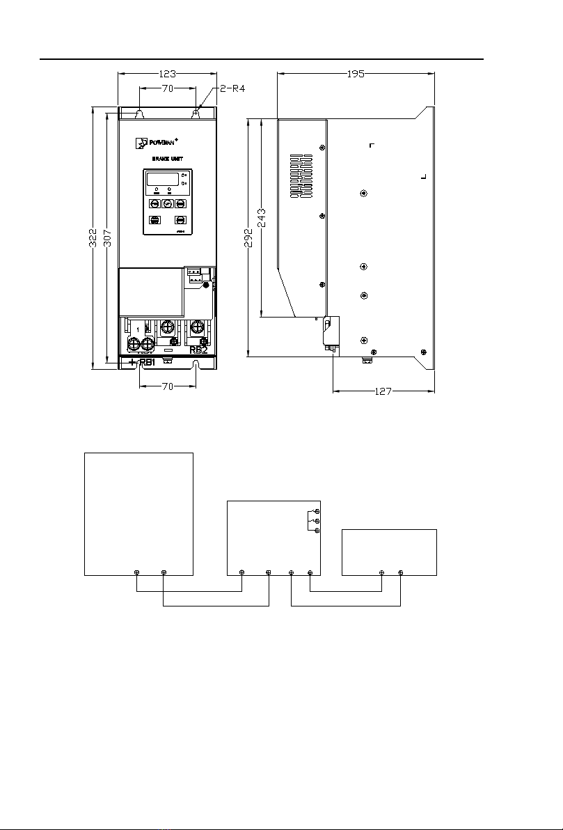
2-4.Dimension and installation dimension
Shell base
Shell cover
Fan
Wind into plate
Indicator light
Control keyboard
Figure 2-1:40-100A the braking unit sketch

Chapter 2 Technical specifications and installation
5
Fan
Case base
Case cover
Control keyboard
Indicator light
Air inlet board
Figure 2-2:180-250A the braking unit sketch
80
110
202
80 7
216
186
216
140
2-R3.5
Figure 2-3:40-100A Braking unit installation dimension
Chapter 2 Technical specifications and installation
6
Figure 2-4:180-250A Braking unit installation dimension
2-5.Wiring diagram
+-+-RB1 RB2
TA
TB
TC
Frequency
inverter
Brake unit
Brake resistor
Figure 2-5:Single brake unit wiring diagram

Chapter 2 Technical specifications and installation
7
Frequency
inverter
Brake unit
+-+-RB1 RB2 +-RB1 RB2
Brake resistor
Host Slave
COM PIO
COM PIO
(F0.06=0)
(F0.06=1)
TA
TB
TC
TA
TB
TC
Brake resistor
Brake unit
Figure 2-6:Figure multi-brake units parallel connection diagram
NOTE:
1. The connection cable of frequency inverter and brake unit shall be twisted with two lines,
the longest of which shall not exceed 5m
2. The distance of the connection between the brake resistor and brake unit should less than
10m, should use heat-resistant wires.
3. +/P+ is the positive end of DC BUS in the frequency inverter, -P- is the negative end.
4. Output relay TA/TB/TC,TA-TC normally open and TB-TC close. Relay drive
ability. :normally close 3A/AC 250V,normally open.5A/AC 250V.
5. Wrong connection of main circuit will cause damage of brake unit and frequency inverter.
6. Please do not touch the brake unit when it is working, to avoid scald.
2-5-1. Brake unit main circuit terminal and making circuit terminal
1、Main circuit terminal
RB1 RB2
(+)
(-)
Figure 2-5. Brake unit main circuit terminal
Terminal mark
Function instruction
(+)
Connect the positive terminal of the inverter DC BUS.
(-)
Connect the negative terminal of the inverter DC BUS.
RB1、RB2
External connect brake resistor terminal
PE
Brake unit ground terminal
2. Control circuit terminal
COM PIO
TA TB TC
Figure 2-6. Control circuit terminal
Terminal mark
Function instruction
COM
Brake unit control circuit ground.
PIO
Brake units work in parallel in input or output terminal, when multi brake
unit used in parallel, send control signal through the terminal that braking
unit can run simultaneously.
TA/TB/TC
Fault output terminals, when braking unit failure, send out fault alarm
signal. TA - TC for normally open and TB - TC closed
8
Chapter 3 Operate keyboard
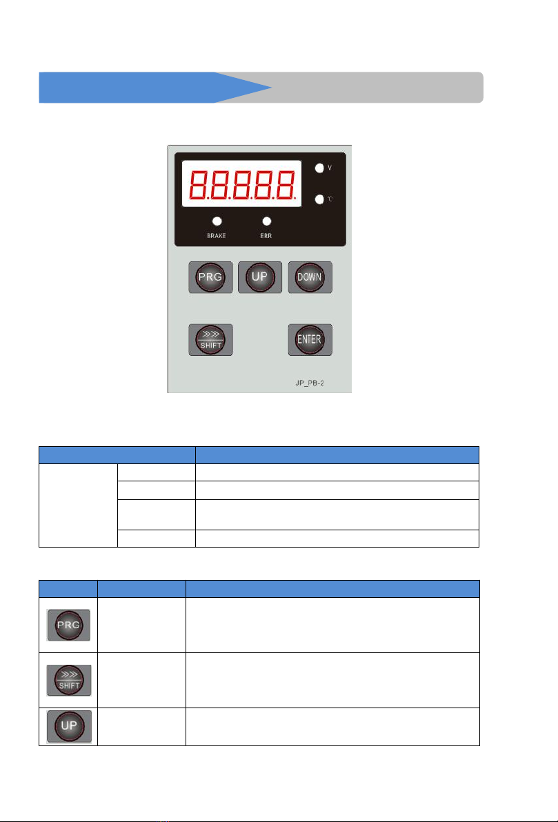
3-1.Operate keyboard instruction
Figure 3-1:Operate keyboard display
3-2.Keyboard indicators instruction
Indicator mark
Name
Status light
V
Brake unit input voltage
℃
On :IGBT temperature
BRAKE
On :Brake unit on brake status .
Dull : Brake unit on standby status
ERR
Off :Fault indicator light
3-3.Operation panel button instruction
Mark
Name
Function
Parameter setting /
ESC key
* Enter the first level menu parameters changes state.
* Exit function data modify.
* Exit from submenu or function item menu to status display
menu
Shift key
* Under the standby display interface and brake display interface,
display parameters can be selected circularly. When modify a
parameter, customer can select the modification bit of the
parameter
Increasing key
*Date and function increasing key.
Chapter 3 Operate keyboard
9
Descending key
* Date and function descending key.
Confirm key
*Step by step into the menu screen, set parameter confirmation.
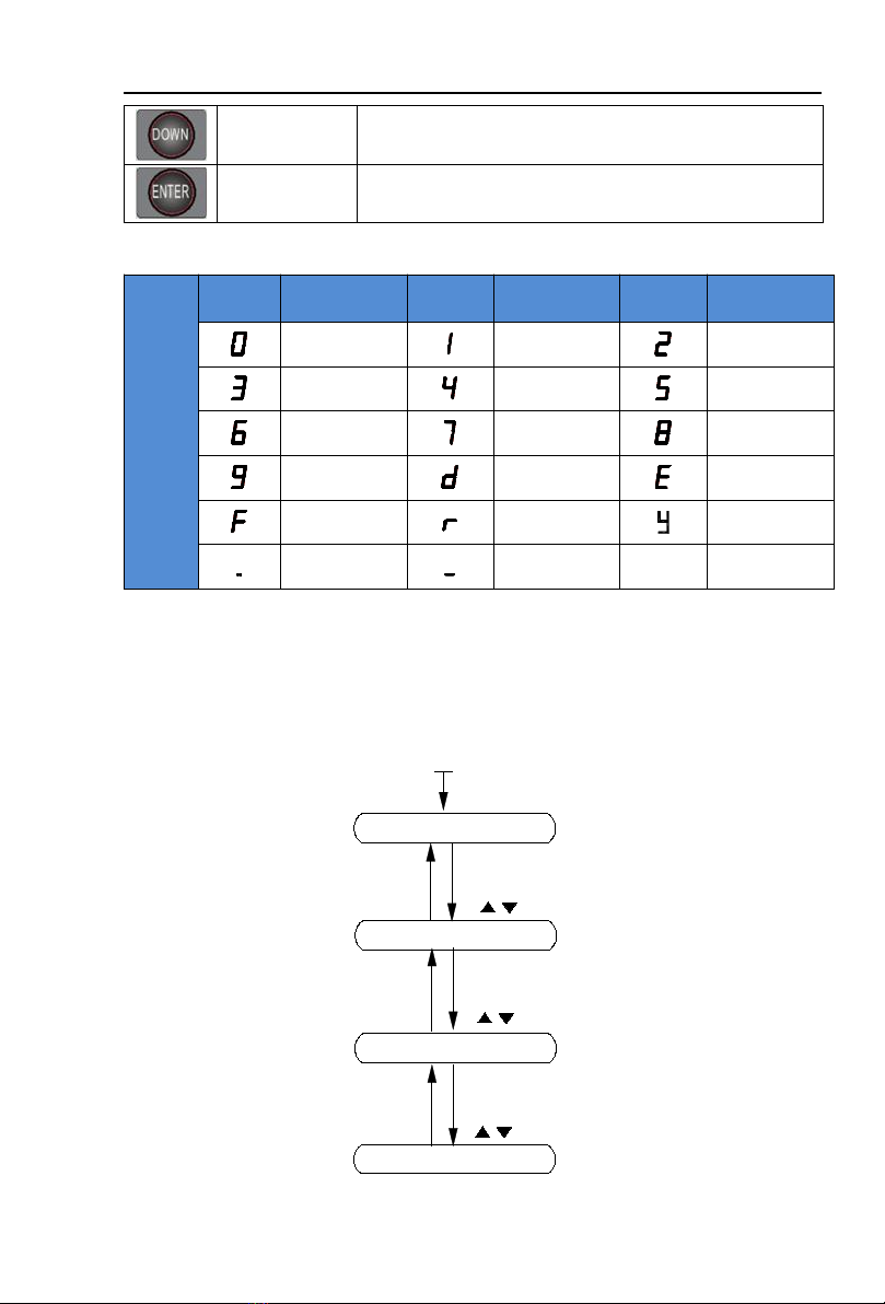
3-4.Keyboard display alphabet and number correspondence table
Digital
display
area
Display
Alphabet
Correspondence
Alphabet
Display
Alphabet
Correspondence
Alphabet
Display
Alphabet
Correspondence
Alphabet
0
1
2
3
4
5
6
7
8
9
d
E
F
r
y
.
-
3-5.Examples of parameter setting
3-5-1.Description of Function code viewing and modifying method
PB200 operation panel adopts three-level menu structure to set parameters and other
operations. The three-level menus are: function parameter group (first-level menu) function code
(second-level menu) function code setting value (third-level menu). The operation flow is shown in
the figure.
Standby parameter show
PRG
Change parameter
group
PRG
First-level menu display
ENTER
Change parameter
function choice
PRG
ENTER
Change function
parameter value
PRG
ENTER
Power on
Second-level display
Third-level display
Figure 3-2: Operational flow chart
Chapter 3 Operate keyboard
10
Description: In the operation of three-level menu, you can press PRG or ENTER to return to
the second-level menu. The difference between the two is: Press ENTER key to save the set
parameters and return to the secondary menu, and automatically transfer to the next function code;
Pressing the PRG key directly returns to the secondary menu, without storing parameters, and
returns to the current function code.
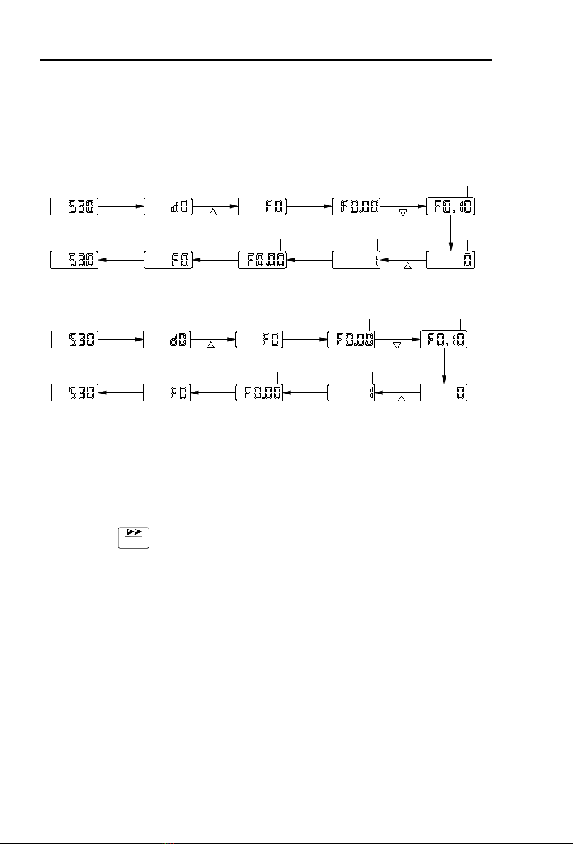
Example 1: The starting voltage of braking is modified to 380V, assuming that the input
voltage of the braking unit is 530VDC.
Change F0.00 from 670V to 660V
Press
Flash
Press
PRG
Press
ENTER
Press
ENTER
Press
ENTER
Press
PRG
Press
Press
Flash
Flash
Flash
Flash
Press
ENTER
Example 2. Restore factory parameters
Press
Flash
Press
PRG
Press
ENTER
Press
ENTER
Press
ENTER
Press
ENTER
Press
PRG
Press
Press
Flash
Flash
Flash
Flash
In the third menu state, if the parameter has no flicker bits, it means that the function code can
not be modified. The possible reasons are as follows:
1) The function code is an unmodifiable parameter. For example, the actual detection
parameters, operation record parameters and so on.
2) The function code can not be modified in the running state, and can not be modified until
the downtime.
3-5-2.Viewing method of state parameters
During shutdown or operation, the temperature and brake unit input voltage can be separated
by the shift key.
SHIFT

11
Chapter 4 Function parameter description
4-1. Menu group
Attention:
"★": In the braking state, the setting value of this parameter can not be changed;
"●": The actual detection value can not be changed;
"☆": It can be changed when it is in downtime or running state.
Group d is the monitoring function parameter, Group F is the basic function parameter, Group
Y1 is the fault history query.
4-1-1.d0 Monitoring function group
Paramet
er Code
Parameter name
Paramet
er name
d0.00
Braking unit input voltage / Inverter bus voltage
V
Braking unit input voltage
d0.01
Module temperature
℃
Detection value of radiator temperature of inverter module
d0.02
Software version
-
Display current brake unit software version number
4-1-2.Basic functional group
Code
Parameter name
Setting range
Factory
setting
Cha
nge
F0.00
Braking start voltage
300V~2500V
Model
confirmed
☆
This parameter is used to set the starting braking voltage of the braking unit.
220V voltage level, default braking voltage is 350V;
380V voltage level, default braking voltage is 670V;
480V voltage level, default braking voltage is 760V;
F0.01
Braking hysteresis voltage
0V~100V
20V
☆
This parameter is used to set the hysteresis voltage during braking.
Generally when setting braking start voltage and braking stop voltage, there must be a
hysteresis loop. Such as settings F0.00=670V,F0.01=20V,when the bus voltage d0.00 is higher
than F0.00, start braking. When the bus voltage d0.00 is lower than (F0.00-F0.01), stop braking.
When the original state is in braking state, and the value of d0.00 is within F0.00 ~ (F0.00-
F0.01), the braking state is maintained.
F0.02
Default brake voltage selection
0~2
1
★
This parameter is used to set the default braking voltage for different voltage levels.
When setting to 0, corresponding to 220V voltage level, the default braking voltage is 350V;
When setting to 1, corresponding to 380V voltage level, the default braking voltage is 670V;
When setting to 2, corresponding to 480V voltage level, the default braking voltage is 760V;
F0.03
Braking rate
0%~100%
100%
☆
This parameter is used to select the braking rate.
When braking rate is set to 100%, it shows that the braking is fully open, at this time the
braking effect is the best, with the fastest voltage drop, but the brake resistor temperature rises
quickly.
When the braking rate is set to 0%, it shows that the braking is turned off, at this time even
if it reaches the braking condition, the braking does not work.

Chapter 4 Function parameter description
12
F0.04
Voltage modulation factor
0%~200%
100%
☆
This parameter can be used to adjust the d0.00 bus voltage detection value.
That is d0.00=DC BUS input voltage =d0.00*F0.04.
F0.05
Relay output function selection
0~4
0
☆
Relay function instructions below:
Setting
value
Function
Description
0
No output
The relay outputs no action.
1
In Braking
In braking state, the relay outputs ON signal.
2
Braking feedback fault
(IGBT short circuit)
In braking process, it feedback IGBT short-circuit fault, the
relay output ON signal.
3
Over-temperature alarm
When the module temperature exceeds 85℃, the over-
temperature alarm signal is generated, the relay outputs ON
signal.
4
Fault output
When brake feedback fault or over-temperature fault
occurs, the relay output ON signal.
F0.06
Master and slave selection
Slave
0
1
★
aster
1
This parameter is used for the parallel function, setting the braking unit as master or slave. If
you do not use the parallel function, the system single-set default unit host.
F0.07
Temperature hysteresis value
0~50
3
☆
This parameter is used to set the hysteresis value of the temperature. The default temperature
alarm value for the brake unit is 85 ℃. If the temperature hysteresis value is set to 3 ℃, when
there is not over temperature fault, if only the temperature exceeds 85 ℃, it alrms. If over
temperature fault occurs, the alarm is canceled only when the temperature drops below 82 ℃.
F0.08
Total power-on time
0~50000h
-
●
Display the total power-on time of braking unit since it is out of factory.
F0.09
Total running time
0~50000h
-
●
F0.10
Parameter
initialization
No operation
0
0
★
The parameters restored to factory value
1
Clear record information
2
1: Restore to the factory setting (F0.10 = 1), most of the brake unit parameters are restored to
factory setting, except default braking voltage level (F0.02), fault record information, total power-
on time, total running time.
2: Clear the record information (F0.10 = 2) Clear the fault record information, total power-on
time, total running time of the braking unit.
4-1-3. Fault query
Code
Parameter name
Setting range
Factory
setting
Cha
nge
y1.00
Type of the first fault
0~2
-
●
y1.01
Type of the second fault
0~2
-
●
y1.02
Type of the third(at last) fault
0~2
-
●
Record the type of the last three faults of PB200, 0 for no fault. Please refer to the related

Chapter 4 Function parameter description
13
instructions for the possible causes and solutions for each fault code.
Failure type table:
No.
Failure type
0
No fault
1
Braking feedback fault (IGBT short circuit)
2
Over temperature fault
y1.03
Bus voltage of the third fault
Bus voltage of the last fault
●
y1.04
Temperature of the third fault
Temperature of the last fault
●
y1.05
Braking rate of the third fault
Braking rate of the last fault
●
y1.06
Power on time of the third fault
Power on time of the last fault
●
y1.07
Running time of the third fault
Running time of the last fault
●
y1.08
Bus voltage of the second fault
Bus voltage of the previous fault
●
y1.09
Temperature of the second fault
Temperature of the previous fault
●
y1.10
Braking rate of the second fault
Braking rate of the previous fault
●
y1.11
Power on time of the second fault
Power on time of the previous fault
●
y1.12
Running time of the second fault
Running time of the previous fault
●
y1.13
Bus voltage of the first fault
Bus voltage before the previous fault
●
y1.14
Temperature of the first fault
Temperature before the previous fault
●
y1.15
Braking rate of the first fault
Braking rate before the previous fault
●
y1.16
Power on time of the first fault
Power on time before the previous fault
●
y1.17
Running time of the first fault
Running time before the previous fault
●

14
Chapter 5 Brake unit and brake resistor
5-1 Brake unit
5-1-1.Brake voltage selection is based on below two conditions:
(1) According to the input voltage level of inverter , choose the brake unit with relative
voltage level
(2) According to the required braking power when inverter is braking , choose the brake
unit with relative power .
The principle of brake unit power selection is that the power of brake unit is greater than the
braking power . in the case where the braking power is not specified , please estimate according to
below ways :
Pb=P*Td*K
In this formula:Pb-----braking power;
P----- motor power
K----- mechanical energy conversion efficiency,the general value is 0.7
Td---- ratio of brake torque to motor rated torque
Td values vary in different systems , as shown in the following table.
Common
applications
Elevator lift
crane
Uncoiler and
recoiling
Large inertia equipment
that requires quick
stopping
Ordinary
inertial load
Td value
100%
120%
120%
80%
5-1-2.Brake resistor resistance selection
When it is braking, the regenerative energy of the motor is almost consumed on the brake
resistor ,according to the formula:
U*U/R=Pb
In the formula:U----- braking voltage in stable braking system
(vary in different systems , for 220VAC system usually choose 380v; for 380VAC system
usually choose 700V, for 480VAC system usually choose 800V)
Note: when the value of R is less than the minimum resistance of each voltage level, multiple
brake units are required.
5-1-3.Brake unit power selection
In theory , the power of brake resistance is same as the braking power , but considering
derating is 70%. according to formula:
0.7*Pr=Pb*ED
In the formula:Pr-----brake unit power
ED----- braking frequency , the proportion of braking process in the whole working process
Common application
ED value
Uncoiler and recoiling
20%~30%
Accidental braking load
5%
Elevator
20%~30%
Lifting machinery , centrifuge
50%~60%
Injection molding machine
5%~10%
General occasion
10%
In the above table, the recommended braking unit and braking resistor resistance can meet
various inverters with ED=0~100%. And the power of the braking resistor depends on the
application conditions.

Chapter 5 Brake unit and brake resistor
15
5-1-4.Inverter input voltage level specification and selection reference
1. This table is the selection reference of 220V inverter, according to the brake unit DC
operating point 350V, braking frequency ED = 10%, and braking torque 100%.
Inverter
power (kW)
Brake unit
Brake resistor (100% brake torque)
Specification
Quantity (pcs)
Specification
Quantity
(pcs)
15
PB200-040-2
1
≥9Ω/2kW
1
18.5
PB200-040-2
1
≥9Ω/2kW
1
22
PB200-050-2
1
≥7Ω/3kW
1
30
PB200-075-2
1
≥5Ω/3kW
1
37
PB200-075-2
1
≥5Ω/4kW
1
45
PB200-100-2
1
≥4Ω/5kW
1
55
PB200-100-2
1
≥4Ω/6kW
1
75
PB200-180-2
1
≥2Ω/8kW
1
93
PB200-180-2
1
≥2Ω/10kW
1
110
PB200-180-2
2
≥2Ω/7kW
2
132
PB200-180-2
2
≥2Ω/8kW
2
160
PB200-100-2
2
≥2Ω/9kW
2
2.This table is the selection reference of 380V inverter, according to the brake unit DC
operating point 670V, braking frequency ED = 10%, and braking torque 100%.
Inverter
power (kW)
Brake unit
Brake resistor (100% brake torque)
Specification
Quantity (pcs)
Specification
Quantity
(pcs)
18.5
PB200-040-3
1
≥17Ω/2kW
1
22
PB200-040-3
1
≥17Ω/3kW
1
30
PB200-040-3
1
≥17Ω/3kW
1
37
PB200-040-3
1
≥17Ω/4kW
1
45
PB200-050-3
1
≥14Ω/5kW
1
55
PB200-075-3
1
≥9Ω/6kW
1
75
PB200-100-3
1
≥7Ω/8kW
1
93
PB200-100-3
1
≥7Ω/10kW
1
110
PB200-180-3
1
≥4Ω/12kW
1
132
PB200-180-3
1
≥4Ω/15kW
1
160
PB200-180-3
1
≥4Ω/18kW
1
187
PB200-100-3
2
≥7Ω/10kW
2
200
PB200-100-3
2
≥7Ω/11kW
2
220
PB200-180-3
2
≥4Ω/12kW
2
250
PB200-180-3
2
≥4Ω/13kW
2
280
PB200-180-3
2
≥4Ω/15kW
2
315
PB200-180-3
2
≥4Ω/17kW
2
355
PB200-180-3
3
≥4Ω/13kW
3
400
PB200-180-3
3
≥4Ω/14kW
3

Chapter 5 Brake unit and brake resistor
16
3.This table is the selection reference of 480V inverter, according to the brake unit DC
operating point 760V, braking frequency ED = 10%, and braking torque 100%.
Inverter
power (kW)
Brake unit
Brake resistor (100% brake torque)
Specification
Quantity (pcs)
Specification
Quantity (pcs)
18.5
PB200-040-4
1
≥19Ω/2kW
1
22
PB200-040-4
1
≥19Ω/3kW
1
30
PB200-040-4
1
≥19Ω/3kW
1
37
PB200-040-4
1
≥19Ω/4kW
1
45
PB200-050-4
1
≥16Ω/5kW
1
55
PB200-075-4
1
≥11Ω/6kW
1
75
PB200-075-4
1
≥11Ω/8kW
1
93
PB200-100-4
1
≥8Ω/10kW
1
110
PB200-100-4
1
≥8Ω/12kW
1
132
PB200-180-4
1
≥5Ω/14kW
1
160
PB200-180-4
1
≥5Ω/18kW
1
187
PB200-180-4
1
≥5Ω/20kW
1
200
PB200-180-4
1
≥5Ω/22kW
1
220
PB200-100-4
2
≥8Ω/12kW
2
250
PB200-180-4
2
≥5Ω/14kW
2
280
PB200-180-4
2
≥5Ω/15kW
2
315
PB200-180-4
2
≥5Ω/17kW
2
355
PB200-180-4
2
≥5Ω/19kW
2
400
PB200-180-4
2
≥5Ω/21kW
2
Table of contents
Other Powtran Circuit Breaker manuals

Popular Circuit Breaker manuals by other brands


Siemens
Siemens NXPLUS C Installation and operating instructions

Delixi
Delixi NAVIGATOR DZ47L Series user manual

TEL
TEL TAVRIDA ELECTRIC VCB15 LD user guide

ABB
ABB HD4/R Installation and operating instructions

CHNT Power
CHNT Power Smart Meter CPS1000 user manual

Eaton
Eaton Cutler-Hammer Digitrip RMS 810 instructions