Trannergy TRB010KTL User manual
User Manual
TRB4000TL/TRB5000TL/TRB6000TL/TRB8000TL/TRB9000TL/
TRB010KTL

User Manual 1
Contents
Copyright Declaration................................................................................................................... 3
1. Introduction............................................................................................................................... 4
1.1. Introduction........................................................................................................................ 4
1.2. How to Use this manual..................................................................................................... 4
1.3. Applied Designations (Warning, Caution, Note)............................................................... 4
1.4. Important Safety Information............................................................................................. 4
1.5. General Safety Rules for Working on Electrical Equipment ............................................. 5
1.6. System Sizing..................................................................................................................... 6
2. Technical Description of Inverters............................................................................................ 7
2.1. Mechanical design.............................................................................................................. 7
2.2. Electrical system design..................................................................................................... 8
2.3. The illustration of derating and limit the input power........................................................ 8
3. Operation mode illustration of the inverter............................................................................... 9
3.1. Wait mode.......................................................................................................................... 9
3.2. Check mode........................................................................................................................ 9
3.3. Normal mode...................................................................................................................... 9
3.4. Fault mode........................................................................................................................ 10
3.5. Flash mode....................................................................................................................... 10
3.6. Shut down......................................................................................................................... 10
4. Installation and startup............................................................................................................ 11
4.1. Installation precaution...................................................................................................... 11
4.2. Install steps....................................................................................................................... 11
4.3. Electrical connection........................................................................................................ 13
4.3.1. Connection to the grid (AC output)........................................................................... 13
4.3.2. Connection to PV generator (DC input).................................................................... 15
4.4. Test run............................................................................................................................. 18
5. Human Machine Interface....................................................................................................... 19
5.1. Control and Display Panel................................................................................................ 19
5.2. LED Display..................................................................................................................... 20
5.3. LCD Display .................................................................................................................... 21

2User Manual
5.4. Function Keys .................................................................................................................. 24
5.4.1. Configure................................................................................................................... 24
5.4.2. Energy yield .............................................................................................................. 26
5.4.3. Inverter state.............................................................................................................. 27
5.4.4. Device Information ................................................................................................... 27
5.4.5. log Information.......................................................................................................... 27
5.5. Display of Fault................................................................................................................ 28
6. Communication and Monitoring............................................................................................. 29
6.1. Communication Interfaces ............................................................................................... 29
6.2. Communication................................................................................................................ 29
6.2.1. RS-232 Communication for Three inverter type....................................................... 29
6.2.2. RS-485/422 Communication..................................................................................... 30
6.2.3. WiFi/GPRS/Ethernet Communication...................................................................... 30
6.2.4. USB Communication ................................................................................................ 31
6.3. Monitoring........................................................................................................................ 31
7. Maintenance and Repair.......................................................................................................... 32
7.1 Routine maintenance......................................................................................................... 32
7.2 Notes of maintain or service.............................................................................................. 32
7.3 Safety for maintain or service ........................................................................................... 32
8. Technical data ......................................................................................................................... 33
9. Qualification............................................................................................................................ 34
10. Contact Information .............................................................................................................. 35
Appendix A: FAQ (Frequently asked questions)........................................................................ 36
Appendix B: Abbreviation.......................................................................................................... 37

User Manual 3
Copyright Declaration
The copyright of this manual belongs to Trannergy Co., Ltd.. Any corporation or
individual should not plagiarize, partially copy or fully copy it (including software,
etc.), and no reproduction or distribution of it in any form or by any means. All rights
reserved. Trannergy reserves the right of final interpretation. This manual is subject to
change according to user’s or customer’s feedback. Please check latest version at:
http://www.trannergy.com.

4User Manual
1. Introduction
1.1. Introduction
This manual describes Trannergy solar inverters TRB4000TL/ 5000TL/ 6000TL/
8000TL/ 9000TL/010KTL. These products are among the most technologically
advanced and efficient inverters on the market and are designed to ensure a stable
power supply for many years.
The TRB inverters is a transformerless based inverter.
1.2. How to Use this manual
Please read the safety instructions in this manual first. Throughout the manual it is
assumed that the reader is familiar with AC and DC installations and knows the
rules and regulations for electrical equipment and for connecting it to the utility
AC grid. It is especially important to be familiar with the general safety rules for
working with electrical equipment.
1.3. Applied Designations (Warning, Caution, Note)
Throughout the manual important information is shown at different levels
depending on the character of the information, as shown here:
Safety information important for human safety. Violation of warnings may
result in injury to persons or death.
Information important for the protection of property. Violation of this type
of information may cause damage and loss of property.
Useful additional information or “Tips and Tricks" on specific subjects.
1.4. Important Safety Information
Read this before installing, operating or maintaining the inverter.
Before installation:
Check for damage to inverter and packaging. If you are in doubt, please
contact your supplier before installing the inverter. Check the voltages of the
solar modules and make sure they are within the limits of the Trannergy
inverter specifications before connecting them to the inverter.

User Manual 5
Installation:
Only trained and authorized personnel familiar with local electrical codes
may install the inverter. For optimum
safety, please follow the steps
described in this manual. Keep in mind that the inverter has two voltage
carrying sides, the PV input and the AC grid.
Disconnecting the inverter:
Always disconnect t
he AC line first! Afterwards disconnect the PV lines.
Note that
the inverter can still be charged with very high voltages at
hazardous levels even when it is disconnected from grid/mains and solar
modules. Wait at least 5 min. before proceeding, after having disconnected
from grid and PV panels.
operating the inverter:
Before connecting the AC grid to the inverter, make sure that the installation
cover is mounted again. The inverter must not be open during operation.
Maintenance and modification:
Only authorized personnel are allowed to repair or modify the inverter. To
ensure
optimum safety for user and environment, only the original spare
parts available from your supplier should be used.
Functional safety parameters:
Unauthorized changes of functional safety parameters may cause injury or
accidents to people or inverter. Additionally it will lead to the cancelling of
all inverter operating approval certificates. The Trannergy inverters in the
TRB range are all designed according to international safety requirements.
If non-original spare parts are used, the compliance with CE guidelines in
respect of electrical safety, EMC and machine safety is not guaranteed.
1.5. General Safety Rules for Working on Electrical Equipment
All persons installing, maintaining or servicing inverters should be trained in and
have experience with the general safety rules to be observed when working on
electrical equipment.
Installation and service personnel should also be familiar with local requirements,
rules and regulations as well as safety requirements.
To provide a general guideline for safety precautions, five well-known and widely
accepted rules are repeated below. The list should by no means be considered as
exhaustive.
6User Manual
The person performing work on electrical equipment is responsible for the
safety of persons and property!
Disconnecting
Disconnect all cables supplying voltage to the working place before starting
any work. Please note
that a lack of voltage is no guarantee that
disconnection has been performed.
Protecting against reconnection
Prevent the system from reconnecting by marking, closing or locking off the
work area. Unintentional reconnection may result in severe accidents.
Checking that system is voltage free
Ascertain conclusively by means of a voltage tester that the system is
voltage free. Check all terminals to ensure that the system is voltage free (on
each individual conductor).
Covering adjacent voltage-carrying components and preventing persons
from gaining access to them
Cover up all voltage-carrying system components that can harm you while
working. Make sure that danger areas are clearly marked.
1.6. System Sizing
When dimensioning a photovoltaic system, it must be ensured that the open
circuit voltage of the PV string never exceeds the maximum permissible
input voltage of 1000V DC. The PV string
open circuit voltage during
parallel string operation is 910V. Higher voltages may result in permanent
damage to the inverter.
The selection of PV string output should be based on the optimum utilization of
the invested capital compared to the expected annual energy yield from the system.
This optimization depends on local weather conditions and should be considered
in each individual case.
The inverter incorporates an input power limiting device, which automatically
keeps the power at levels that are safe for the inverter. The limitation depends
mainly on internal and ambient temperatures. The limitation is calculated
continuously and always allows the maximum possible amount of energy to be
produced.
Please use the tool supplied by Trannergy when dimensioning a photovoltaic
system.
User Manual 7
2. Technical Description of Inverters
2.1. Mechanical design
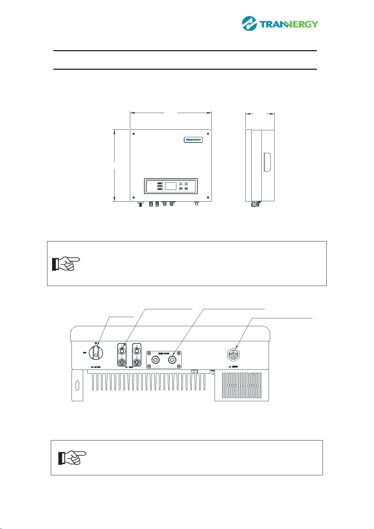
Figure 2-1 shows the outline dimensions of
TRB4000TL/5000TL/6000TL/8000TL/9000TL/010KTL
540
470
200
Figure 2-1 Outline dimensions of
TRB4000TL/5000TL/6000TL/8000TL/9000TL/010KTL
The AC output terminal is most length part at the bottom of inverter, so take
care of the AC output terminals, do not make it stand on the ground or other
materials
while moving or lifting the inverters otherwise will make terminal
damaged.
DC SWITCH DC INPUT TERMINALS COMMUNICATION TERMINALS
AC OUTPUT TERMINALS
Figure 2-2 Electrical Terminals of
TRB4000TL/5000TL/6000TL/8000TL/9000TL/010KTL
For safety reasons, the use of a DC switch is recommended. Between the
PV modules and the power modules may be mandatory in some
countries.

8User Manual
2.2. Electrical system design
Figure 2-3 wiring diagram of the whole
TRB4000TL/5000TL/6000TL/8000TL/9000TL/010KTL system.
Please refer to chapter 4 for the detail connecting and install methods.
2.3. The illustration of derating and limit the input power
To avoid inverter to be damaged by over temperature or over current.
Not output power when the temperature of power devices is over 85℃or the
ambient temperature is over 76℃.
Derate the output power linearly when the temperature of power devices is
between 81-85℃or the ambient temperature is between 70-76℃.
User Manual 9
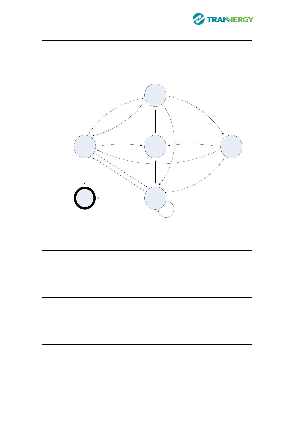
3. Operation mode illustration of the inverter
Our inverter has five operation modes during the whole work process; they are
wait, check, normal, fault and flash modes. Its detail illustration is shown by
Figure 3-1 below.
Shut Down
Wait Mode
Fault Mode
Flash Mode Normal Mode
Check Mode
Default:
Unrecoverable
Fault
Flash Event
Satisfy the power on condition
Have warning code
Flash Event
Flash Event
Flash Event
Check no errors
Have Fault event
Have warning events
or power off cmd
Have Fault event
Have Fault event
Recoberable fault cleared in 5s
Vpv<150Vdc
Vpv<150Vdc
Figure 3-1 State Machine of Inverter working mode
3.1. Wait mode
When the input power by solar panel is not enough to let the power module work,
it is at waiting mode. The inverter will wait until the input voltage is above
210Vdc and below 910Vdc, it turn to check mode.
3.2. Check mode
When the inverter is power on, it will check isolation, HCT device, GFCI device,
relay, fan, and soft start automatically in order. This can guarantee the inverter
work normally and turn to normal operation mode.
3.3. Normal mode
When the conditions above are satisfied, inverter will let the BOOST and inverter
module work and turn to normal generating power mode. It will change the solar
energy into electrical energy and fed it into grid based on advanced MPPT
technology in order to absorb solar energy in maximum extent possible. It will also

10 User Manual
calculate the generated energy per day/per month/per year automatically, save the
number in EEPROM and the number can be read from the HMI.
3.4. Fault mode
When there are fault during the inverter running, it will stop generating power and
turn to fault mode and display the fault information on LCD. Before do this, it will
store the generated power number into EEPROM automatically. Many not very
serious fault will be cleared after 5s automatically and retry to run. If the serious
fault generated, it will stay in the fault mode until the technical staff to solve the
problem.
3.5. Flash mode
Regardless the inverter running in which mode above, when there is the flash
command, it will turn into flash mode and rewrite the firmware in DSP flash.
3.6. Shut down
When the PV input voltage less than 150Vdc, the PV panel can’t provide energy
enough, so the inverter shut down automatically. When next day come, with the
irradiance increasing, it will run again smoothly if there are no fault occurrence.
User Manual 11
4. Installation and startup
4.1. Installation precaution
Warning!
Before installation and maintenance, AC and DC side doesn’t carry
electricity, but if DC side is just disconnected, capacitance still contains
electricity, so please
wait for at least 5 minutes to ensure the capacitors
completely release the energy and inverter is not electrified.
Note!
Inverters must be installed by qualified person.
Trannergy assures the product guarantee of the TRB series inverters during five
years after your purchase, if the installation site does not meet the instructions
described in this manual, it is out of warranty. The warranty is limited to the costs
of repair and/or replacement of the product by Trannergy only.
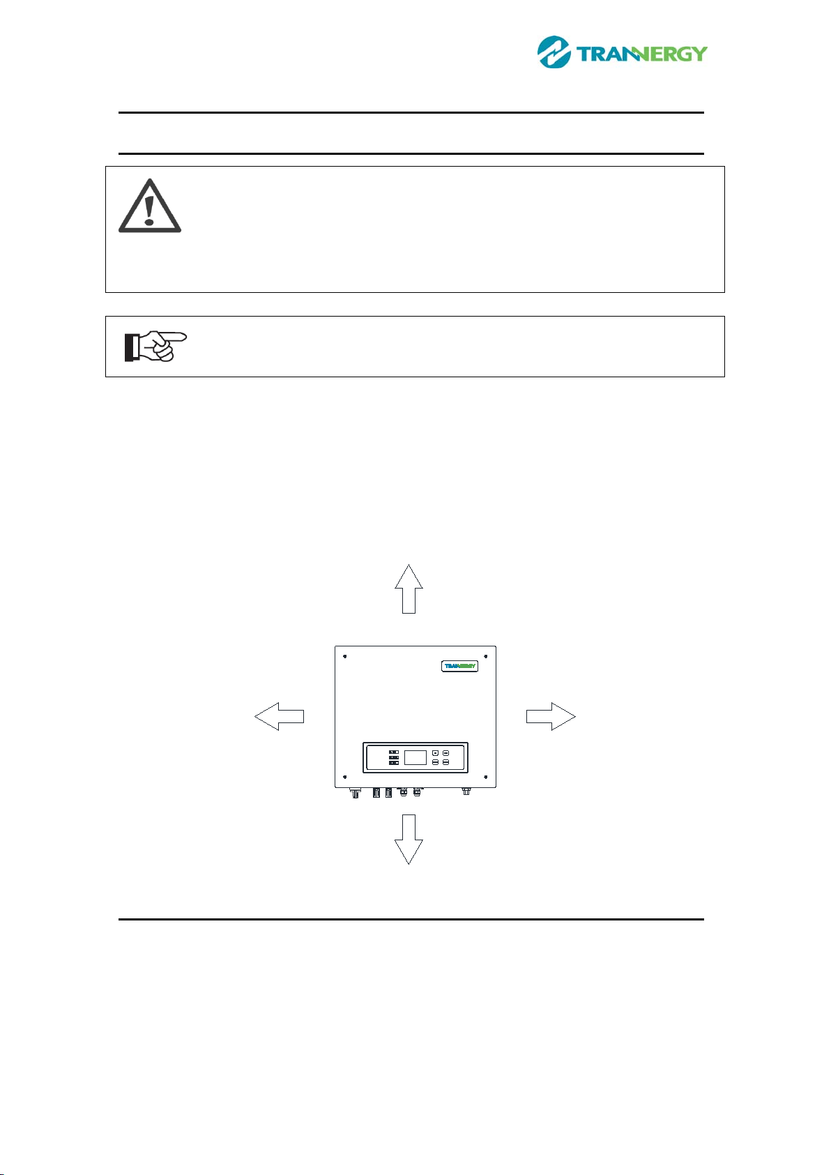
Ventilation is very important to cool the inverter. For outdoors application, the
inverter requires at least 300mm of clearance among the other units and 300mm of
the ground or the roof. See Figure 4-1:
300mm
300mm
300mm300mm
Figure 4-1 Distance required of Inverters
4.2. Install steps
Setp1: Drill six Ø10 holes in the wall according to the dimensions shows in Figure
4-2:
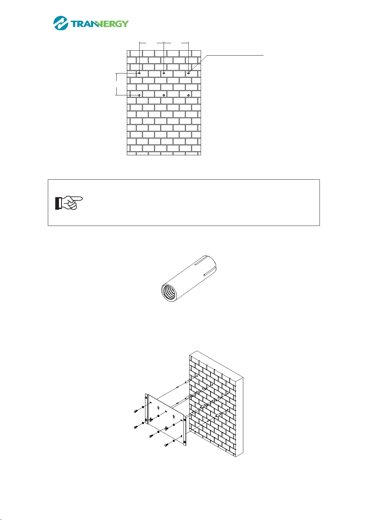
12 User Manual
200 200
180
6X
Φ10,45-50mm,Deep
Figure 4-2 Dimensions of drilling holes
Note!
Keep drilling vertical to the wall, and don’t shake when drilling to avoid
damage to the wall. It need repositioning and drilling holes if the hole with
much error.
Step2: Put the expansion pipe showing in Figure 4-3 into the hole vertically, use
hammer to tap the pipe into the wall completely.
Figure 4-3 Expansion tube
Step3: Put the mounting panel on the wall and twist the M8x50 screws into the
expansion tube to fix the mounting panel.
Figure 4-4 Install the mounting panel
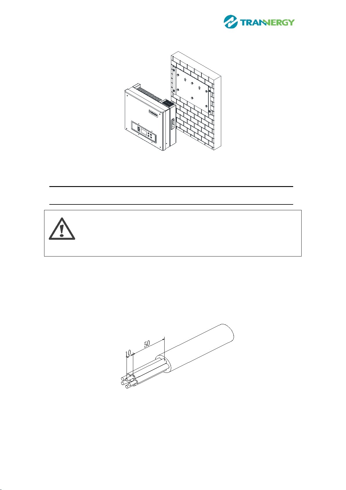
User Manual 13
Setp4: Hung the inverter on to the mounting panel:
Figure 4-5 Hung the inverter
4.3. Electrical connection
4.3.1. Connection to the grid (AC output)
Attention
Safeguard each inverter with an individual manual AC breaker in order that
inverter can be safely disconnected under load when installation &
maintenance.
Connection Procedure:
Step1: Switch off the AC breaker secure against being switched back on
inadvertently.
Step2: strip the cable as the following figure: (Recommended cable specification:
AWG 10 without crimping terminal; AWG 12 with crimping terminal)
Figure 4-6
Step3: AC female connector includes the following components:
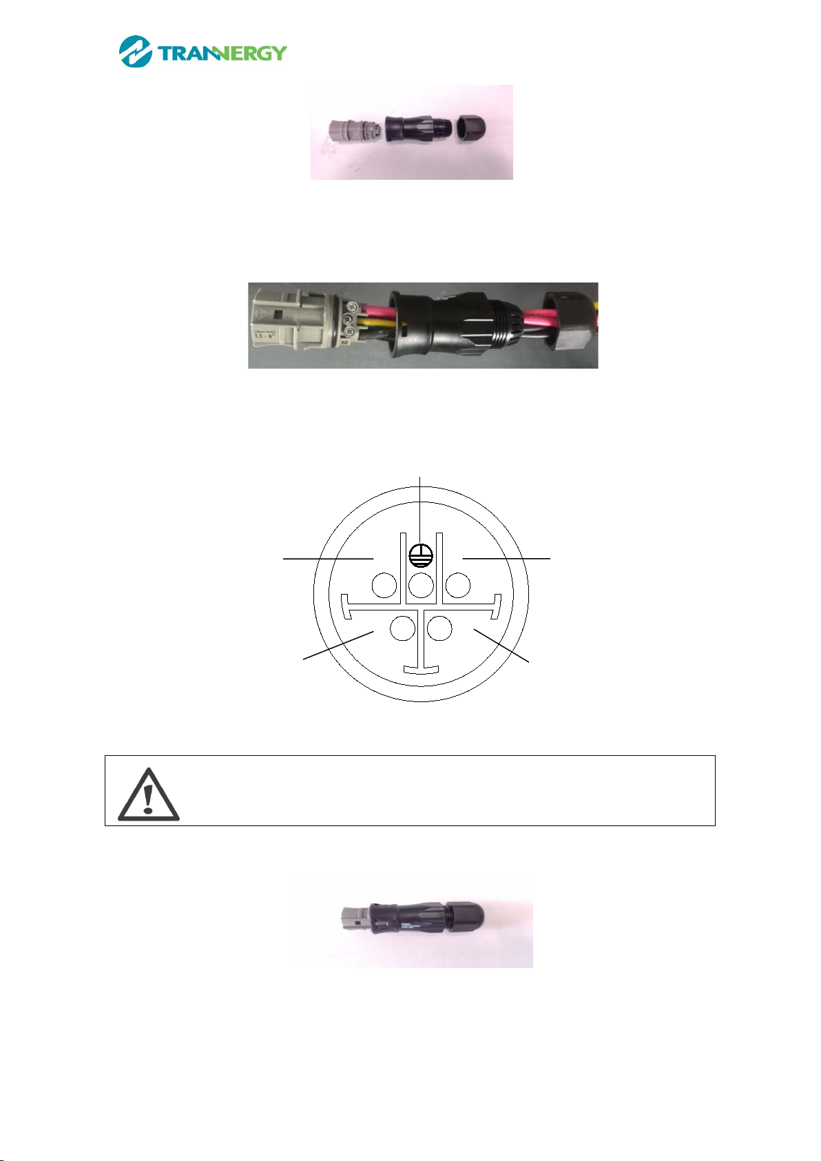
14 User Manual
Figure 4-7
Step4: Put the wires through Screw Cap, Adapter Body of the AC female
connector:
Figure 4-8
Step5: Connect the cables according to the following pictures:
N L
12
Figure 4-9
Attention!
Please ensure the corresponding relationship between polarities the core
cable and the hole of the terminal is correct.
Step6: Screw these components tightly after connecting the wires:
Figure 4-10
Step7: Connect AC female terminal to AC male terminal on inverter and then
screw them together.
R
T
S
N
PE

User Manual 15
4.3.2. Connection to PV generator (DC input)
Attention!
Safeguard each inverter with an individual manual DC breaker in order that
inverter can be safely disconnected under load when installation &
maintenance. The breaker should have certain capacity of over current and
over voltage. In addition, before cutting off the DC end connection. Please
cut off the AC end connection at first.
There are two MPPT trackers (A& B route) provided by the TRB4000TL /5000TL
/6000TL /8000TL /9000TL/010KTL and each MPPT tracker provides a pair of DC
input interface.
Attention!
Connectors must not be connected or disconnected under load!
Figure 4-11
Step1: Assembly Instruction for the male side and female side connector:
Strip cable .276 inches (9/32”) - (7mm) and be careful NOT to nick
conductors.
Figure 4-12
Amphenol specified strip tool can be used in this step. Adjust the striper
stopper and put the cable in corresponding notch to strip the length of 7mm.
See below figures.

16 User Manual
Figure 4-13
Insert striped cable into contact barrel and insure all conductor strands are
captured in the contact barrel and the conductors are visible in the contact
barrel observation hole. See below figures.
Figure 4-14
Crimp contact barrel by using the hex crimping die. See below figures
Figure 4-15
Amphenol specified crimping tool can be used in this step. Put the contact
barrel with striped cable in the corresponding crimping notch and crimp the
contact. See below figures.
Figure 4-16

User Manual 17
Insert contact cable assembly into back of male and female connector. A
“click” should be heard or felt when the contact cable assembly is seated
correctly. See below figures.
Figure 4-17
Wrest the cap by using the torque of 2.6~2.9NM.
Figure 4-18
Step2: Mate and separate Helios H4 connector:
After wrest the cap tightly, align the 2 half connectors and mate them together
by hand until a “click” is heard or felt.
Figure 4-19
When the separation of connector is necessary, use the Amphenol specified

18 User Manual
tool (Ring tool or wrench tool) to separate. And while using the ring tool or
wrench tool, please make sure the wedge side of the fingers faces the female
connector and push the tool down. Then separate the connector by hand. See
below figures.
Figure 4-20
DANGER!
DANGER to life due to potential fire or electric shock.
NEVER connect or disconnect the DC connectors under load.
4.4. Test run
Before turn on the inverter, please confirm:
a) Three phase five wires (R/S/T/N/PE) cable correctly connected to the inverter
AC side through AC circuit breaker;
b) The DC cable connected correctly to the inverter DC side through DC circuit
breaker, please be attention to the cable connected to the two string correctly
and it’s polarity;
c) The unused terminals are covered.
Turn on the inverter:
Step1: Close the DC and AC circuit breaker;
Step2: If the solar panels provide enough energy, the power module will work and
the LCD panel will be lit;
Step3: Then the inverter will turn into self-check mode and the LCD panel will
display the remaining time of connect simultaneously;
Step4: After the inverter turn into normal mode, it feed electrical energy into grid,
and LCD panel will display the generated electrical energy.
As long as the inverter works, it will automatically track the maximum power
point to absorb the maximum energy from solar. When night comes, the irradiance
is not strong enough to provide energy, the inverter will power off automatically.
When the next day comes, the input voltage reaches the start value, it will start
again automatically.
User Manual 19
5. Human Machine Interface
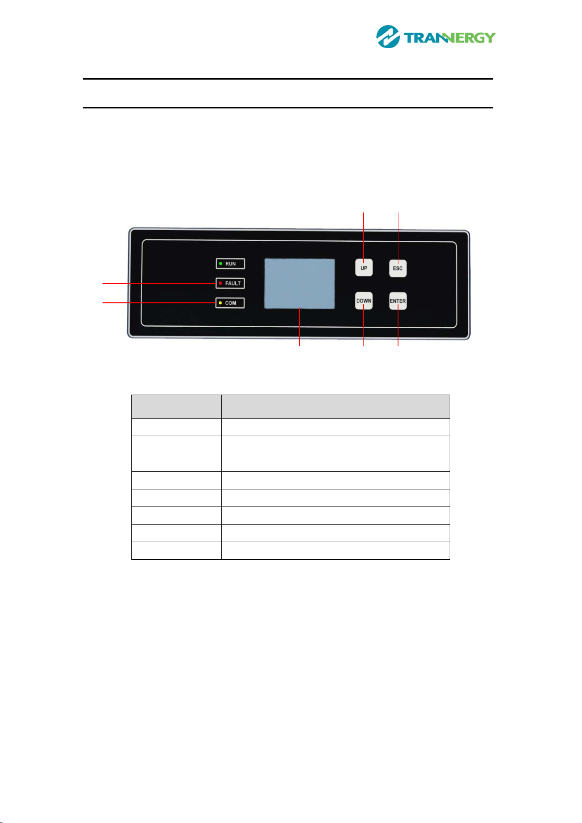
5.1. Control and Display Panel
Info provided here mainly includes LED display, LCD display, function keys and
display fault etc.
All function including parameter review, setting, and malfunction info etc can be
realized at this interface. It is showing as the follow (Figure 5-1).
Figure 5-1 Control and Display Panel
Object Description
A Working normally (Green LED)
B Fault (Red LED)
C Communication (Yellow LED)
D EXIT (Function key)
E Down (Function key)
F
OK (Function key)
G
LCD display
H Up (Function key)
TRB4000TL/5000TL/6000TL/8000TL/9000T/010KTL has 3 LEDs, 1 LCD and 4
function keys:
LEDs
Green LED: Working normally.
Yellow LED: Communication.
Red LED: Fault.
LCD
240×160 MONO LCD.
Function keys
A
B
C
H
D
E
F
G
This manual suits for next models
5
Table of contents
Other Trannergy Inverter manuals


Popular Inverter manuals by other brands


Fischer Panda
Fischer Panda Panda 4K PMS manual

Westerbeke
Westerbeke 10.0KW-60Hz Operator's manual

Northern Lights
Northern Lights Lugger ONL753W2 Operator's manual

Hoymiles
Hoymiles MI-1000NT Quick installation guide

SMA Solar Technology
SMA Solar Technology SUNNY BOY 1.5 operating manual

ABB
ABB REACT 2 Series product manual


