Amtex XP600 User manual

XP600/1100 INSTALLATION AND OPERATION MANUAL

2
XP SERIES INVERTERSXP SERIES INVERTERS
XP SERIES INVERTERS
DC/AC Sine Wave Inverters: 125 - 1100 Watts
Features
• True sine wave output
• Will power all types of loads
• State of the art switched mode design
• High MTBF>180,000 hours
• DC input options: 12V, 24V, 32V, 48V, 66V & 108V
• Frequency options: 50, 60 and 400HZ
• Output options: 100, 120, 230 VAC
• Overload, thermal and overvoltage protection
The XP series inverters provide the best regulated true sine wave
inverters on the market. Reliable, lightweight and with input
options from 12V to 110DC. With distortion of <2%, the XP
inverters are designed to provide smooth, clean, continuous AC
power without noise and spikes which could affect todays high
tech electronic equipment. They will also operate any type of
load, making them the ideal inverter in AC standby power
applications for telecommunications, industrial and other
commercial applications.
Power
XP
1 = 125W (not with 230V)
2 = 250W
6 = 600W
K = 1100W
0 = 100VAC
1 = 120VAC
3 = 230VAC
1 = 12VDC
2 = 24VDC
B = 32VDC
3 = 36VDC
4 = 48VDC
E = 66VDC
I = 110VDC
5 = 50HZ
6 = 60HZ
4 = 400HZ
Input 48VDC
Output 230VAC 50HZ, 600W
Power Code:
Out VAC code:
Input VDC code:
Frequency code:
eg. XP6 - 3 - 4 - 5 =
Model Selection
Frequency
Output VAC Input VDC
12VDC (10.5 - 16.5)
24VDC (21.0 - 33.0)
32VDC (28.0 - 44.0)
48VDC (42.5 - 62.0)
66VDC (58.0 - 91.0)
108VDC (95.0 - 149.0)
Sinusoidal
Typically 1.5%, maximum 2%
100V, 120V or 230VAC options
50HZ, 60HZ or 400HZ options
Regulation ±0.1%
125 to 1100 watts. Refer to table
Typically 2.2 times rated output
(except 125W units and 250W)
Typically 88% at rated load
Typically 0.1% maximum 0.5%
Typically 3% maximum 5%
-25°C to 40°C at rated power
5% to 95% non condensing
-200ft to 10,000ft operating
Less than 45dbA
Convection cooled 125 - 250W models.
Thermostatically controlled forced air
600 - 1100W models
EN55014
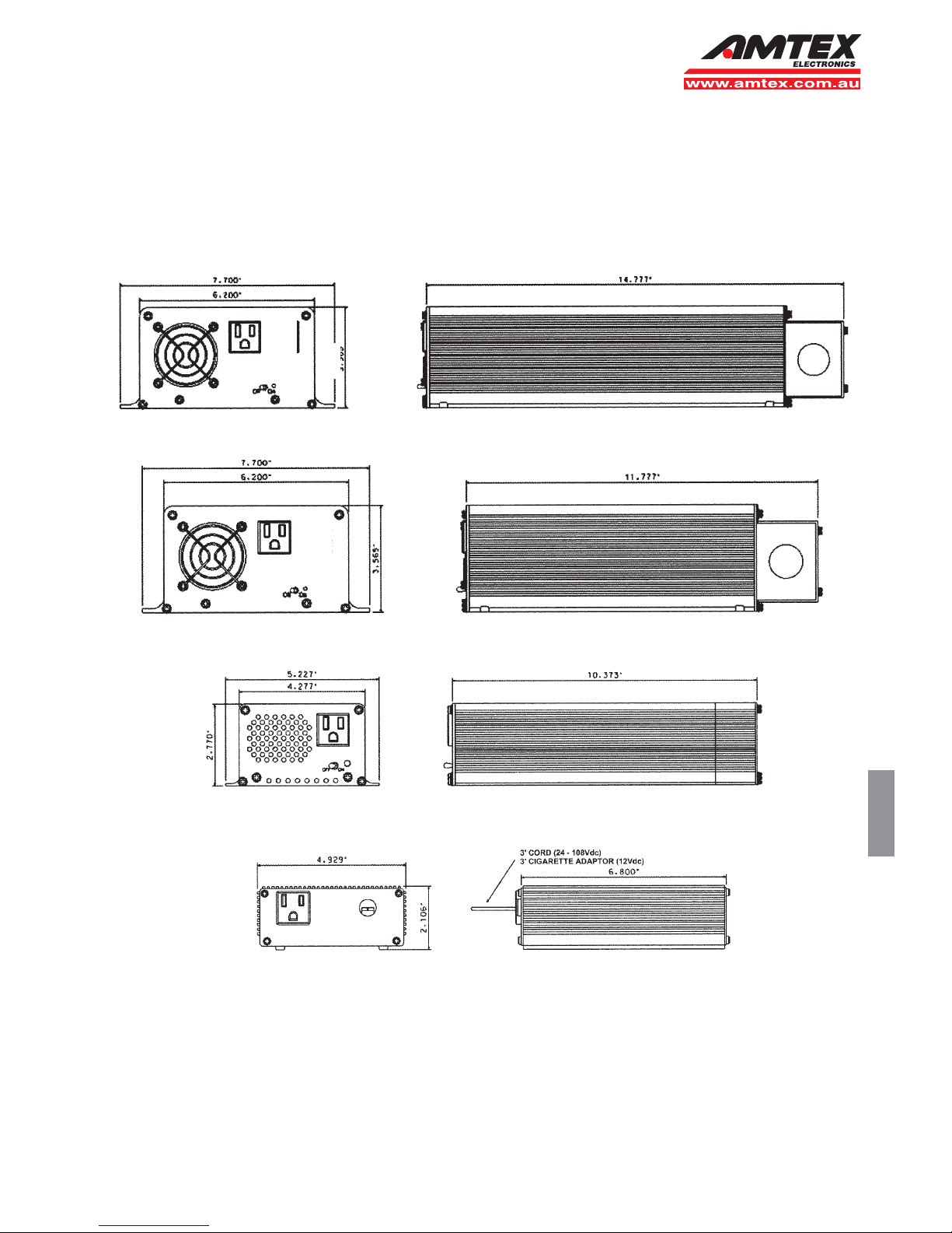
XP125: 118 x 51 x 172mm 0.9kg.
XP250: 265 x 70 x 135mm 3.0kg
XP600: 196 x 92 x 300mm 4.5kg.
XP1100: 196 x 92 x 375mm 4.5kg.
Shutdown at maximum input voltage
condition.
Shutdown at minimum input voltage
condition.
Shutdown at 105°C internal temperature,
warning buzzer at approximately 5°C
before shutdown.
Unit will shutdown in event of output
short.
P190BK050683 - converts IEC output
plug, to Australian plug.
INPUT VOLTAGE:
(Typical range)
AC WAVEFORM:
OUTPUT VOLTAGE:
HARMONIC DISTORTION:
FREQUENCY:
FREQUENCY REG:
OUTPUT POWER:
SURGE POWER:
EFFICIENCY:
REGULATION LINE:
REGULATION LOAD:
OPERATING TEMPERATURE:
HUMIDITY:
ALTITUDE:
AUDIBLE NOISE:
COOLING:
DIMENSIONS (WHD) & WEIGHT:
EMC:
PROTECTION (Automatically reset):
*
Specifications
*OVER VOLTAGE:
*UNDER VOLTAGE:
*THERMAL:
OUTPUT PROTECTION:
OUTPUT CABLE:

3
XP SERIES INVERTERSXP SERIES INVERTERS
XP SERIES INVERTERS
DC/AC Sine Wave Inverters: 125 - 1100 Watts
All dimensions in inches
XP1100
XP600
XP250
XP125
8

XP600/1100 INSTALLATION AND OPERATION MANUAL

XP600/1100 INSTALLATION AND OPERATION MANUAL
Page 5
Introduction 1.0
Standard Features 2.0
Installation 3.0
Operation 4.0
Appendix A
Appendix B
page 3
page 5
page 8
page 11
page 12
page 14
Table of Contents

XP600/1100 INSTALLATION AND OPERATION MANUAL
Page 6
Thank you for purchasing the finest sine-wave inverter in the power
conversion industry. The journey to excellence includes the
first affordable sine wave inverter, first modular inverter system, first
N+1 redundant inverter system, and the cleanest sine wave output
in the industry. We strives to manufacture products of the
highest possible quality, and is dedicated to 100% customer
satisfaction. Proudly built in the USA with American parts,
Committed to TL 9000 standards and beyond, adding people and
procedures continually to further improve quality and customer
service.
XP series inverters provide the cleanest, best regulated sine wave
output over the widest DC input of any inverter on the market today.
They are extremely low in Total Distortion; specified to 2%, and
typically better than 1.5%. Total Harmonic Distortion is typically 0.8 to
0.9%. Remaining distortion is a result of residual switching noise,
which amounts to a very clean 25 KHZ sine wave superimposed on
the fundamental output. No significant harmonics of 25 KHZ exist.
This spectral purity will exist over the inverter's entire operating
envelope, including non-linear and reactive loads. As long as peak
output current remains less than 300% of rated current, total harmonic
distortion will remain within the 2% spec. Peak current capability of the
inverter is key to understanding it's operational envelope. As long as
the inverter is supplying less than this amount, it will function properly
and operate virtually any load.
Many inverters are rated in Volt-Amps (VA), as opposed to Watts.
This is in an attempt to make an inverter or UPS (Uninterruptible
Power Supply) appear larger than it really is. The only fair way to
.
.
Introduction
1.0

XP600/1100 INSTALLATION AND OPERATION MANUAL
Page 7
specify these products is in Watts (W), which is power the inverter
can actually deliver. If the XP inverters were specified in VA, Our
1100 Watt inverter could be rated at 1375 VA at .8 power factor,
1570 VA @ .7 pf, or an incredible 2200 VA @ .5 pf. It is confusing to
specify a product in VA, because the power factor must also be
specified. XP-Series inverters can output their full rated
oo
power continuously at 40 C
The inverter can maintain a spectrally pure output with any load, due
to a specially designed non-linear control loop in the primary DC to
DC converter. This circuitry is one of three circuits which protect the
inverter from any overload condition.
.
.
.XP-600 and XP-1100
These inverters can supply twice their rated output power for 3
seconds, in order to start motors or supply in-rush currents to
electronic loads. If output power is exceeded for greater than 3
seconds, output voltage is reduced to a level which will provide
the inverter’s rated power to the load by clipping tops of the
waveform. The inverter can operate safely in this mode indefinitely.
Should the overload condition clear, the inverter will again provide
the cleanest Sine Wave in the industry. This over-current circuitry
insures maximum peak current does not exceed 300% of rated
RMS current. Should this number be exceeded, it will again reduce
output voltage as required to maintain that limit. Again, the inverter
can operate in this mode indefinitely, so that when the overload
clears, output voltage is automatically restored. The third protection
mechanism is short circuit. If the inverter exceeds it’s peak current
(Ip) capacity for a prolonged period, it will shut off automatically. The
period of time required to shut off changes with the degree of
overload. A high overload shuts off in one second. A slight overload
may require several seconds. This typically requires a .5 ohm load
per 1000 Watts, for several seconds. This guarantees the inverter is
disabled, in the event that the user attempts to clear the short
without first shutting off the inverter. The inverter in fact, acts as an
extremely high performance circuit breaker. The short circuit and
overload circuitry responds much faster than any normal fuse or
breaker, so no external current limiting devices are necessary.
XP-Series inverters can output their full rated power
continuously at 40o C.The inverter is derated 20% of its

XP600/1100 INSTALLATION AND OPERATION MANUAL
Page 8
full power for every 10 degrees C over 40 degress C. IE; 80% of
normal capacity at 50 degrees C.. . . etc. .
DC INPUTS:
REMOTE ON/OFF:
AC OUTPUTS:
* XP-1100, XP-600 230 VAC
COOLING:
DC POWER ON LED:
LOW BATT / THERM BUZZER:
Positive (+) and Negative (-) input terminals are 5/16"
studs with brass hardware. They are accessed under the Rear
Cover. Use Appendix “A” to choose the appropriate gauge wire for
your specific model.
provides the User with a remote method to turn
the inverter on and off. “REMOTE” connection is on the barrier
terminal strip located under the Rear Cover.
All models (*except 230 VAC output) have two,
NEMA -15 outlets (standard wall receptacle), located on the Front
Panel. Additionally; may be hard-wired to appliance / load using
connections on the barrier terminal strip, located under Rear Cover.
, inverters have an IEC-320 receptacle
located on the Front Plate.
is provided by a thermostatically controlled brushless fan
located on the Front Panel.
located on the front panel, will be "ON" when
inverter is powered up, and DC power is available.
produces an audible alarm if DC
input voltage falls to a level within 2% to 4% of the low limit of
inverter, or, if there is an over temperature condition.
.
.
.
.
.
.
Standard Features
2.0

XP600/1100 INSTALLATION AND OPERATION MANUAL
Page 9
located on front panel; turns the inverter on and
off.
If input voltage to the inverter
exceeds set limits, the inverter will immediately and without warning
shut off. When input voltage returns to normal range, the inverter will
immediately restart. Since high over voltages tend to have very fast
edges, the inverter must shut down quickly to protect itself. This kind
of fault usually occurs if the battery is suddenly disconnected from
the system and the battery charger continues to supply current.
When battery voltage falls to
within 2% to 4% of low line voltage, the LOW BATT / THERM buzzer
will sound. If the condition continues without reducing load to the
inverter or adding charge to the battery, the inverter will shut off.
When voltage rises to approximately 95% of nominal battery
voltage, the inverter will turn back on and the alarm condition will
clear. The inverter can be manually reset by cycling the on/off
switch. This will reset the protection circuit and turn the inverter
on at any voltage above minimum voltage.
The inverter is also
protected against overheating. It will provide its full rated output up
to the temperature listed in the specification sheet. If it is subjected
to higher ambient temperatures or air circulation is blocked, the
inverter may overheat. If the LOWBATT/ THERM buzzer sounds,
immediate action is required or the inverter will shut down. Either
reduce load, or provide more cooling in the immediate environment.
If no action is taken, the inverter will likely shut down within 2
minutes. When the inverter shuts down, the alarm condition will
persist and the cooling fan will continue to run. Since the inverter
has eliminated its load, it will cool fairly quickly. It will automatically
restart when it has cooled sufficiently, and the LOW BATT/THERM
alarm will clear. “105 C internal temperature. Warning buzz 5 C
before shut off”.
ON/OFF SWITCH:
OVER VOLTAGE PROTECTION:
UNDER VOLTAGE PROTECTION:
OVER TEMPERATURE PROTECTION:
OVERPOWER, SHORT CIRCUIT PROTECTION:
.
.
.
The inverter has
three levels of overpower protection. The first limits peak
instantaneous current. The second system limits absolute power
coming from the module. Both of these circuits act to reduce output

XP600/1100 INSTALLATION AND OPERATION MANUAL
Page 10
voltage as required, to limit current to a safe level. The overpower
protection circuit will recover instantly when the overpower condition
clears. The third, is short circuit protection. If the over current
condition is so severe that it causes output voltage to collapse to 1
Vp for more than 1 second, the inverter will shut down and not auto-
matically restart. This requires the user to clear the short circuit
safely, and guarantee that hazardous voltage will not come back on
line until desired. To reset the inverter from this condition, cycle
power switch “OFF” then “ON” again. .

XP600/1100 INSTALLATION AND OPERATION MANUAL
CAUTION:
WARNING:
WARNING:
CAUTION:
It is essential to read and understand all Warnings,
Cautions, and Notes before any connections are made to the Unit
or System. If further assistance is needed call (817)595-4969 and
ask for Customer Service.
The inverter is designed to operate from a Battery.
Performance cannot be guaranteed, and damage can result when a
charger or power supply is used without a battery in the circuit.
The AC neutral lead is internally bonded to chassis;
chassis must be bonded to earth ground through the external
ground connector that is located on the unit. The Negative or Positive
terminal of the battery (DC Source) must be bonded to earth ground;
it is recommended that it be to the same earth ground used for AC
ground. Refer to the figure below for wiring illustration.
Before any connections are made to the Unit or System,
be sure to disconnect the battery terminals. Always disconnect the
grounded battery terminal first. When re-connecting, connect
ungrounded terminal first, and grounded terminal last.
.
.
.
.
Installation
3.0
Battery
Inverter
+
--
+
(A)
(B)
A) Positive earth ground
B) Negative Earth Ground
*Note: Only “A” or “B”
NOT BOTH.
Page 11

XP600/1100 INSTALLATION AND OPERATION MANUAL
CAUTION:
CAUTION:
INSTALLATION (Location)
1.
2.
3.
INSTALLATION (Wiring)
Polarity of leads is critical to avoid damage to the unit or
system. Check batteries and battery cables for correct polarity and
voltage.
Observe all National and Local Electric Codes when
connecting AC Power Connections.
Mounting location is critical to performance and life span of the
inverter. Heat and Moisture are the two worst enemies of any
electronic device. Therefore, when choosing a mounting location,
consider the following requirements listed in order of importance:
Inverter must be sheltered from the elements. Select a clean, dry
location.
Inverter requires adequate ventilation for cooling. With proper
cooling, the inverter will operate efficiently and meet its published
ratings. All models can be mounted in several positions. Best
position, with fan down. Second best, horizontal. Third, vertical
with fan up. Least preferred, upside down.
Inverter should be mounted as close to the battery as possible.
Shorter wire has less resistance, which translates to increased
efficiencies.
An in line fuse is recommended, to protect the battery and wiring to
the inverter. This fuse should be located very close to the battery
positive (+) terminal. To select appropriate size fuse, consult the
"Rated and Peak Current" table in appendix "B".
charger and inverter are off.
.
.
.
.
.
.
.
.
.
XP-600 and XP-1100: Positive (+) and Negative (-) input terminals
are 5/16" studs with brass hardware. They are provided under the
Rear Cover. Use Appendix “A” to choose the appropriate gauge wire
for your specific model and distance from the battery.
1. Disconnect the grounded (-) terminal of battery and make sure the
Page 12

XP600/1100 INSTALLATION AND OPERATION MANUAL
Make DC input connections to the inverter as illustrated in
Appendix “C”.
(Optional) Using 12-18 AWG wire, make Remote On/Off
connection from the Rear Panel terminal labeled “REMOTE” to
one pole of a small toggle switch. Then from the other pole of
toggle switch, make a connection to battery negative (-).
Make sure the toggle switch is off.
Note: in order for the Remote On/Off switch to operate inverter,
On/Off switch on the Front Panel must be off.
If the Appliance / Load will be hard wired to the inverter instead of,
or in addition to, using the outlets provided on the Front Panel, see
Appendix “C”.
2.
3.
4.
5.
.
.
.
.
.
Page 13

XP600/1100 INSTALLATION AND OPERATION MANUAL
TURN ON INVERTER:
XP-600 and XP-1100:
Note:
TURN ON APPLIANCE/LOAD:
1.
2.
3.
Note:
Turn inverter on using Toggle Switch on
Front Panel, or the "REMOTE" switch if installed. LED next to the
switch will illuminate, indicating the inverter is operational.
If using "REMOTE" switch, the Front Panel Switch must be
off. (If either switch is "on", the inverter will turn on. Both switches
must be off for the inverter to turn off.)
Check Input Power Requirements of the appliance. Make sure
that it is less than Rated Output Power of the inverter. If more than
one appliance will be run simultaneously, the sum of their Input
Power Requirements must be less than Rated Output Power of the
inverter.
If Appliance/Load has been hard wired to the barrier terminal strip
as illustrated in Appendix "B", then turn appliance on. Otherwise;
Plug the appliance into the provided receptacle on Front Panel,
then turn appliance on.
It is recommend that the inverter be turned ON before the
appliance/load.
.
.
.
.
.
.
.
Operation
4.0
Page 14

XP600/1100 INSTALLATION AND OPERATION MANUAL
APPENDIX A
XP-600 / 12VDC 13.8 VDC 10.4 / 10.6 VDC 16.5 VDC 58.8 A 66.6 A
XP-600 / 24VDC 27.6 VDC 19 / 21 VDC 33 VDC 29.4 A 33.6 A
XP-600 / 48VDC 55.2 VDC 41.5 / 42.5 VDC 62 VDC 14.7 A 16.6 A
XP-600 / 66VDC 75.9 VDC 57.5 / 58.5 VDC 91 VDC 10.7 A 12.1 A
XP-600 / 108VDC 124.0 VDC 94 / 95 VDC 149 VDC 6.5 A 7.4 A
MODEL
NORMAL
VDC
MINIMUM VDC
CUT-OFF / ALARM
MAXIMUM
VDC
RATED
CURRENT
PEAK
CURRENT
XP-600 / 12VDC
MODEL
Input Power Requirements:
Recommended Input Wire Sizes (For Variable Distances from the Battery):
4 AWG
LESS THAN 5’
0 AWG
LESS THAN 10’
0 AWG
LESS THAN 15’
00 AWG
LESS THAN 20’
XP-600 / 24VDC 10 AWG 6 AWG 4 AWG 4 AWG
XP-600 / 48VDC 16 AWG 12 AWG 10 AWG 10 AWG
XP-600 / 66VDC 18 AWG 16 AWG 14 AWG 12 AWG
XP-600 / 108VDC 18 AWG 18 AWG 18 AWG 16 AWG
Note: The table specifies standard wire sizes (not smaller than 18 AWG) that will provide less than a
2% voltage drop at Low-line Input voltage and Rated Output Power.
XP-1100 / 12VDC 13.8 VDC 10.4 / 10.6 VDC 16.5 VDC 107.8 A 122.1 A
XP-1100 / 24VDC 27.6 VDC 19 / 21 VDC 33 VDC 53.9 A 61.6 A
XP-1100 / 48VDC 55.2 VDC 41.5 / 42.5 VDC 62 VDC 27 A 30.5 A
XP-1100 / 66VDC 75.9 VDC 57.5 / 58.5 VDC 91 VDC 19.6 A 22.1 A
XP-1100 / 108VDC 124.0 VDC 94 / 95 VDC 149 VDC 12 A 13.6 A
XP-1100 / 12VDC 0 AWG 00 AWG 0000 AWG 0000 AWG
XP-1100 / 24VDC 6 AWG 4 AWG 2 AWG 0 AWG
XP-1100 / 48VDC 12 AWG 10 AWG 8 AWG 6 AWG
XP-1100 / 66VDC 16 AWG 12 AWG 10 AWG 10 AWG
XP-1100 / 108VDC 18 AWG 16 AWG 14 AWG 14 AWG
Page 15
See page 13 for Mechanical dimensions and mounting hole locations.

XP600/1100 INSTALLATION AND OPERATION MANUAL
APPENDIX A
Page 16
0
7.690
0
3.565
0
.780
1.280
8.897
9.342
12.100
0
.375
7.315
7.690
.281
0.125 DIA.
4PLCS
0
12.100
0
3.565
0
7.690
0
3.565
0
.375
7.315
7.690
0
.780
1.280
11.842
12.345
15.050
.281
0.125 DIA.
4 PLCS
0
15.050
0
3.565
XP600
XP1100
TOP
FRONT SIDE
FRONT SIDE
TOP

XP600/1100 INSTALLATION AND OPERATION MANUAL
APPENDIX B
Page 17
Note: Use Rated Current and voltage in Appendix "A" to select an
appropriate Toggle Switch or Relay for your specific model inverter.
XP-600 and XP-1100 with DC Toggle Switch:
XP-600 and XP-1100 with DC Relay:
INSTALLATION .
CAUTION: Be sure to disconnect all DC power to installation wiring.
Be sure to disconnect batteries and chargers. Make all connections
to the inverter BEFORE connecting DC leads to the battery. .
Inverter
Battery
DC Toggle Switch
(See Appendix A)
+
-
+
-
Inverter
Battery
+
-
+
-
Relay Coil
Relay
Normally Open
Contacts
DC Toggle Switch
(Low Current)
XP-600 and XP-1100 Rear View with access cover removed
(AC/DC Connections):
BAT -
BAT +
GROUND
NEUTRAL
LINE
REMOTE

Page 13 of 17
ADDENDUM FOR X20, X27, & X28 OPTIONS (XP600 AND XP1100)
GENERAL
The X20, X27, and X28 option provides for an alarm contact OR an AC transfer switch on
EXELTECH XP Series inverters. The alarm relay monitors the inverter’s AC output and
will energize the alarm contact when the inverter fails to produce AC.
The AC transfer switch can be configured in two ways (via jumpers)
1. Inverter as the primary source of AC power.
2. Utility as primary source of AC power.
CAUTION: “ ANY OPTION THAT USES TRANSFER SWITCH IS NOT
AUTHORIZED FOR USE IN LAND MOBILE APPLICATIONS ”
NOTE: All secondary AC power sources other than the inverter will be referred to as
utility. A secondary source of AC power includes utility, “shore power”, generator, etc.
When the primary source of AC power fails, the transfer switch “switches” to its
secondary source of AC power in 50ms or less. When the primary source of power is
present again (turns back on), the transfer switch “switches” back to the primary source
of power in 50ms or less.

Page 14 of 17
BAT+ & BAT- 5/16 in. stud mount for battery input, be careful to observe proper
polarity.
CHAS Chassis or earth ground (green wire) should be connected here.
NEUT Neutral or return line (white wire) of the AC output.
INVOUT Hot or AC output of the inverter (black wire).
NO Normally open contact of the relay. When the “COIL” terminal is
energized, this contact is connected to “C” (common terminal).
When the “COIL” terminal is not energized, this contact is not
connected to “C” (common terminal).
C The common terminal of the relay.
NC Normally closed contact of the relay. When the “COIL” terminal is
energized, this contact is not connected to “C” (common terminal).
When the “COIL” terminal is not energized, this contact is
connected to “C” (common terminal).
RMT Remote terminal. Applying battery negative to this terminal will turn
the inverter ON. Use a switch connected to battery negative and
the remote terminal to turn on the unit remotely. This terminal has
no significant current demand.
UTIL When utility AC power is connected to the “NO” terminal, this
terminal can be used with a jumper to energize the “COIL” when
utility is on.
COIL The coil contact of the relay. This must be connected to the INV
terminal to function as an alarm and can have either UTIL or INV
jumpered to it to function in a transfer switch.
INV A low current output of the inverter voltage to drive the relay.
INSTALLATION
CAUTION: Be sure to disconnect all DC power to the installation wiring. Be sure to
disconnect both the batteries and the chargers which may be connected. Make all
connections to the inverter BEFORE connecting DC power to the battery.

Page 15 of 17
ALARM CONTACT CONFIGURATION
-X27 OPTION
The alarm contact is configured via jumpers on a removable terminal plug on the back
of the inverter
1. Remove the terminal plug from the inverter by hand or with needle-nose pliers. On
the underside of the plug are screw terminals to set connections. (The terminal plug
can take up to 12GA wire.)
2. Insert a jumper between COIL and INV. (see drawing) When the inverter is on, the
alarm relay will energize.
If it is desired to sense the AC voltage elsewhere in the system such as after a circuit
breaker, remove the jumper between COIL and INV and connect the AC hot from the
point you want to sense to the COIL contact.
3. Connect alarm signal input wire (supplied by operator) to “C” (common) contact.
Connect alarm signal output wire to either NO (normally open) or NC (normally close)
contacts.
OPERATION
When Battery voltage is available to the inverter, the inverter will turn “on” when the
front panel switch is turned “on” OR when the RMT (remote) terminal is connected to
battery negative. When the inverter comes “on” the alarm relay will energize and there
will be continuity between the NC (normally open) and “C” (common) contacts of the
relay terminals.
Inverter AC output will be available from the NEMA 15 terminals in the front (plug) and
at the output terminals in the rear of the inverter (terminals marked INVOUT for AC hot,
NEUTRAL for AC return, and CHASSIS for ground). To shut “off” the inverter the front
switch must be turned “off” AND the remote switch must be in the “off” position.
This manual suits for next models
1
Table of contents
Popular Inverter manuals by other brands

Motomaster
Motomaster ELIMINATOR 299-5299-0 owner's manual

Energy
Energy zeroCO2 large RHI-3P5K-HVES-5G Operation manual

Mitsubishi Electric
Mitsubishi Electric FR-S520E-0.1K instruction manual

Senci
Senci AP2000i user guide

Chelion
Chelion iHome-INV3K-6K-L1h02 user manual

Xantrex
Xantrex PROwatt SW 2000i owner's guide