9
GM3500Xi
10
11
12
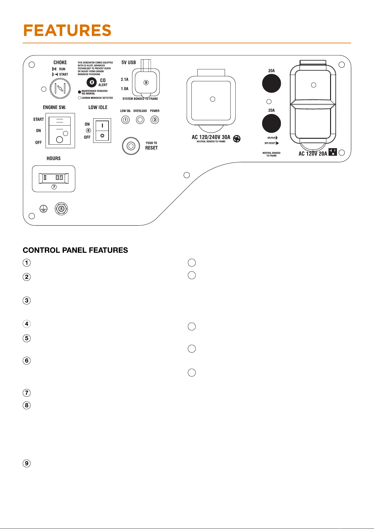
USB Duplex: 5V DC that come in 1 amps and
2.1 amps.
AC Protector: If the generator is overload, the AC
protector will trip to block current.
Ground Terminal: The ground terminal is used to
externally ground the generator.
Hours: Total time of generator use.
CO Alarm LED: Flashing red light: dangerous
levels of carbon monoxide gas have built up leave
immediately until area has aired out. Move
generator to well-ventilated area before operation.
Flashing yellow light: carbon monoxide sensor
malfunction. Sensor needs service.
120-Volt, 20-Amp Duplex Outlet : The outlet is
capable of carrying a maximum of 20 amps.
120-Volt, 30-Amp Outlet : The outlet is capable of
carrying a maximum of 30 amps.
2
4
10
13
12
11
14
15
13
14
Main SW.: Manage battery power and shutdown.
Overload Alarm: Indicates that the generator
is overloaded.
Low Oil Alarm: Indicates low oil level.
Efficiency Mode Switch: When turned to the ON
position, the engine will sense the load needed and
run at a slower RPM to save fuel.
Parallel Connectors:To increase AC power output,
the connector sockets are used to connect the two
same type generator with special paralleling cords.
The connector sockets is only used to the
communication between the inverters, they can not
used for AC power output.
The special paralleling cords shall be purchase
separately, and they shall be approved by
certification body.
Reset Breaker: If the is overloaded, the generator
reset breaker will trip. The engine will continue to
run, but there will be no output from the inverter
Unplug the devices and reduce the load. Push in the
reset breaker to reset it.
Power Alarm: Indicates the generator is
ready to be used.
Choke : Pull out to start, press Run.
15