Solar PST-250 Aero Termo Specification sheet

Domestic Hot Water Heat Pump
Operation and Installation Manual
ENGLISH
02/07/2012

2
Read this manual carefully before starting up the unit.
Retain this manual for future reference.
Before operating the unit, make sure the installation has been
carried out correctly by a professional dealer. If you feel unsure
about operation, contact your dealer for ad ice and
information.

3
TABLE OF CONTENT
INTRODUCTION .............................................................................................................................................. 4
This manual ................................................................................................................................................ 4
The unit ...................................................................................................................................................... 4
SAFETY INSTRUCTIONS ................................................................................................................................... 5
ITEMS INSIDE PRODUCT BOX ......................................................................................................................... 7
OVERVIEW OF THE UNIT ................................................................................................................................ 8
Parts and descriptions. ............................................................................................................................... 8
Dimensions ................................................................................................................................................ 9
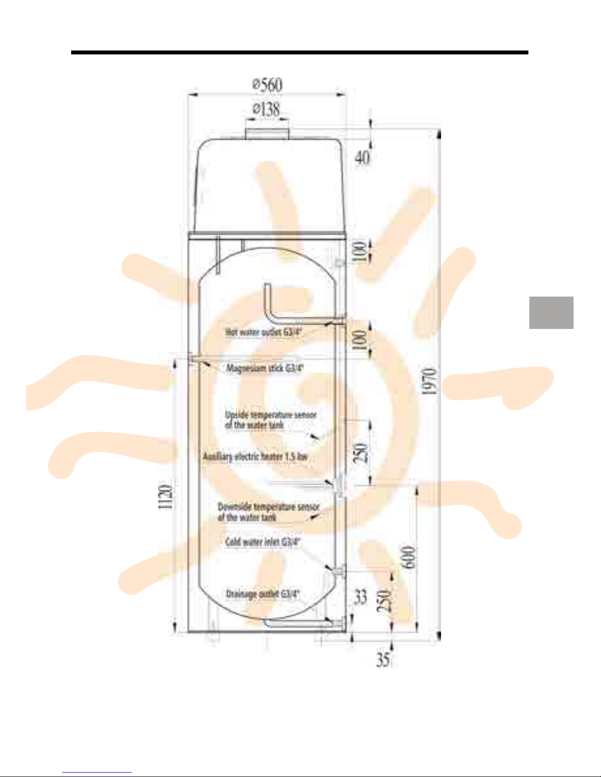
Water tank dimensions ............................................................................................................................ 10
How to replace the magnesium stick. ...................................................................................................... 11
Schematic o er iew of the water and refrigeration circuit ...................................................................... 11
INSTALLATION .............................................................................................................................................. 12
Installation o er iew ................................................................................................................................ 12
Required ser ice space............................................................................................................................. 13
Choose the suitable unit .......................................................................................................................... 14
Transportation ......................................................................................................................................... 14
Installation positions ................................................................................................................................ 15
Water loop connection ............................................................................................................................ 17
Wire connection ....................................................................................................................................... 17
Trial running ............................................................................................................................................. 17
OPERATING THE UNIT .................................................................................................................................. 18
Features and functions............................................................................................................................. 18
User interface .......................................................................................................................................... 19
Operations ............................................................................................................................................... 19
LCD icons .................................................................................................................................................. 22
PARAMETER CHECKING AND ADUSTMENT .................................................................................................. 23
Parameter list ........................................................................................................................................... 23
Malfunctioning of the unit and error codes ............................................................................................. 24
MAINTENANCE ............................................................................................................................................. 25
Maintenance acti ities ............................................................................................................................. 25
TROUBLESHOOTING ..................................................................................................................................... 25
ENVIRONMENTAL INFORMATION ................................................................................................................ 25
DISPOSAL REQUIREMENTS ........................................................................................................................... 26
WIRING DIAGRAM ....................................................................................................................................... 27
TECHNICAL SPECIFICATION .......................................................................................................................... 28
TEMPERATURE SENSOR R-T CONVERSION TABLE ........................................................................................ 29
WARRANTY .................................................................................................................................................. 30
EN

4
INTRODUCTION
This manual
This manual includes the necessary information about the unit. Please read this manual carefully before
you use and maintain the unit.
The unit
The hot water heat pump is one of the most economical systems to heat the water for family domestic
use.
Using free renewable energy from the air, the unit is highly efficient with low running costs. Its efficiency
can be up to 3 ~ 4 times more than con entional gas boilers or electrical heaters.
•Waste Heat recovery
Units can be installed near the kitchen, in the boiler-room or the garage, basically in e ery room
which has a large number of waste-heat so that the unit has the higher energy efficiency e en
with ery low outside temperatures during the winter.
•Hot water and dehumidification
Units can be placed in the laundry room or clothing room. When it produces hot water it lowers
the temperature and dehumidifies the room as well. The ad antages can be experienced
particularly in the humid season.
•Stora e room coolin
Units can be placed in the storage room as the low temperature keeps the food fresh.
•Hot water and fresh air ventilation
Units can be placed in the garage, gym, basement etc. When it produces hot water, it cools the
room and supplies fresh air.
•Compatible with different ener y sources
Units can be compatible with solar panels, external heat pumps, boilers or other different
energy sources.
•Ecolo ical and Economical Heatin
Units are the most efficient and economical alternati e to both fossil fuel boilers and heating
systems.
By making use of the renewable source in the air, it consumes much less energy without direct
CO2 emission.
•Compact desi n
Units are especially designed for offering sanitary hot water for family use. It’s extremely
compact structure and elegant design are suitable for indoor installation.
•Multiple Functions
The special design of the air inlet and outlet makes the unit suitable for arious ways of
connections. With different ways of installation, the unit can work as just a heat pump but also
as a fresh air blower, a dehumidifier, or an energy reco ery de ice.
•Other features
oStainless steel tank and a magnesium stick assure the durability of components and
the tank.
oHighly efficient compressor with the R134a refrigerant.
oElectrical element a ailable in the unit as a back-up, assuring constant hot water
e en in extreme cold winters.

5
SAFETY INSTRUCTIONS
To pre ent injury to the user, other people, or property damage, the following instructions must be
followed. Incorrect operation due to ignoring of instructions may cause harm or damage.
Install the unit only when it complies with local regulations, by-laws and standards. Check the main oltage
and frequency. This unit is only suitable for earthed sockets, connection oltage 220 – 240 V ~ / 50Hz.
The following safety precautions should always be taken into account:
•Be sure to read the following WARNING before installing the unit.
•Be sure to obser e the cautions specified here as they include important items related to
safety.
•After reading these instructions, be sure to keep it in a handy place for future reference.
WARNING
Do not install the unit yourself.
Incorrect installation could cause injury due to fire, electric shock, the unit falling or leakage of water.
Consult the dealer from whom you purchased the unit or a specialized installer.
Install the unit securely in a place.
When insufficiently installed, the unit could fall causing injury. The minimum support weight of
20g/mm² of the installation place is required. When installing the unit in a small room, please take
measures (like sufficient entilation) to pre ent the asphyxia caused by the leakage of refrigerant.
Use the specified electrical wires and attach the wires firmly to the terminal board (connection in such a
way that the stress of the wires is not applied to the sections).
Incorrect connection and fixing could cause a fire.
Be sure to use the provided or specified parts for the installation work.
The use of defecti e parts could cause an injury due to possible fire, electric shocks, the unit falling etc.
Perform the installation securely and please refer to the installation instructions.
Incorrect installation could cause an injury due to possible fire, electric shocks, the unit falling, leakage of
water etc.
Perform electrical work accordin to the installation manual and be sure to use a dedicated section,
fused with 16A.
If the capacity of the power circuit is insufficient or there is an incomplete electrical circuit, it could result
in a fire or an electric shock.
The unit must always have an earthed connection.
If the power supply is not earthed, you may not connect the unit.
Never use an extension cable to connect the unit to the electric power supply.
If there is no suitable, earthed wall socket a ailable, ha e one installed by a recognized electrician.
EN

6
Do not move/repair the unit yourself.
If the supply cord is damaged, it must be replaced by the manufacturer or its ser ice agent or a similarly
qualified person in order to a oid a hazard. Improper mo ement or repair on the unit could lead to water
leakage, electrical shock, injury or fire.
The unit is no intended for use by children.
This appliance is not intended for use by persons (including children) with reduced physical, sensory or
mental capabilities, or lack of experience and knowledge, unless they ha e been gi en super ision or
instruction concerning use of the appliance by a person responsible for their safety.
Children should be super ised to ensure that they do not play with the appliance.
CAUTION
Do not install the unit in a place where there is a chance of flammable as leaks.
If there is a gas leak and gas accumulates in the area surrounding the unit, it could cause an explosion.
Perform the draina e/pipin work accordin to the installation instruction.
If there is a defect in the drainage/piping work, water could leak from the unit and household goods could
get wet and be damaged.
Do not clean the unit when the power is ‘ON’.
Always shut ‘OFF’ the power when cleaning or ser icing the unit. If not, it could cause an injury due to the
high speed running fan or an electrical shock.
Do not continue to run the unit when there is somethin wron or there is a stran e smell.
The power supply needs to be shut ‘OFF’ to stop the unit; otherwise this may cause an electrical shock or
fire.
Do not put your fin ers or others into the fan, or evaporator.
The entilator runs at high speed, it could cause serious injury.

7
ITEMS INSIDE PRODUCT BOX
Before starting the installation, please make sure that all parts are found inside the box.
The Unit Box
ITEM IMAGE QUANTITY
Domestic hot water
heat pump
1
Operation and
Installation Manual
1
EN

8
O ER IEW OF THE UNIT
Parts and descriptions.

9
Dimensions
Remark:
1) The extra heat source is optional. 2) The Magnesium stick is an anti-corrosion element. It is assembled
in the water tank to a oid the creation of fur around the inside tank and to protect the tank, and other
components. It can help to extend the life-span of the tank. Please replace it once a year.
EN

10
Water tank dimensions

11
How to replace the magnesium stick.
•Turn the power of the unit ‘OFF’ and pull out the plug.
•Drain all the water out of the tank.
•Remo e the old magnesium stick from the tank.
•Replace the new magnesium stick.
•Recharge the water.
Schematic overview of the water and refrigeration circuit
EN

12
INSTALLATION
The unit must be installed indoor, and the ambient temperature must be o er 0 degree. If the unit is not
used for a long time and the en ironment temperature is below 0 degree, please drain the water in the
tank to pre ent the freezing.
Installation overview
ATTENTION
•The one-way safety al e (attached to the unit) must be installed. If not, it could cause damage
to the unit, or e en hurt people. The set point of this safety al e is 0.7 MPa.
•The discharge pipe connected to the one-way safety al e is to be installed in a continuously
downward direction and in a frost-free en ironment.
•The water may drip from the discharge pipe of the one-way safety al e and that this pipe must
be left open to the atmosphere.
•The one-way safety al e is to be operated regularly to remo e lime deposits and to erify that
it is not blocked.
•The tank water can be drained through the drainage hole on the bottom of the tank.

13
Required service space
Below you will find the minimum space required to be able to complete ser ice and maintenance tasks on
the units.
EN

14
Choose the suitable unit
Please refer to the table below to choose the suitable unit.
Family members Tank capacity
1 ~ 2 people 150L
2 ~ 3 people 200L
4 ~ 5 people 250L
More than 6 people 300L
Note: The table is just for reference.
Energy saving tip: Start the unit from 12:00 to 17:00 to heat up the water. As during this period the
sunshine is more powerful and the heat pump can absorb more heat from the ambient air which results in
a higher efficiency.
Transportation
As a rule, the unit is to be stored and/or transported in its shipping container in upright position and
without water charge. For a transport o er short distance (pro ided that it is done with care), an
inclination angle up to 30 degrees is permitted, both during transport and storage. Ambient temperatures
of –20 to +70 degrees Celsius are permitted.
Transport using a forklift
When transported by a forklift, the unit must remain mounted on the pallet. The lifting rate should be kept
to a minimum. Due to its top-hea iness, the unit must be secured against tipping o er.
To pre ent any damage, the unit must be placed on a le el surface.
Manual transport
For the manual transport, a wooden/plastic pallet can be used. Using ropes or carrying straps, a second or
third handling configuration is possible. With this type of handling, it is ad ised that the maximum
permissible inclination angle of 30 degree is not exceeded. If transport in an inclined position cannot be
a oided, the unit should be taken into operation one hour after it has been mo ed into final position.

15
Installation positions
1. Waste heat can be useful heat
Units can be installed near the kitchen, in the boiler-room or the garage, basically in e ery room which has
a large number of waste-heat so that the unit has the higher energy efficiency e en with ery low outside
temperatures during the winter.
2. Hot water and dehumidification
Units can be placed in the laundry room or clothing room. When it produces hot water it lowers the
temperature and dehumidifies the room as well. The ad antages can be experienced particularly in the
humid season.
EN

16
3. Flexible choice of intake air
Units can be placed in the storage room as the low temperature keeps the food fresh. Also units can be
placed in the gym, basement, etc. When it makes hot water, it cools the room and supplies the fresh air.
4. Solar panel or external heat pump could be the second heat source (optional, under request).
Units can work with solar panel, external heat pump, boiler or other different energy source.
NOTE:
· Choose the right path to mo e the unit.
· This unit complies with the rele ant technical standards of electrical equipment.
THERMAL
SOLAR PANEL
(OPTIONAL,
UNDER REQUEST)

17
Water loop connection
Please pay attention to the below points when connecting the water loop pipe:
1. Try to reduce the water loop resistance
2. Make sure there is nothing in the pipe and the water loop is smooth, check the pipe carefully to
see if there is any leak, and then pack the pipe with the insulation.
3. Install the one way al e and safety al e in the water circulation system.
4. The nominal pipe wide of the field- installed sanitary installations must be selected on the basis of
the a ailable water pressure and the expected pressure drop within the piping system.
5. The water pipes may be of the flexible type. To pre ent corrosion damage, make sure that the
materials used in the piping system are compatible.
6. When installing the pipe-work on the customers’ site, any contamination of the piping system
must be a oided.
Wire connection
•The specification of the power supply wire is 2.5 mm².
•Fuse specification is T 3.15A 250V
•There must be a switch when connecting the unit to the power system.
THE APPLIANCE SHALL BE INSTALLED IN ACCORDANCE WITH NATIONAL WIRING REGULATIONS.
Trial running
Checks before trial running
•Check both the water in the tank as well as the water pipe connection.
•Check the power system, make sure that the power supply is normal and the wire connection is ok.
•Check the unit; make sure e erything is ok before turning ‘ON’ the power of the unit, check the light on
the wire controller when the unit runs.
•Use the wire controller to start the unit.
•Listen to the unit carefully when turning ‘ON’ the power of the unit. Turn the power ‘OFF’ when you
hear an abnormal sound.
•Measure the water temperature, to check the undulation of the water temperature.
•Once the parameters ha e been set, the user cannot change the parameters optionally. Please use a
qualified ser ice person to do this.
EN

18
OPERATING THE UNIT
Operating the unit comes down to operating the digital controller.
NEVER LET THE DIGITAL CONTROLLER GET WET. THIS MAY CAUSE AN ELECTRIC SHOCK OR FIRE.
NEVER INSPECT OR SERVICE THE DIGITAL CONTROLLER YOURSELF, ASK A QUALIFIED SERVICE
PERSON TO DO THIS.
NEVER PRESS THE BUTTONS OF THE DIGITAL CONTROLLER WITH A HARD, POINTED OBJECT. THIS
MAY DAMAGE THE DIGITAL CONTROLLER.
Features and functions
Hi h Temp. Disinfection Function
1.Electric heating can auto start at the set time (Set by parameter 13) each week. (Either in the off
status or standby status of the unit)
2.When the temp. of the water tank top T2 ≥ TS3 (Parameter 04), the electric heating stops. When the
temp of the water tank top T2 ≤ TS3-2°C, the electric heating starts.
3.When the water temp T2 keeps between TS3-2 & TS3 for t2 minutes, the program stops, and timer
reset to enter next timing cycle.
Note: When the running time of the disinfection program lasts more than 3 hours, it exits automatically.
Basic controller functions
The basic controller functions are:
•Turning the heat pump ‘ON’/’OFF’.
•Turning the electrical heater ‘ON’/’OFF’ (*)
•24 hours real time clock.
•Timer ‘ON’ and timer ‘OFF’.
•Parameter adjustment
(*)NOTE: The function “electrical heater” can only be selected when the corresponding equipment is
installed.

19
User interface
Operations
1. Power ‘ON’
When turning ‘ON’ the power, whole icons are displayed on the controller screen for 3 seconds. After
checking if e erything is ok, the unit enters into the standby modus.
2. button
Press this button when the unit is standby, the unit can be turned ‘ON’ and runs on the setting mode. The
running mode, temperatures, timer situation and clock time are displayed on the screen.
Press this button again when the unit is running, the unit then will be turned ‘OFF’. The mode, timer
situation and clock time are displayed on the screen.
EN

20
3. And buttons
•These are the multi-purpose buttons. They are used for the parameter setting, parameter
checking, clock adjustment and adjustment of the timer.
•Press these buttons when the unit is on clock setting status, the hour(s) and the minute(s) of the
clock time can be adjusted.
•Press these buttons when the unit is on timer setting status, the hour(s) and the minute(s) of the
timer ‘ON’/’OFF’ can be adjusted.
•During running or standby status, press or button to check the relating parameters. For example:
parameter 0, the relating alue is 55°C.
•Check and adjust the set parameters.
oPress or button to check the relating set parameters.
oThen press and “ELEC. HEATING” buttons at the same time to adjust the set
parameters.
oPress button to confirm the setting. If no action to the buttons for 5 seconds, the
controller will exit and sa e the setting automatically.
NOTE:
a) You can check and adjust the set parameters during standby modus; you cannot adjust
the set parameters when the unit is running.
b)The parameters ha e been set; the user cannot change the parameters optionally.
Please ask a qualified ser ice person to do this when required.
•Press and buttons at the same time and hold for 5 seconds; the buttons are locked.
•Press and buttons at the same time and hold for 5 seconds again; the buttons are
unlocked.
4. “CLOCK” button
Press this button to set the clock time, the hour and minute icon “88:88” will flash at the same time, press
the button again and use the and buttons to set the exact hour(s) or minute(s). After finishing the
setting, press the button once again to exit.
Press this button to cancel the timer ‘ON’ (or timer ‘OFF’) function during the timer ‘ON’ (or timer ‘OFF’)
programming.
Table of contents
Popular Heat Pump manuals by other brands

Immergas
Immergas Magis M 4 EH3 Use and installation

Panasonic
Panasonic WH-MXC09D3E8 operating instructions

Panasonic
Panasonic WH-UD09CE8 operating instructions

ClimateMaster
ClimateMaster GENESIS LARGE Series manual

NEW ENERGY
NEW ENERGY NE-B245/100E Installation and operation instruction

Energie
Energie AquaPura Split 300i Technical manual